Audio visual INFINITI FX35 2004 Service Manual
[x] Cancel search | Manufacturer: INFINITI, Model Year: 2004, Model line: FX35, Model: INFINITI FX35 2004Pages: 4449, PDF Size: 99.66 MB
Page 1 of 4449

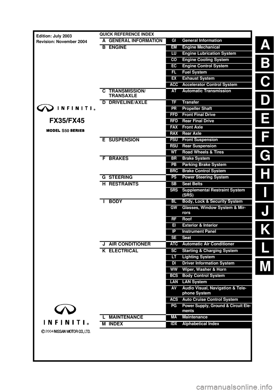
ABCDEFGHIJKMLQUICK REFERENCE INDEX AGENERAL INFORMATIONGIGeneral InformationBENGINEEMEngine MechanicalLUEngine Lubrication SystemCOEngine Cooling SystemECEngine Control SystemFLFuel SystemEXExhaust SystemACCAccelerator Control SystemCTRANSMISSION/
TRANSAXLEATAutomatic TransmissionDDRIVELINE/AXLETFTransferPRPropeller ShaftFFDFront Final DriveRFDRear Final DriveFAXFront AxleRAXRear AxleESUSPENSIONFSUFront SuspensionRSURear SuspensionWTRoad Wheels & TiresFBRAKESBRBrake SystemPBParking Brake SystemBRCBrake Control SystemGSTEERINGPSPower Steering SystemHRESTRAINTSSBSeat BeltsSRSSupplemental Restraint System
(SRS)IBODYBLBody, Lock & Security SystemGWGlasses, Window System & Mir-
rorsRFRoofEIExterior & InteriorIPInstrument PanelSESeatJAIR CONDITIONERATCAutomatic Air ConditionerKELECTRICALSCStarting & Charging SystemLTLighting SystemDIDriver Information SystemWWWiper, Washer & HornBCSBody Control SystemLANLAN SystemAVAudio Visual, Navigation & Tele-
phone SystemACSAuto Cruise Control SystemPGPower Supply, Ground & Circuit Ele-
mentsLMAINTENANCEMAMaintenanceMINDEXIDXAlphabetical IndexEdition: July 2003
Revision: November 2004
Page 592 of 4449

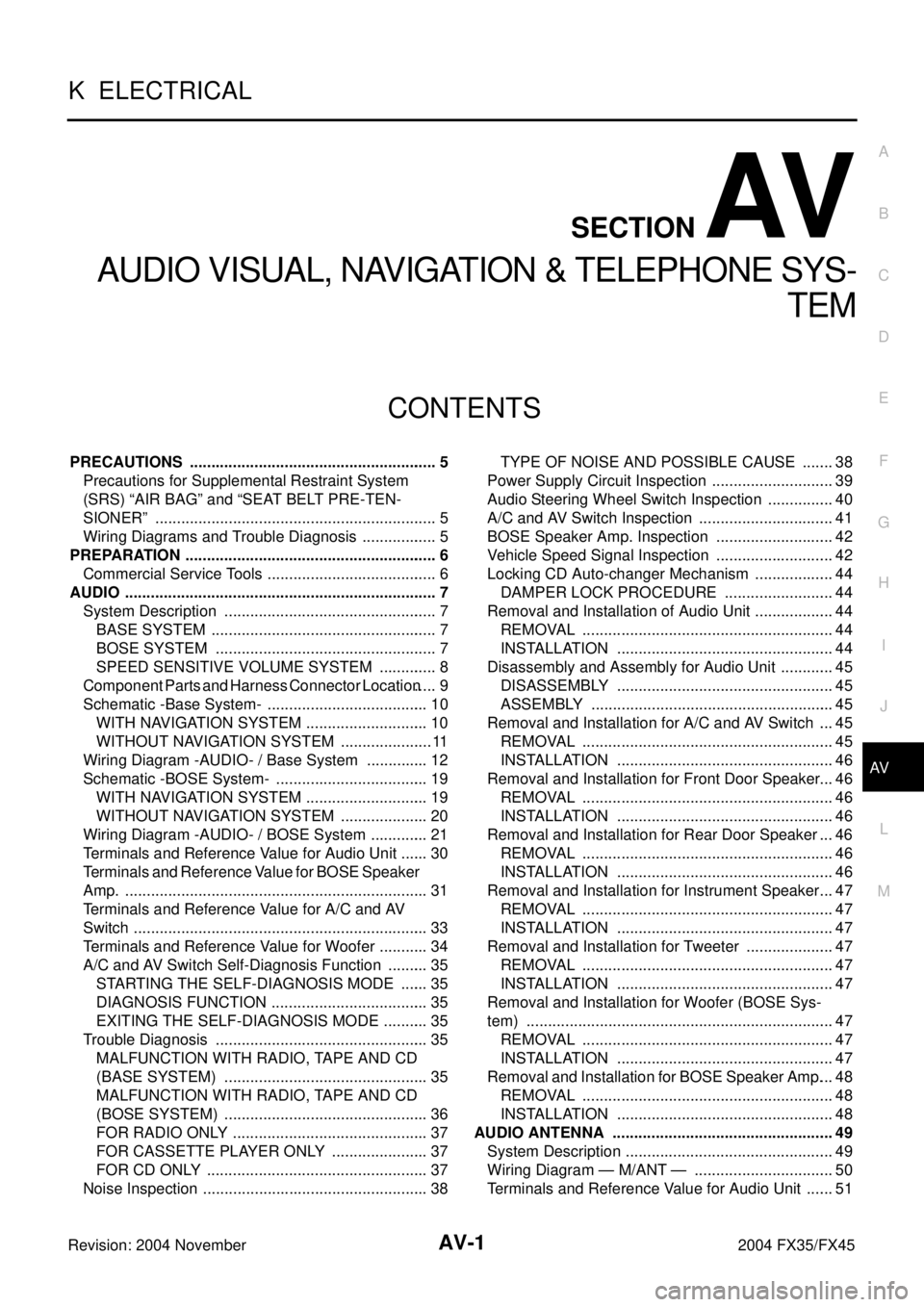
AV-1
AUDIO VISUAL, NAVIGATION & TELEPHONE SYS-
TEM
K ELECTRICAL
CONTENTS
C
D
E
F
G
H
I
J
L
M
SECTION AV
A
B
AV
Revision: 2004 November 2004 FX35/FX45
AUDIO VISUAL, NAVIGATION & TELEPHONE SYSTEM
PRECAUTIONS .......................................................... 5
Precautions for Supplemental Restraint System
(SRS) “AIR BAG” and “SEAT BELT PRE-TEN-
SIONER” .................................................................. 5
Wiring Diagrams and Trouble Diagnosis .................. 5
PREPARATION ........................................................... 6
Commercial Service Tools ........................................ 6
AUDIO ......................................................................... 7
System Description .................................................. 7
BASE SYSTEM ..................................................... 7
BOSE SYSTEM .................................................... 7
SPEED SENSITIVE VOLUME SYSTEM .............. 8
Component Parts and Harness Connector Location ..... 9
Schematic -Base System- ...................................... 10
WITH NAVIGATION SYSTEM ............................. 10
WITHOUT NAVIGATION SYSTEM ...................... 11
Wiring Diagram -AUDIO- / Base System ............... 12
Schematic -BOSE System- .................................... 19
WITH NAVIGATION SYSTEM ............................. 19
WITHOUT NAVIGATION SYSTEM ..................... 20
Wiring Diagram -AUDIO- / BOSE System .............. 21
Terminals and Reference Value for Audio Unit ....... 30
Terminals and Reference Value for BOSE Speaker
Amp. ....................................................................... 31
Terminals and Reference Value for A/C and AV
Switch ..................................................................... 33
Terminals and Reference Value for Woofer ............ 34
A/C and AV Switch Self-Diagnosis Function .......... 35
STARTING THE SELF-DIAGNOSIS MODE ....... 35
DIAGNOSIS FUNCTION ..................................... 35
EXITING THE SELF-DIAGNOSIS MODE ........... 35
Trouble Diagnosis .................................................. 35
MALFUNCTION WITH RADIO, TAPE AND CD
(BASE SYSTEM) ................................................ 35
MALFUNCTION WITH RADIO, TAPE AND CD
(BOSE SYSTEM) ................................................ 36
FOR RADIO ONLY .............................................. 37
FOR CASSETTE PLAYER ONLY ....................... 37
FOR CD ONLY .................................................... 37
Noise Inspection ..................................................... 38TYPE OF NOISE AND POSSIBLE CAUSE ........ 38
Power Supply Circuit Inspection ............................. 39
Audio Steering Wheel Switch Inspection ................ 40
A/C and AV Switch Inspection ................................ 41
BOSE Speaker Amp. Inspection ............................ 42
Vehicle Speed Signal Inspection ............................ 42
Locking CD Auto-changer Mechanism ................... 44
DAMPER LOCK PROCEDURE .......................... 44
Removal and Installation of Audio Unit ................... 44
REMOVAL ........................................................... 44
INSTALLATION ................................................... 44
Disassembly and Assembly for Audio Unit ............. 45
DISASSEMBLY ................................................... 45
ASSEMBLY ......................................................... 45
Removal and Installation for A/C and AV Switch .... 45
REMOVAL ........................................................... 45
INSTALLATION ................................................... 46
Removal and Installation for Front Door Speaker ... 46
REMOVAL ........................................................... 46
INSTALLATION ................................................... 46
Removal and Installation for Rear Door Speaker ... 46
REMOVAL ........................................................... 46
INSTALLATION ................................................... 46
Removal and Installation for Instrument Speaker ... 47
REMOVAL ........................................................... 47
INSTALLATION ................................................... 47
Removal and Installation for Tweeter ..................... 47
REMOVAL ........................................................... 47
INSTALLATION ................................................... 47
Removal and Installation for Woofer (BOSE Sys-
tem) ........................................................................ 47
REMOVAL ........................................................... 47
INSTALLATION ................................................... 47
Removal and Installation for BOSE Speaker Amp. ... 48
REMOVAL ........................................................... 48
INSTALLATION ................................................... 48
AUDIO ANTENNA .................................................... 49
System Description ................................................. 49
Wiring Diagram — M/ANT — ................................. 50
Terminals and Reference Value for Audio Unit ....... 51
Page 642 of 4449

AUDIO ANTENNA
AV-51
C
D
E
F
G
H
I
J
L
MA
B
AV
Revision: 2004 November 2004 FX35/FX45
Terminals and Reference Value for Audio UnitAKS007WW
Antenna Amp. InspectionAKS007WX
1. CHECK ANTENNA FEEDER
Check with visual observation if antenna feeder between audio unit and antenna amp. has disconnection or
malfunction on the mounting part (engagement, looseness of shield earth, etc.).
OK or NG
OK >> GO TO 2
NG >> Replace antenna feeder.
2. CHECK ANTENNA SIGNAL
1. Turn the ignition switch ACC.
2. Check voltage between audio unit harness connector M58 ter-
minal 5 (R/W) and ground.
OK or NG
OK >> INSPECTION END (System is OK)
NG >> Replace audio unit.
Terminal
(wire color)
ItemSignal
input/
outputCondition
Reference valueExample of symp-
tom
+–Ignition
switchOperation
5 (R/
W)GroundAntenna sig-
nalOutput ACC – Approx. 12VReceiving status of
radio broadcast
becomes bad.
10
(LG/R)GroundACC power
supplyInput ACC – Battery voltageSystem does not
work properly
5 – Ground : Approx. 12V
SKIA6854E
Page 3902 of 4449

HARNESS
PG-67
C
D
E
F
G
H
I
J
L
MA
B
PG
Revision: 2004 November 2004 FX35/FX45
Wiring Diagram Codes (Cell Codes) AKS007X0
Use the chart below to find out what each wiring diagram code stands for.
Refer to the wiring diagram code in the alphabetical index to find the location (page number) of each wiring
diagram.
Code Section Wiring Diagram Name
A/C ATC Air Conditioner
APPS1 EC Accelerator Pedal Position Sensor
APPS2 EC Accelerator Pedal Position Sensor
APPS3 EC Accelerator Pedal Position Sensor
ASC/BS EC Automatic Speed Control Device (ASCD) Brake Switch
ASC/SW EC Automatic Speed Control Device (ASCD) Steering Switch
ASCBOF EC Automatic Speed Control Device (ASCD) Brake Switch
ASCIND EC Automatic Speed Control Device (ASCD) Indicator
AT/IND DI A/T Indicator Lamp
AUDIO AV Audio
AUT/DP SE Automatic Drive Positioner
AUTO/L LT Automatic Light System
AWD TF AWD Control System
B/CLOS BL Back Door Closure System
BACK/L LT Back-Up Lamp
BRK/SW EC Brake Switch
CAN AT CAN Communication Line
CAN EC CAN Communication Line
CAN LAN CAN System
CHARGE SC Charging System
CHIME DI Warning Chime
CIGAR WW Cigarette Lighter
CLOCK DI Clock
COMBSW LT Combination Switch
COMM AV Audio Visual Communication Line
COMPASS DI Compass
COOL/F EC Cooling Fan Control
D/LOCK BL Power Door Lock
DEF GW Rear Window Defogger
DTRL LT Headlamp - With Daytime Light System
ECM/PW EC ECM Power Supply For Back-Up
ECTS EC Engine Coolant Temperature Sensor
ETC1 EC Electric Throttle Control Function
ETC2 EC Electric Throttle Control Motor Relay
ETC3 EC Electric Throttle Control Motor
F/FOG LT Front Fog Lamp
F/PUMP EC Fuel Pump
FTS AT A/T Fluid Temperature Sensor Circuit
FTTS EC Fuel Tank Temperature Sensor
FUELB1 EC Fuel Injection System Function (Bank 1)
FUELB2 EC Fuel Injection System Function (Bank 2)