turn signal INFINITI FX35 2008 Owners Manual
[x] Cancel search | Manufacturer: INFINITI, Model Year: 2008, Model line: FX35, Model: INFINITI FX35 2008Pages: 3924, PDF Size: 81.37 MB
Page 718 of 3924

TELEPHONEAV-171
< SERVICE INFORMATION >
C
DE
F
G H
I
J
L
M A
B
AV
N
O P
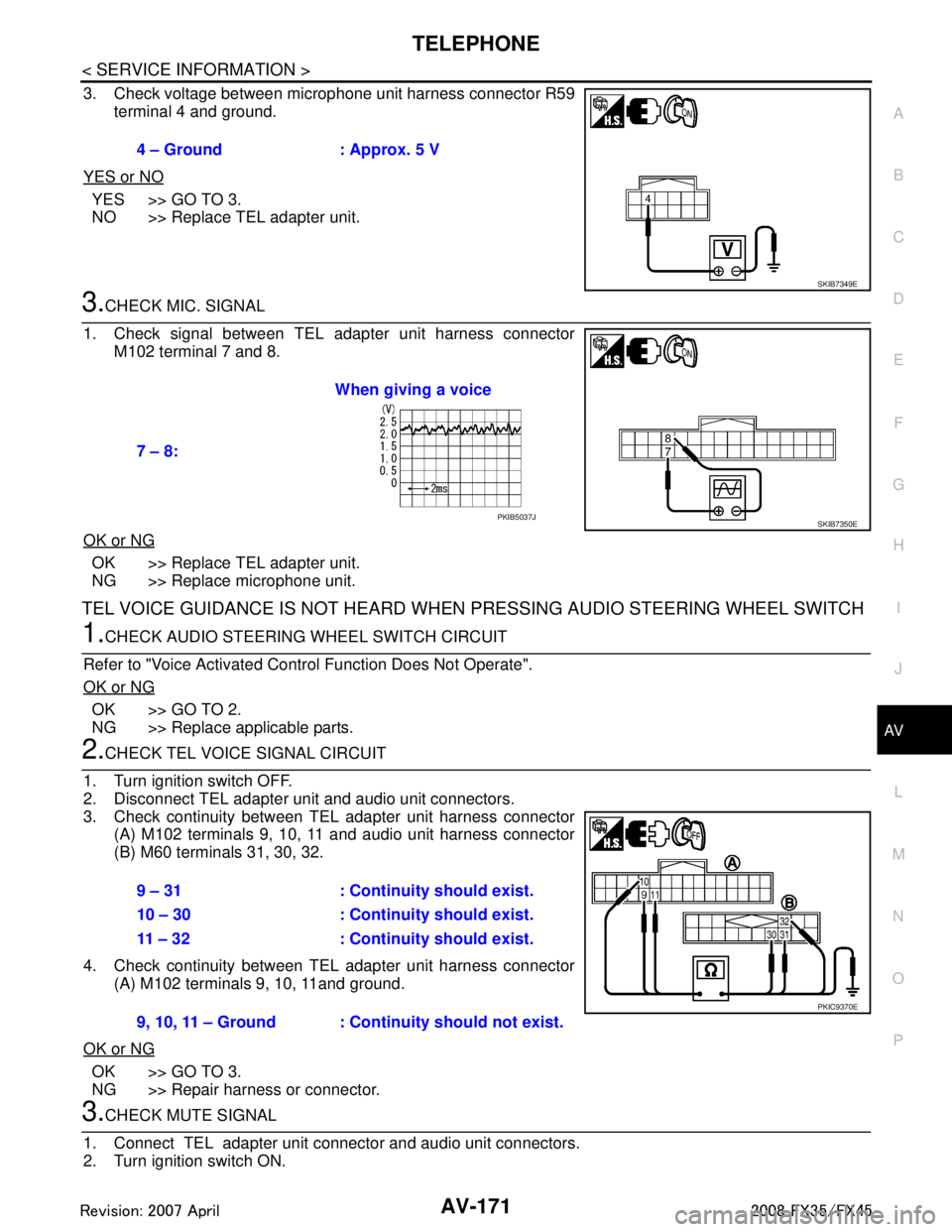
3. Check voltage between microphone unit harness connector R59 terminal 4 and ground.
YES or NO
YES >> GO TO 3.
NO >> Replace TEL adapter unit.
3.CHECK MIC. SIGNAL
1. Check signal between TEL adapter unit harness connector M102 terminal 7 and 8.
OK or NG
OK >> Replace TEL adapter unit.
NG >> Replace microphone unit.
TEL VOICE GUIDANCE IS NOT HEARD WHEN PRESSING AUDIO STEERING WHEEL SWITCH
1.CHECK AUDIO STEERING WHEEL SWITCH CIRCUIT
Refer to "Voice Activated Control Function Does Not Operate".
OK or NG
OK >> GO TO 2.
NG >> Replace applicable parts.
2.CHECK TEL VOICE SIGNAL CIRCUIT
1. Turn ignition switch OFF.
2. Disconnect TEL adapter unit and audio unit connectors.
3. Check continuity between TEL adapter unit harness connector (A) M102 terminals 9, 10, 11 and audio unit harness connector
(B) M60 terminals 31, 30, 32.
4. Check continuity between TEL adapter unit harness connector (A) M102 terminals 9, 10, 11and ground.
OK or NG
OK >> GO TO 3.
NG >> Repair harness or connector.
3.CHECK MUTE SIGNAL
1. Connect TEL adapter unit connector and audio unit connectors.
2. Turn ignition switch ON. 4 – Ground : Approx. 5 V
SKIB7349E
7 – 8:
When giving a voice
SKIB7350EPKIB5037J
9 – 31 : Continuity should exist.
10 – 30 : Continuity should exist.
11 – 32 : Continuity should exist.
9, 10, 11 – Ground : Continuity should not exist.
PKIC9370E
3AA93ABC3ACD3AC03ACA3AC03AC63AC53A913A773A893A873A873A8E3A773A983AC73AC93AC03AC3
3A893A873A873A8F3A773A9D3AAF3A8A3A8C3A863A9D3AAF3A8B3A8C
Page 724 of 3924

BCS-4
< SERVICE INFORMATION >
BCM (BODY CONTROL MODULE)
BCM (BODY CONTROL MODULE)
System DescriptionINFOID:0000000001328608
BCM (Body Control Module) controls the operation of various electrical units installed on the vehicle.
BCM FUNCTION
BCM has combination switch reading function for reading the operation of combination switches (light, wiper,
washer and turn signal) in addition to a function for cont rolling the operation of various electrical components.
Also it has an interface function allowing it to receive signals from the unified meter and A/C amp., and send
signals to ECM using CAN communication.
COMBINATION SWITCH READING FUNCTION
Description
BCM reads combination switch (lighting switch, wiper switch) status, and controls various electrical compo-
nent according to the result.
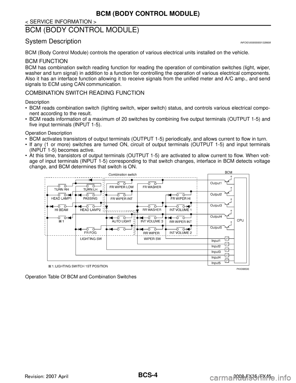
BCM reads information of a maximum of 20 switches by combining five output terminals (OUTPUT 1-5) and
five input terminals (INPUT 1-5).
Operation Description
BCM activates transistors of output terminals (OUTPUT 1-5) periodically, and allows current to flow in turn.
If any (1 or more) switches are turned ON, circui t of output terminals (OUTPUT 1-5) and input terminals
(INPUT 1-5) becomes active.
At this time, transistors of output terminals (OUTPUT 1- 5) are activated to allow current to flow. When volt-
age of input terminals (INPUT 1-5) corresponding to t hat switch changes, interface in BCM detects voltage
change, and BCM determines that switch is ON.
Operation Table Of BCM and Combination Switches
PKID0853E
3AA93ABC3ACD3AC03ACA3AC03AC63AC53A913A773A893A873A873A8E3A773A983AC73AC93AC03AC3
3A893A873A873A8F3A773A9D3AAF3A8A3A8C3A863A9D3AAF3A8B3A8C
Page 725 of 3924

BCM (BODY CONTROL MODULE)BCS-5
< SERVICE INFORMATION >
C
DE
F
G H
I
J
L
M A
B
BCS
N
O P
BCM reads operation status of combination swit ch using combinations shown in table below.
NOTE:
Headlamp system has a dual switch.
Sample Operation: (When Lighting Switch 1ST Position Turned ON)
When lighting switch 1ST position is turned ON, contact in combination switch turns ON. At this time if OUT-
PUT 4 transistor is activated, BCM detects that voltage changes in INPUT 5.
When OUTPUT 4 transistor is ON, BCM detects that voltage changes in INPUT 5, and judges that lighting
switch 1ST position is ON. Then BCM sends tail lamp and clearance lamp request signal to IPDM E/R using
CAN communication.
When OUTPUT 4 transistor is activated again, BCM detects that voltage changes in INPUT 5, and recog-
nizes that lighting switch 1S T position is continuously ON.
NOTE:
Each OUTPUT terminal transistor is activated at 10 ms intervals. Therefore after switch is turned ON, electri-
cal loads are activated with time delay. But this time delay is so short that it cannot be detected by human
senses.
Operation Mode
Combination switch reading function has operation modes shown below.
1. Normal status When BCM is not in sleep status, OUTPUT terminals (1-5) send out ON signal every 10 ms.
2. Sleep status
SKIA4959E
PKID0854E
3AA93ABC3ACD3AC03ACA3AC03AC63AC53A913A773A893A873A873A8E3A773A983AC73AC93AC03AC3
3A893A873A873A8F3A773A9D3AAF3A8A3A8C3A863A9D3AAF3A8B3A8C
Page 726 of 3924

BCS-6
< SERVICE INFORMATION >
BCM (BODY CONTROL MODULE)
When BCM is in sleep status, transistors of OUTPUT 1 and 5 stop the output, and BCM enters low power
mode. Mean while OUTPUT 2, 3, and 4 send out ON signal every 60 ms, and accept input from lighting
switch system.
CAN COMMUNICATION CONTROL
CAN communication allows a high rate of information transmission through the two communication lines (CAN
L line, CAN H line) connecting the various control units in the system. Each control unit transmits/receives
data but selectively reads required data only. For details of signals that are transmitted/received by BCM via
CAN communication, refer to LAN-43, "
CAN System Specification Chart".
BCM STATUS CONTROL
BCM changes its status depending on the operation stat us in order to save power consumption.
1. CAN communication status With ignition switch ON, CAN communicates with other control units normally.
Control by BCM is being operated properly.
When ignition switch is OFF, switching to sleep mode is possible.
Even when ignition switch is OFF, if CAN communication with IPDM E/R and combination meter isactive, CAN communication status is active.
2. Sleep transient status This status shuts down CAN communication when ignition switch is turned OFF.
It transmits sleep request signal to IPDM E/R and combination meter.
2 seconds after CAN communication of all control units stops, sleep transient status is switched to CAN
communication inactive status.
3. CAN communication inactive status With ignition switch OFF, CAN communication is not active.
With ignition switch OFF, control performed only by BCM is active.
3 seconds after CAN communication of all control units stops, CAN communication inactive status is
switched to sleep status.
4. Sleep status BCM is activated with low power mode.
CAN communication is not active.
When CAN communication operation is detected, it switches to CAN communication status.
When a state of the following switches changes , it switches to CAN communication state.
- Key switch
- Hazard switch
PKIC4919E
3AA93ABC3ACD3AC03ACA3AC03AC63AC53A913A773A893A873A873A8E3A773A983AC73AC93AC03AC3
3A893A873A873A8F3A773A9D3AAF3A8A3A8C3A863A9D3AAF3A8B3A8C
Page 727 of 3924

BCM (BODY CONTROL MODULE)BCS-7
< SERVICE INFORMATION >
C
DE
F
G H
I
J
L
M A
B
BCS
N
O P
- Door lock/unlock switch
- Front door switch (driver side, passenger side)
- Rear door switch (LH, RH)
- Back door opener switch
- Combination switch (passing, lighting switch 1ST position, front fog lamp)
- Key fob (lock/unlock signal)
- Key cylinder switch
When control performed only by BCM is required by switch, it shifts to CAN communication inactive mode.
Operation mode of combination switch reading function is changed.
SYSTEMS CONTROLLED BY BCM DIRECTLY
NOTE:
Power supply only. No system control.
SYSTEMS CONTROLLED BY BCM AND IPDM E/R
SYSTEMS CONTROLLED BY BCM AND COMBINATION METER
SYSTEMS CONTROLLED BY BCM AND INTELLIGENT KEY UNIT
SYSTEMS CONTROLLED BY BCM, CO MBINATION METER AND IPDM E/R
System Reference
Power door lock system BL-21
Remote keyless entry systemBL-50
Power window system NOTEGW-15
Sunroof NOTERF-10
Room lamp timerLT- 1 3 8
Rear wiper and washer systemWW-30
System Reference
Panic alarm
BL-50
BL-76
Theft warning system BL-163
IVIS (NATS)BL-185
HeadlampLT- 5
Daytime light systemLT- 3 2
Auto light systemLT- 4 7
Front fog lampLT- 6 6
Parking, license plate, side marker and tail lamps
Exterior lamp battery saver control LT- 11 8
Front wiper and washer system
WW-4
Rear window defoggerGW-60
System Reference
Warning chime DI-51
Turn signal and hazard warning lampsLT- 7 8
Tire pressure monitoring systemWT-10
System Reference
Intelligent Key system BL-76
3AA93ABC3ACD3AC03ACA3AC03AC63AC53A913A773A893A873A873A8E3A773A983AC73AC93AC03AC3
3A893A873A873A8F3A773A9D3AAF3A8A3A8C3A863A9D3AAF3A8B3A8C
Page 728 of 3924

BCS-8
< SERVICE INFORMATION >
BCM (BODY CONTROL MODULE)
MAJOR COMPONENTS AND CONTROL SYSTEM
System Reference
Oil pressure warning lamp DI-34
System Input Output
Remote control entry system Key fob All-door locking actuator
Fuel lid Lock actuator
Turn signal lamp (LH, RH)
Combination meter
Intelligent Key system Intelligent Key unit All-door locking actuator
Fuel lid Lock actuator
Turn signal lamp (LH, RH)
Combination meter
Power door lock system Power window main switch
(door lock and unlock switch)
Power window sub switch (passenger side) (door lock and unlock switch) All-door locking actuator
Power supply (IGN) to power window, sunroof Ignition power supply Power window and sunroof system
Power supply (BAT) to power window, sunroof
and power seat Battery power supplyPower window, sunroof system and
power seat
Panic alarm Key switch
Key fobIPDM E/R
Theft warning system All-door switch
Hood switch
Key fob
Power window main switch (door lock and
unlock switch)
Power window sub switch (passenger side) (door lock and unlock switch) IPDM E/R
Security indicator lamp
Auto light system Optical sensor
Combination switch
Ignition switchIPDM E/R
Exterior lamp battery saver control Ignition switch
Combination switchIPDM E/R
Headlamp Combination switch IPDM E/R
Daytime light system Combination meter
ECM
Combination switch
Ignition switchIPDM E/R
Parking, license plate, side marker and tail
lamps Combination switch IPDM E/R
Front fog lamp Combination switch IPDM E/R
Turn signal lamp Combination switch
Ignition switch Turn signal lamp
Combination meter
Hazard lamp Hazard switch Turn signal lamp
Combination meter
Room lamp timer Key switch
Key fob
Power window main switch (door lock and
unlock switch)
Front door switch driver side
All-door switch Interior room lamp
Key warning chime Key switch
Front door switch driver sideCombination meter
(warning buzzer)
3AA93ABC3ACD3AC03ACA3AC03AC63AC53A913A773A893A873A873A8E3A773A983AC73AC93AC03AC3
3A893A873A873A8F3A773A9D3AAF3A8A3A8C3A863A9D3AAF3A8B3A8C
Page 732 of 3924

BCS-12
< SERVICE INFORMATION >
BCM (BODY CONTROL MODULE)
ITEMS OF EACH PART
BCM can perform the following functions for each system.
NOTE:
CONSULT-III displays systems equipped in the vehicle.
×:Applicable
NOTE:
*1: Vehicle with remote keyless entry system display this item.
*2: Vehicle with Intelligent Key system display this item.
*3: This item is displayed, but does not function.
WORK SUPPORT
Display Item List
BCM Diagnostic test item Check item, diagnostic test mode Content
Inspection by part WORK SUPPORT Changes setting of each function.
SELF-DIAG RESULTS BCM performs self-diagnosis of CAN communication.
DATA MONITOR Displays the input data of BCM in real time.
CAN DIAG SUPPORT MNTR
The transmit/receive diagnosis result of CAN communication can be
read.
ACTIVE TEST Gives a drive signal to a load to check the operation.
ECU PART NUMBER ECM part number can be read.
CONFIGURATION (Not be used)
System and item CONSULT-III display Diagnostic test mode (Inspection by part)
WORK SUPPORT DATA MONITOR ACTIVE TEST
BCM BCM ×
Power door lock system DOOR LOCK ×××
Rear window defogger REAR DEFOGGER ××
Warning chime BUZZER ××
Room lamp timer INT LAMP ×××
Remote keyless entry system*
1MULTI REMOTE ENT ×××
Headlamp HEAD LAMP ×××
Wiper WIPER ×××
Turn signal lamp
Hazard lamp FLASHER
××
Blower fan switch signal
A/C switch signal AIR CONDITONER
×
Intelligent Key system*
2INTELLIGENT KEY ×
Combination switch COMB SW ×
NVIS IMMU ××
Room lamp battery saver BATTERY SAVER ×× ×
Trunk lid TRUNK*
3××
Vehicle security system THEFT ALM ×××
Retained power control RETAINED PWR ×××
Oil pressure swit ch SIGNAL BUFFER ××
Low tire pressure warning system AIR PRESSURE MONITOR ×××
Panic system PANIC ALARM ×
3AA93ABC3ACD3AC03ACA3AC03AC63AC53A913A773A893A873A873A8E3A773A983AC73AC93AC03AC3
3A893A873A873A8F3A773A9D3AAF3A8A3A8C3A863A9D3AAF3A8B3A8C
Page 733 of 3924

BCM (BODY CONTROL MODULE)BCS-13
< SERVICE INFORMATION >
C
DE
F
G H
I
J
L
M A
B
BCS
N
O P
SELF-DIAG RESULTS
U1000 CAN Communication CircuitINFOID:0000000001606767
1.PERFORM SELF DIAGNOSTIC
1. Turn ignition switch ON and wait for 2 seconds or more.
2. Check “Self Diagnostic Result” of BCM.
Is
“CAN COMM CIRCUIT” displayed?
YES >> Refer to LAN-14, "Trouble Diagnosis Flow Chart".
NO >> Refer to GI-25, "
How to Perform Efficient Diagnosis for an Electrical Incident".
Removal and Installation of BCMINFOID:0000000001328613
REMOVAL
1. Remove the dash side finisher (LH). Refer to EI-38.
2. Disconnect BCM connector.
3. Remove bracket mounting screws (3) to remove BCM and fuse block with bracket.
Item Description
RESET SETTING VALUE Return a value set with WORK SUPPORT of each system to a default value in factory shipment.
DTC DTC Detection Condition Possible cause
U1000: CAN COMM CIRCUIT When BCM cannot communicate CAN com-
munication signal continuously for 2 sec-
onds or more. Any item (or items) of the following listed below is
malfunctioning in CAN communication system.
Transmission
Receiving (ECM)
Receiving (IPDM E/R)
Receiving (METER/M&A)
Receiving (I-KEY)
SKIA4964E
3AA93ABC3ACD3AC03ACA3AC03AC63AC53A913A773A893A873A873A8E3A773A983AC73AC93AC03AC3
3A893A873A873A8F3A773A9D3AAF3A8A3A8C3A863A9D3AAF3A8B3A8C
Page 772 of 3924

BL-38
< SERVICE INFORMATION >
POWER DOOR LOCK SYSTEM
NOTE:
Refer to BL-21, "
Component Parts and Harness Connector Location".
OK or NG
OK >> GO TO 2.
NG >> If fuse is blown, be sure to eliminate caus e of malfunction before installing new fuse, refer to PG-
3.
2.CHECK POWER SUPPLY CIRCUIT
1. Turn ignition switch OFF.
2. Disconnect BCM connectors.
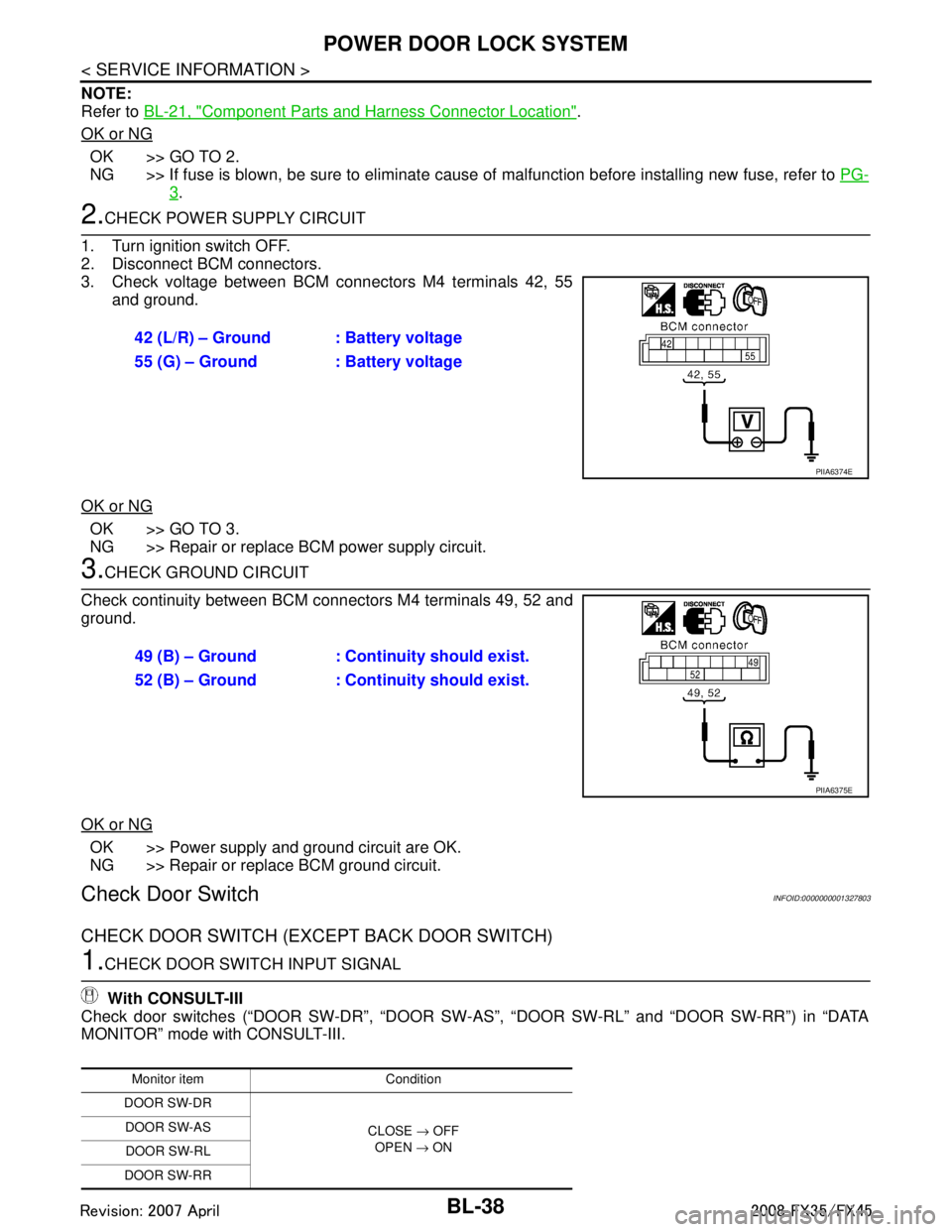
3. Check voltage between BCM connectors M4 terminals 42, 55 and ground.
OK or NG
OK >> GO TO 3.
NG >> Repair or replace BCM power supply circuit.
3.CHECK GROUND CIRCUIT
Check continuity between BCM connectors M4 terminals 49, 52 and
ground.
OK or NG
OK >> Power supply and ground circuit are OK.
NG >> Repair or replace BCM ground circuit.
Check Door SwitchINFOID:0000000001327803
CHECK DOOR SWITCH (EXCEPT BACK DOOR SWITCH)
1.CHECK DOOR SWITCH INPUT SIGNAL
With CONSULT-III
Check door switches (“DOOR SW-DR”, “DOOR SW- AS”, “DOOR SW-RL” and “DOOR SW-RR”) in “DATA
MONITOR” mode with CONSULT-III. 42 (L/R) – Ground : Battery voltage
55 (G) – Ground : Battery voltage
PIIA6374E
49 (B) – Ground : Continuity should exist.
52 (B) – Ground : Continuity should exist.
PIIA6375E
Monitor item Condition
DOOR SW-DR
CLOSE → OFF
OPEN → ON
DOOR SW-AS
DOOR SW-RL
DOOR SW-RR
3AA93ABC3ACD3AC03ACA3AC03AC63AC53A913A773A893A873A873A8E3A773A983AC73AC93AC03AC3
3A893A873A873A8F3A773A9D3AAF3A8A3A8C3A863A9D3AAF3A8B3A8C
Page 774 of 3924

BL-40
< SERVICE INFORMATION >
POWER DOOR LOCK SYSTEM
NG >> Repair or replace harness.
3.CHECK DOOR SWITCH
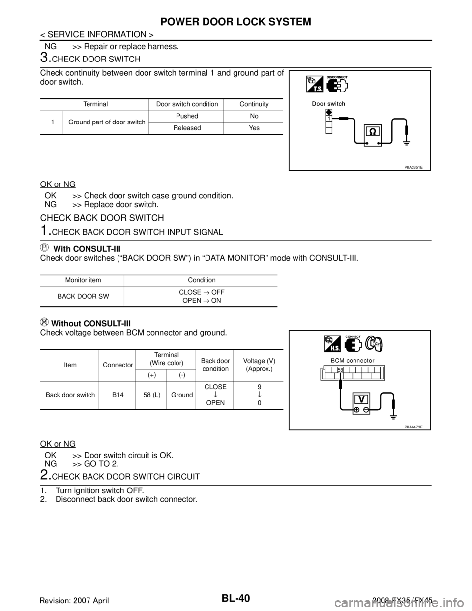
Check continuity between door switch terminal 1 and ground part of
door switch.
OK or NG
OK >> Check door switch case ground condition.
NG >> Replace door switch.
CHECK BACK DOOR SWITCH
1.CHECK BACK DOOR SWITCH INPUT SIGNAL
With CONSULT-III
Check door switches (“BACK DOOR SW”) in “DATA MONITOR” mode with CONSULT-III.
Without CONSULT-III
Check voltage between BCM connector and ground.
OK or NG
OK >> Door switch circuit is OK.
NG >> GO TO 2.
2.CHECK BACK DOOR SWITCH CIRCUIT
1. Turn ignition switch OFF.
2. Disconnect back door switch connector.
Terminal Door switch condition Continuity
1 Ground part of door switch Pushed No
Released Yes
PIIA3351E
Monitor item Condition
BACK DOOR SW CLOSE
→ OFF
OPEN → ON
Item Connector Te r m i n a l
(Wire color) Back door
condition Voltage (V)
(Approx.)
(+) (-)
Back door switch B14 58 (L) Ground CLOSE
↓
OPEN 9
↓ 0
PIIA6473E
3AA93ABC3ACD3AC03ACA3AC03AC63AC53A913A773A893A873A873A8E3A773A983AC73AC93AC03AC3
3A893A873A873A8F3A773A9D3AAF3A8A3A8C3A863A9D3AAF3A8B3A8C