torque INFINITI FX35 2008 Service Manual
[x] Cancel search | Manufacturer: INFINITI, Model Year: 2008, Model line: FX35, Model: INFINITI FX35 2008Pages: 3924, PDF Size: 81.37 MB
Page 3029 of 3924
![INFINITI FX35 2008 Service Manual
TROUBLE DIAGNOSISLAN-9
< SERVICE INFORMATION > [CAN FUNDAMENTAL]
C
D
E
F
G H
I
J
L
M A
B
LAN
N
O P
Example: Main Line Between Data Link
Connector and ABS Actuator and Electr ic Unit (Control Unit) O INFINITI FX35 2008 Service Manual
TROUBLE DIAGNOSISLAN-9
< SERVICE INFORMATION > [CAN FUNDAMENTAL]
C
D
E
F
G H
I
J
L
M A
B
LAN
N
O P
Example: Main Line Between Data Link
Connector and ABS Actuator and Electr ic Unit (Control Unit) O](/img/42/57017/w960_57017-3028.png)
TROUBLE DIAGNOSISLAN-9
< SERVICE INFORMATION > [CAN FUNDAMENTAL]
C
D
E
F
G H
I
J
L
M A
B
LAN
N
O P
Example: Main Line Between Data Link
Connector and ABS Actuator and Electr ic Unit (Control Unit) Open Circuit
Example: CAN-H, CAN-L Harness Short Circuit
SKIB8740E
Unit name Symptom
ECM Engine torque limiting is affected, and shift harshness increases.
BCM Reverse warning chime does not sound.
The front wiper moves under continuous operation mode even though the front wip-
er switch being in the intermittent position.
EPS control unit The steering effort increases.
Combination meter The shift position indicator and OD OFF indicator turn OFF.
The speedometer is inoperative.
The odo/trip meter stops.
ABS actuator and electric unit (control unit) Normal operation.
TCM No impact on operation.
IPDM E/R When the ignition switch is ON,
The headlamps (Lo) turn ON.
The cooling fan continues to rotate.
SKIB8741E
3AA93ABC3ACD3AC03ACA3AC03AC63AC53A913A773A893A873A873A8E3A773A983AC73AC93AC03AC3
3A893A873A873A8F3A773A9D3AAF3A8A3A8C3A863A9D3AAF3A8B3A8C
Page 3030 of 3924
![INFINITI FX35 2008 Service Manual
LAN-10
< SERVICE INFORMATION >[CAN FUNDAMENTAL]
TROUBLE DIAGNOSIS
Self-Diagnosis
INFOID:0000000001451950
CAN Diagnostic Support MonitorINFOID:0000000001451951
CONSULT-III and CAN diagnostic support m INFINITI FX35 2008 Service Manual
LAN-10
< SERVICE INFORMATION >[CAN FUNDAMENTAL]
TROUBLE DIAGNOSIS
Self-Diagnosis
INFOID:0000000001451950
CAN Diagnostic Support MonitorINFOID:0000000001451951
CONSULT-III and CAN diagnostic support m](/img/42/57017/w960_57017-3029.png)
LAN-10
< SERVICE INFORMATION >[CAN FUNDAMENTAL]
TROUBLE DIAGNOSIS
Self-Diagnosis
INFOID:0000000001451950
CAN Diagnostic Support MonitorINFOID:0000000001451951
CONSULT-III and CAN diagnostic support monitor (on-boar d diagnosis function) are used for detecting root
cause.
MONITOR ITEM (CONSULT-III)
Unit name Symptom
ECM Engine torque limiting is affected, and shift harshness increases.
Engine speed drops.
BCM Reverse warning chime does not sound.
The front wiper moves under continuous operation mode even though the front
wiper switch being in the intermittent position.
The room lamp does not turn ON.
The engine does not start (if an error or malfunction occurs while turning the igni- tion switch OFF.)
The steering lock does not release (if an error or malfunction occurs while turning the ignition switch OFF.)
EPS control unit The steeri ng effort increases.
Combination meter The tachometer and the speedometer do not move.
Warning lamps turn ON.
Indicator lamps do not turn ON.
ABS actuator and electric unit (control unit) Normal operation.
TCM No impact on operation.
IPDM E/R When the ignition switch is ON,
The headlamps (Lo) turn ON.
The cooling fan continues to rotate.
DTC
Self-diagnosis item
(CONSULT-III indication) DTC detection condition Inspection/Action
U1000 CAN COMM CIRCUIT When ECM is not transmitting or receiving CAN
communication signal of OBD (emission-related
diagnosis) for 2 seconds or more.
Refer to LAN-13
.
When a control unit (except for ECM) is not
transmitting or receiving CAN communication
signal for 2 seconds or more.
U1001 CAN COMM CIRCUIT When ECM is not transmitting or receiving CAN
communication signal other than OBD (emis-
sion-related diagnosis) for 2 seconds or more.
U1002 SYSTEM COMM When a control unit is not transmitting or receiv-
ing CAN communication signal for 2 seconds or
less. Start the inspection. Re-
fer to the applicable sec-
tion of the indicated
control unit.
U1010 CONTROL UNIT [CAN] When an error is detected during the initial diag-
nosis for CAN controller of each control unit. Replace the control unit
indicating “U1010”.
3AA93ABC3ACD3AC03ACA3AC03AC63AC53A913A773A893A873A873A8E3A773A983AC73AC93AC03AC3
3A893A873A873A8F3A773A9D3AAF3A8A3A8C3A863A9D3AAF3A8B3A8C
Page 3346 of 3924

CHASSIS AND BODY MAINTENANCEMA-29
< SERVICE INFORMATION >
C
DE
F
G H
I
J
K
M A
B
MA
N
O P
2. Check fluid level. CAUTION:
Carefully fill the fluid. (Fil l up for Approx. 3 minutes.)
Checking Propeller ShaftINFOID:0000000001328923
Check propeller shaft for damage, looseness or grease leakage.
Checking Differential Gear OilINFOID:0000000001328924
Check for oil leakage.
Changing Differential Gear OilINFOID:0000000001328925
1. Drain oil from drain plug and refill with new gear oil.Fluid grade:
Genuine NISSAN Matic D ATF (Continental U.S. and
Alaska) or Canada NISSAN Automatic Transmis-
sion Fluid or equivalent (if available)
Refer to MA-9
.
Fluid capacity:
: Approx. 1.25 (2-5/8 US pt, 2-1/4 lmp pt)
Drain plug:
: 29.4 N·m (3.0 kg-m, 22 ft-lb)
Filler plug:
: 35 N·m (3.6 kg-m, 26 ft-lb)
SDIA2087E
Tightening torque: Refer to PR-7
SMA118A
SMA012C
3AA93ABC3ACD3AC03ACA3AC03AC63AC53A913A773A893A873A873A8E3A773A983AC73AC93AC03AC3
3A893A873A873A8F3A773A9D3AAF3A8A3A8C3A863A9D3AAF3A8B3A8C
Page 3348 of 3924

CHASSIS AND BODY MAINTENANCEMA-31
< SERVICE INFORMATION >
C
DE
F
G H
I
J
K
M A
B
MA
N
O P
a. Install balance weight in the position shown in the figure at right.
b. When installing balance weight to road wheels, set it into the grooved area on the inner wall of the road wheel as shown in the
figure so that the balance weight center is aligned with the tire
balance machine indication position (angle).
CAUTION:
Always use genuine NISSAN adhesion balance weights.
Balance weights are unreusable; always replace with newones.
Do not install more than three sheets of balance weight.
c. If calculated balance weight value exceeds 50 g (1.76 oz), install two balance weight sheets in line with each other (as shown in
the figure).
CAUTION:
Do not install one balance weig ht sheet on top of another.
3. Start tire balance machine again.
4. Install drive-in balance weight on inner side of road wheel in the tire balance machine indication position (angle).
CAUTION:
Do not install more than two balance weights.
5. Start tire balance machine. Make sure that inner and outer resid- ual unbalance values are 5.0 g (0.18 oz) each or below.
If either residual unbalance value exceeds 5.0 g (0.18 oz), repeat installation procedures.
Tire RotationINFOID:0000000001328927
After rotation the tires, adjust the tire pressure.
Retighten the wheel nuts when the vehicle has been driven for
1,000 km (600 miles) (also in cases of a flat tire, etc.).
CAUTION:
Do not include the T-type spare tire when rotating the tires.
When installing wheels, tighte n them diagonally by dividing
the work two to three times in order to prevent the wheels
from developing any distortion.
Be careful not to tighten wh eel nut at torque exceeding the
criteria for preventing strain of disc rotor.
Use NISSAN genuine wheel nu ts for aluminum wheels.
SEIA0271E
Maximum allowable un-
balanceDynamic (At rim flange) Less than 5.0 g (0.18 oz) (one side)
Static (At rim flange) Less than 20 g (0.71 oz)
SMA056D
Tightening torque of wheel nut
: 108 N·m (11 kg, 83 ft-lb)SMA829C
3AA93ABC3ACD3AC03ACA3AC03AC63AC53A913A773A893A873A873A8E3A773A983AC73AC93AC03AC3
3A893A873A873A8F3A773A9D3AAF3A8A3A8C3A863A9D3AAF3A8B3A8C
Page 3360 of 3924

PARKING BRAKE CONTROLPB-5
< SERVICE INFORMATION >
C
DE
G H
I
J
K L
M A
B
PB
N
O P
12. Remove right and left rear cables installation nuts, bolts, and remove right and left rear cable assembly from the vehicle.
INSTALLATION
1. Install in the reverse order of removal. Tighten the mounting bolts and nuts to the specified torque. Referto PB-4, "
Component".
CAUTION:
Do not reuse adjusting nut after removing it.
2. Adjust parking brake. Refer to PB-3, "
On-Vehicle Inspection".
3AA93ABC3ACD3AC03ACA3AC03AC63AC53A913A773A893A873A873A8E3A773A983AC73AC93AC03AC3
3A893A873A873A8F3A773A9D3AAF3A8A3A8C3A863A9D3AAF3A8B3A8C
Page 3445 of 3924

NOISE, VIBRATION AND HARSHNESS (NVH) TROUBLESHOOTINGPR-3
< SERVICE INFORMATION >
CEF
G H
I
J
K L
M A
B
PR
N
O P
NOISE, VIBRATION AND HARSHN ESS (NVH) TROUBLESHOOTING
NVH Troubleshooting ChartINFOID:0000000001327465
Use the chart below to help you find t he cause of the symptom. If necessary, repair or replace these parts.
×: Applicable
Reference page
Front
PR-4—
—
—
—
PR-4PR-4
NVH in FFD an d RFD section
NVH in FAX, RAX, FS U, and RSU section
NVH in WT section
NVH in WT section
NVH in RAX section
NVH in BR section
NVH in PS section
RearPR-7PR-9—
PR-8—
PR-7PR-9
Possible cause and SUSPECTED PARTS
Uneven rotating torque
Center bearing improper installation
Excessive center bearing axial end play
Center bearing mounting (insulator) cracks, damage or deterioration
Excessive joint angle
Rotation imbalance
Excessive runout
DIFFERENTIAL
AXLE AND SUSPENSION
TIRE
ROAD WHEEL
DRIVE SHAFT
BRAKE
STEERING
Symptom Noise
××××××××××××××
Shake × × ××××××
Vibration ××××××× ×× × ×
3AA93ABC3ACD3AC03ACA3AC03AC63AC53A913A773A893A873A873A8E3A773A983AC73AC93AC03AC3
3A893A873A873A8F3A773A9D3AAF3A8A3A8C3A863A9D3AAF3A8B3A8C
Page 3448 of 3924

PR-6
< SERVICE INFORMATION >
FRONT PROPELLER SHAFT
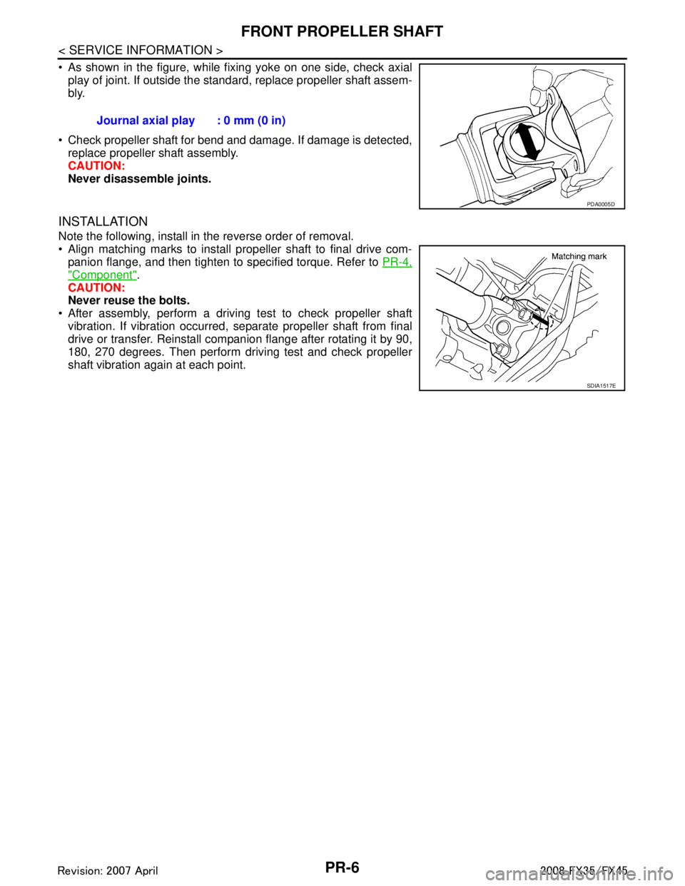
As shown in the figure, while fixing yoke on one side, check axialplay of joint. If outside the standard, replace propeller shaft assem-
bly.
Check propeller shaft for bend and damage. If damage is detected, replace propeller shaft assembly.
CAUTION:
Never disassemble joints.
INSTALLATION
Note the following, install in the reverse order of removal.
Align matching marks to install propeller shaft to final drive com-panion flange, and then tighten to specified torque. Refer to PR-4,
"Component".
CAUTION:
Never reuse the bolts.
After assembly, perform a driving test to check propeller shaft vibration. If vibration occurred, separate propeller shaft from final
drive or transfer. Reinstall companion flange after rotating it by 90,
180, 270 degrees. Then perform driving test and check propeller
shaft vibration again at each point. Journal axial play : 0 mm (0 in)
PDA0005D
SDIA1517E
3AA93ABC3ACD3AC03ACA3AC03AC63AC53A913A773A893A873A873A8E3A773A983AC73AC93AC03AC3
3A893A873A873A8F3A773A9D3AAF3A8A3A8C3A863A9D3AAF3A8B3A8C
Page 3452 of 3924

PR-10
< SERVICE INFORMATION >
REAR PROPELLER SHAFT
Inspect propeller shaft runout at measuring points. If runoutexceeds specifications, replace propeller shaft assembly. For mea-
suring point, refer to PR-4, "
On-Vehicle Inspection".
As shown in the figure, while fixing yoke on one side, check axial play of joint. If outside the standard, replace relevant propeller
shaft.
Check propeller shaft for bend and damage. If damage is detected, replace relevant propeller shaft.
CAUTION:
Never disassemble joints.
Check center bearing for noise and damage. If noise or damage is
detected, replace center bearing. Refer to PR-11, "
Disassembly
and Assembly of Center Bearing".
INSTALLATION
Note the following, and install in the reverse order of removal.
CAUTION:
Avoid damaging the rebro joint boot, protect it with a shop towel or equivalent.
Align matching marks to install propeller shaft to final drive and transfer (AWD models only) companion
flanges, and then tighten to specified torque. Refer to PR-8, "
Component".
Install center bearing mounting bracket (Upper) with its arrow mark
facing forward.
Adjust position of mounting bracket sliding back and forth to pre- vent play in thrust direction of center bearing insulator. Install
bracket to vehicle.
After assembly, perform a driving test to check propeller shaft vibration. If vibration occurred, separate propeller shaft from final
drive. Reinstall companion flange after rotating it by 60, 120, 180,
240, 300 degrees. Then perform driving test and check propeller
shaft vibration again at each point.
If propeller shaft or final drive has been replaced, connect them as follows: Propeller shaft runout limit : 0.8 mm (0.031 in)
SDIA2071E
Journal axial play : 0 mm (0 in)
SPD874
PDIA0017E
3AA93ABC3ACD3AC03ACA3AC03AC63AC53A913A773A893A873A873A8E3A773A983AC73AC93AC03AC3
3A893A873A873A8F3A773A9D3AAF3A8A3A8C3A863A9D3AAF3A8B3A8C
Page 3453 of 3924

REAR PROPELLER SHAFTPR-11
< SERVICE INFORMATION >
CEF
G H
I
J
K L
M A
B
PR
N
O P
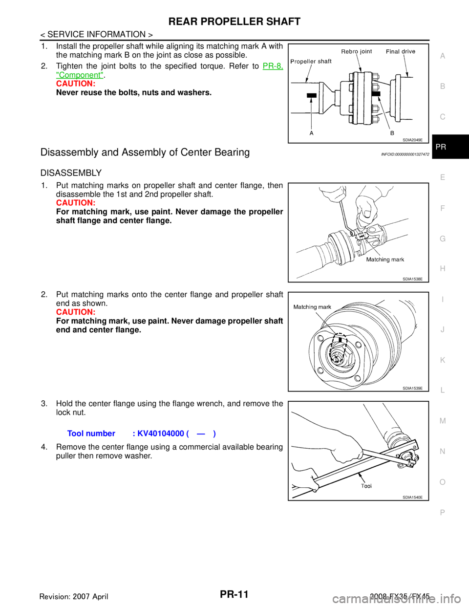
1. Install the propeller shaft while aligning its matching mark A with the matching mark B on the joint as close as possible.
2. Tighten the joint bolts to the specified torque. Refer to PR-8,
"Component".
CAUTION:
Never reuse the bolts, nuts and washers.
Disassembly and Assembly of Center BearingINFOID:0000000001327472
DISASSEMBLY
1. Put matching marks on propeller shaft and center flange, then
disassemble the 1st and 2nd propeller shaft.
CAUTION:
For matching mark, use paint. Never damage the propeller
shaft flange and center flange.
2. Put matching marks onto the center flange and propeller shaft end as shown.
CAUTION:
For matching mark, use paint. Never damage propeller shaft
end and center flange.
3. Hold the center flange using the flange wrench, and remove the lock nut.
4. Remove the center flange using a commercial available bearing puller then remove washer.
SDIA2049E
SDIA1538E
SDIA1539E
Tool number : KV40104000 ( — )
SDIA1540E
3AA93ABC3ACD3AC03ACA3AC03AC63AC53A913A773A893A873A873A8E3A773A983AC73AC93AC03AC3
3A893A873A873A8F3A773A9D3AAF3A8A3A8C3A863A9D3AAF3A8B3A8C
Page 3454 of 3924

PR-12
< SERVICE INFORMATION >
REAR PROPELLER SHAFT
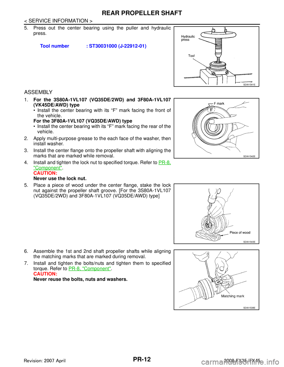
5. Press out the center bearing using the puller and hydraulic
press.
ASSEMBLY
1. For the 3S80A-1VL107 (VQ35DE/2WD) and 3F80A-1VL107
(VK45DE/AWD) type
Install the center bearing with its “F” mark facing the front of
the vehicle.
For the 3F80A-1VL107 (VQ35DE/AWD) type
Install the center bearing with its “F” mark facing the rear of the vehicle.
2. Apply multi-purpose grease to the each face of the washer, then install washer.
3. Install the center flange onto the propeller shaft with aligning the marks that are marked while removal.
4. Install and tighten the lock nut to specified torque. Refer to PR-8,
"Component".
CAUTION:
Never use the lock nut.
5. Place a piece of wood under the center flange, stake the lock nut against the propeller shaft groove. [For the 3S80A-1VL107
(VQ35DE/2WD) and 3F80A-1 VL107 (VQ35DE/AWD) type]
6. Assemble the 1st and 2nd shaft propeller shafts while aligning the matching marks that are marked during removal.
7. Install and tighten the bolts/nuts and tighten them to specified torque. Refer to PR-8, "
Component".
CAUTION:
Never reuse the bolts, nuts and washers. Tool number : ST30031000 (J-22912-01)
SDIA1541E
SDIA1542E
SDIA1543E
SDIA1538E
3AA93ABC3ACD3AC03ACA3AC03AC63AC53A913A773A893A873A873A8E3A773A983AC73AC93AC03AC3
3A893A873A873A8F3A773A9D3AAF3A8A3A8C3A863A9D3AAF3A8B3A8C