dash INFINITI FX35 2008 User Guide
[x] Cancel search | Manufacturer: INFINITI, Model Year: 2008, Model line: FX35, Model: INFINITI FX35 2008Pages: 3924, PDF Size: 81.37 MB
Page 989 of 3924
BRAKE PEDALBR-5
< SERVICE INFORMATION >
C
DE
G H
I
J
K L
M A
B
BR
N
O P
BRAKE PEDAL
Inspection and AdjustmentINFOID:0000000001327607
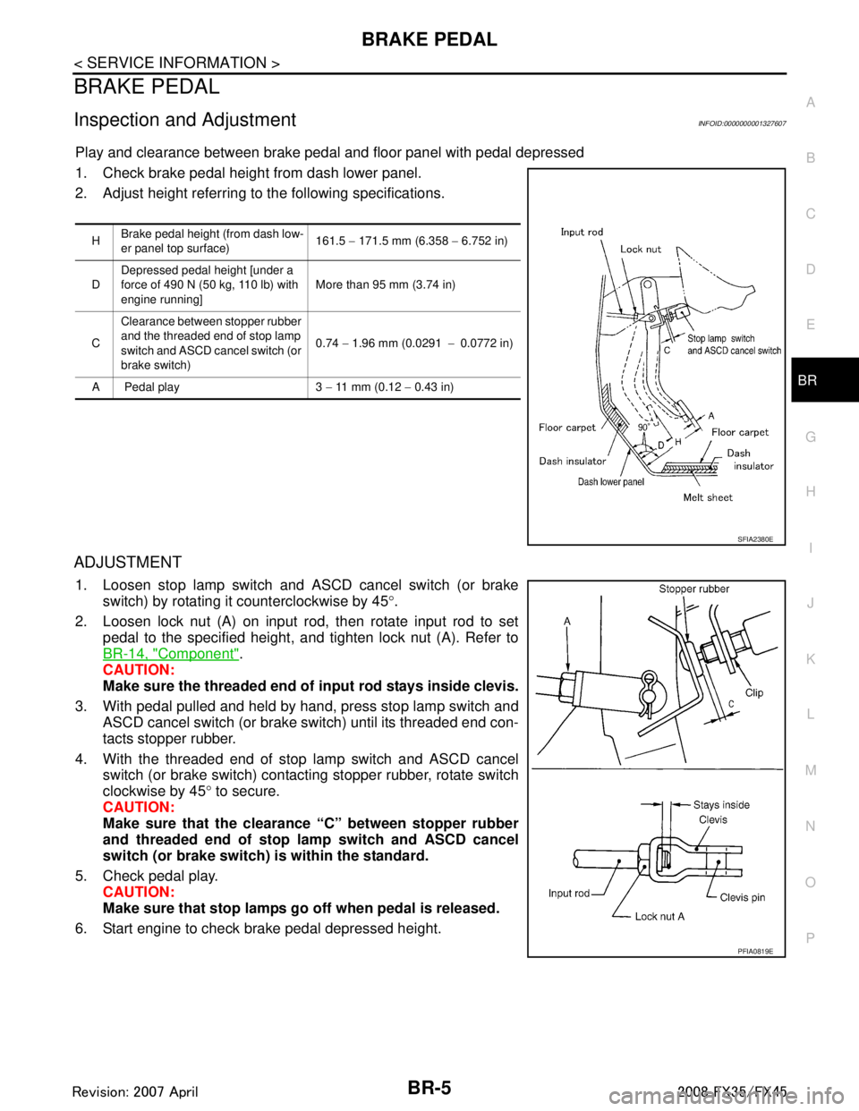
Play and clearance between brake pedal and floor panel with pedal depressed
1. Check brake pedal height from dash lower panel.
2. Adjust height referring to the following specifications.
ADJUSTMENT
1. Loosen stop lamp switch and ASCD cancel switch (or brake switch) by rotating it counterclockwise by 45 °.
2. Loosen lock nut (A) on input rod, then rotate input rod to set pedal to the specified height, and tighten lock nut (A). Refer to
BR-14, "
Component".
CAUTION:
Make sure the threaded end of input rod stays inside clevis.
3. With pedal pulled and held by hand, press stop lamp switch and ASCD cancel switch (or brake switch) until its threaded end con-
tacts stopper rubber.
4. With the threaded end of stop lamp switch and ASCD cancel switch (or brake switch) contacting stopper rubber, rotate switch
clockwise by 45 ° to secure.
CAUTION:
Make sure that the clearance “C” between stopper rubber
and threaded end of stop lamp switch and ASCD cancel
switch (or brake switch) is within the standard.
5. Check pedal play. CAUTION:
Make sure that stop lamps go off when pedal is released.
6. Start engine to check brake pedal depressed height.
H Brake pedal height (from dash low-
er panel top surface) 161.5
− 171.5 mm (6.358 − 6.752 in)
D Depressed pedal height [under a
force of 490 N (50 kg, 110 lb) with
engine running] More than 95 mm (3.74 in)
C Clearance between stopper rubber
and the threaded end of stop lamp
switch and ASCD cancel switch (or
brake switch) 0.74
− 1.96 mm (0.0291 −0.0772 in)
A Pedal play 3 − 11 mm (0.12 − 0.43 in)
SFIA2380E
PFIA0819E
3AA93ABC3ACD3AC03ACA3AC03AC63AC53A913A773A893A873A873A8E3A773A983AC73AC93AC03AC3
3A893A873A873A8F3A773A9D3AAF3A8A3A8C3A863A9D3AAF3A8B3A8C
Page 990 of 3924
BR-6
< SERVICE INFORMATION >
BRAKE PEDAL
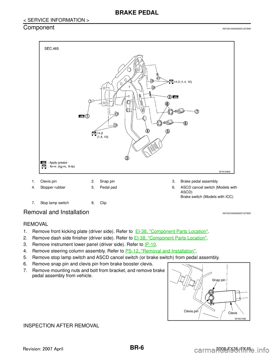
Component
INFOID:0000000001327608
Removal and InstallationINFOID:0000000001327609
REMOVAL
1. Remove front kicking plate (driver side). Refer to EI-38, "Component Parts Location".
2. Remove dash side finisher (driver side). Refer to EI-38, "
Component Parts Location".
3. Remove instrument lower panel (driver side). Refer to IP-10
.
4. Remove steering column assembly. Refer to PS-12, "
Removal and Installation".
5. Remove stop lamp switch and ASCD cancel s witch (or brake switch) from pedal assembly.
6. Remove snap pin and clevis pin from brake booster clevis.
7. Remove mounting nuts and bolt from bracket, and remove brake pedal assembly from vehicle.
INSPECTION AFTER REMOVAL
1. Clevis pin 2. Snap pin 3. Brake pedal assembly
4. Stopper rubber 5. Pedal pad 6. ASCD cancel switch (Models with
ASCD)
Brake switch (Models with ICC)
7. Stop lamp switch 8. Clip
SFIA1940E
SFIA0159E
3AA93ABC3ACD3AC03ACA3AC03AC63AC53A913A773A893A873A873A8E3A773A983AC73AC93AC03AC3
3A893A873A873A8F3A773A9D3AAF3A8A3A8C3A863A9D3AAF3A8B3A8C
Page 999 of 3924

BRAKE BOOSTERBR-15
< SERVICE INFORMATION >
C
DE
G H
I
J
K L
M A
B
BR
N
O P
CAUTION:
Be careful not to splash brake fluid on painted areas; it may cause paint damage. If brake fluid is
splashed on painted surfaces of body, immediately wipe it off and them wash it away with water
immediately.
Be careful not to deform or bend brake tube while removing and installing brake booster.
Replace clevis pin if it is damaged.
Be careful not to damage brake booster stud bolt thr eads. If brake booster is tilted or inclined during
installation, dash panel may damage the threads.
Install the check valve in the correct direction.
1. Remove vacuum hose from brake booster. Refer to BR-16
.
2. Remove brake master cylinder. Refer to BR-12, "
Removal and Installation".
3. Disconnect harness connector from brake booster assembly. (ICC model)
4. Remove snap pin and clevis pin from inside the vehicle. Refer to BR-6, "
Component".
5. Remove nuts from brake booster and brake pedal bracket.
6. Remove brake booster assembly from engine room.
INSPECTION AFTER REMOVAL
Output Rod Length Inspection
1. Using a handy vacuum pump, apply a vacuum of –66.7 kPa (– 500 mmHg, –19.69 inHg) to brake booster.
2. Check output rod length.
INSTALLATION
1. Loosen lock nut to adjust input r od length so that the length “B”
(shown in the figure) satisfies the specified value.
2. After adjusting “B”, temporarily tighten lock nut to install brake booster assembly to the vehicle. At this time, make sure to
install a gasket between brake booster assembly and the engine
room.
3. Connect brake pedal with clevis of input rod.
4. Install brake pedal bracket mounting nuts and bolt and tighten them to the specified torque. BR-6, "
Component".
5. Install brake tube from brake master cylinder to ABS actuator. Refer to BR-10, "
Hydraulic Circuit".
6. Install master cylinder to booster assembly. Refer to BR-12, "
Removal and Installation".
7. Adjust the height and play of brake pedal. BR-5, "
Inspection and Adjustment".
8. Tighten lock nut of input rod to the specified torque. Refer to BR-14, "
Component".
9. Bleed air. Refer to BR-8, "
Bleeding Brake System".
Standard dimension when
applying a vacuum of
− 66.7 kPa ( −500 mmHg, −19.69 inHg):
15.6 − 15.9 mm (0.614 − 0.626 in)
SFIA2146E
Length “B” : 126.5 mm (4.98 in)
SGIA0060E
3AA93ABC3ACD3AC03ACA3AC03AC63AC53A913A773A893A873A873A8E3A773A983AC73AC93AC03AC3
3A893A873A873A8F3A773A9D3AAF3A8A3A8C3A863A9D3AAF3A8B3A8C
Page 1014 of 3924

BR-30
< SERVICE INFORMATION >
SERVICE DATA AND SPECIFICATIONS (SDS)
SERVICE DATA AND SPECIFICATIONS (SDS)
General SpecificationINFOID:0000000001327639
Unit: mm (in)
Brake PedalINFOID:0000000001327640
Brake BoosterINFOID:0000000001327641
Vacuum type
Check ValveINFOID:0000000001327642
Front Disc BrakeINFOID:0000000001327643
Rear Disc BrakeINFOID:0000000001327644
Front brakeRotor outer diameter
× thickness 320 × 34 (12.598 × 1.339)
Pad length × width × thickness 130.0 × 50.0 × 11.0 (5.118 × 1.969 × 0.433)
Cylinder bore diameter 45.0 (1.772) × 2
Rear brake Rotor outer diameter
× thickness 308 × 16 (12.13 × 0.63)
Pad length × width × thickness 83.0 × 33.0 × 8.5 (3.268 × 1.299 × 0.335)
Cylinder bore diameter 42.86 (1.6874)
Master cylinder Cylinder bore diameter 25.4 (1.00)
Control valve Valve model Electric brake force distribution
Brake booster Diaphragm diameter Primary 228.5 (9.0)
Secondary 203.0 (8.0)
Recommended brake fluid DOT 3
Brake pedal height (from dash lower panel top surface) 161.5 − 171.5 mm (6.358 − 6.752 in)
Depressed pedal height
[under a force of 490 N (50 kg, 110 lb) with engine running] More than 95 mm (3.74 in)
Clearance between stopper rubber and the threaded end of stop lamp
switch and ASCD cancel switch (or brake switch) 0.74
− 1.96 mm (0.0291 − 0.0772 in)
Pedal play 3 − 11 mm (0.12 − 0.43 in)
Output rod length 15.6 − 15.9 mm (0.614 − 0.626 in)
Input rod length 126.5 mm (4.98 in)
Vacuum leakage
[at a vacuum of –66.7 kPa (–500 mmHg, –19.69 inHg)]Within vacuum of 1.3 kPa (10 mmHg, 0.39 inHg) for 15
seconds
Brake padStandard thickness 11.0 mm (0.433 in)
Repair limit thickness 2.0 mm (0.079 in)
Disc rotor Standard thickness 34.0 mm (1.339 in)
Wear limit 32.0 mm (1.260 in)
Maximum uneven wear (measured at 8 positions) 0.015mm (0.0006 in) or less
Runout limit (with the disc rotor attached to the vehicle) 0.04 mm (0.0016 in) or less
Brake pad
Standard thickness 8.5 mm (0.335 in)
Repair limit thickness 2.0 mm (0.079 in)
3AA93ABC3ACD3AC03ACA3AC03AC63AC53A913A773A893A873A873A8E3A773A983AC73AC93AC03AC3
3A893A873A873A8F3A773A9D3AAF3A8A3A8C3A863A9D3AAF3A8B3A8C
Page 1367 of 3924
![INFINITI FX35 2008 User Guide
TROUBLE DIAGNOSISEC-127
< SERVICE INFORMATION > [VQ35DE]
C
D
E
F
G H
I
J
K L
M A
EC
NP
O
2. Connect GST to data link connector, which is located under LH
dash panel near the hood opener handle.
3. Tu INFINITI FX35 2008 User Guide
TROUBLE DIAGNOSISEC-127
< SERVICE INFORMATION > [VQ35DE]
C
D
E
F
G H
I
J
K L
M A
EC
NP
O
2. Connect GST to data link connector, which is located under LH
dash panel near the hood opener handle.
3. Tu](/img/42/57017/w960_57017-1366.png)
TROUBLE DIAGNOSISEC-127
< SERVICE INFORMATION > [VQ35DE]
C
D
E
F
G H
I
J
K L
M A
EC
NP
O
2. Connect GST to data link connector, which is located under LH
dash panel near the hood opener handle.
3. Turn ignition switch ON.
4. Enter the program according to instruction on the screen or in the operation manual.
(*: Regarding GST screens in this section, sample screens are
shown.)
5. Perform each diagnostic mode according to each service proce- dure.
For further information, see th e GST Operation Manual of
the tool maker.
CONSULT-III Reference Val ue in Data Monitor ModeINFOID:0000000001325938
Remarks:
● Specification data are reference values.
● Specification data are output/input values which ar e detected or supplied by the ECM at the connector.
* Specification data may not be directly relat ed to their components signals/values/operations.
i.e. Adjust ignition timing with a timi ng light before monitoring IGN TIMING, because the monitor may show the specification data in spite of the
ignition timing not being adjusted to the s pecification data. This IGN TIMING monitors the data calculated by the ECM according to the signals
input from the camshaft position sensor an d other ignition timing related sensors.
PBIB1570E
SEF398S
SEF416S
MONITOR ITEM CONDITION SPECIFICATION
ENG SPEED Run engine and compare CONSULT-III value with the tachometer indica-
tion. Almost the same speed as the
tachometer indication.
MAS A/F SE-B1 See EC-131
.
B/FUEL SCHDL See EC-131
.
A/F ALPHA-B1
A/F ALPHA-B2 See
EC-131
.
COOLAN TEMP/S Engine: After warming up More than 70 °C (158 °F)
A/F SEN1 (B1)
A/F SEN1 (B2) Engine: After warming up Maintaining engine speed at 2,000 rpm Fluctuates around 1.5 V
3AA93ABC3ACD3AC03ACA3AC03AC63AC53A913A773A893A873A873A8E3A773A983AC73AC93AC03AC3
3A893A873A873A8F3A773A9D3AAF3A8A3A8C3A863A9D3AAF3A8B3A8C
Page 1945 of 3924
![INFINITI FX35 2008 User Guide
TROUBLE DIAGNOSISEC-705
< SERVICE INFORMATION > [VK45DE]
C
D
E
F
G H
I
J
K L
M A
EC
NP
O
INSPECTION PROCEDURE
1. Turn ignition switch OFF.
2. Connect “GST” to data link connector, which is locate INFINITI FX35 2008 User Guide
TROUBLE DIAGNOSISEC-705
< SERVICE INFORMATION > [VK45DE]
C
D
E
F
G H
I
J
K L
M A
EC
NP
O
INSPECTION PROCEDURE
1. Turn ignition switch OFF.
2. Connect “GST” to data link connector, which is locate](/img/42/57017/w960_57017-1944.png)
TROUBLE DIAGNOSISEC-705
< SERVICE INFORMATION > [VK45DE]
C
D
E
F
G H
I
J
K L
M A
EC
NP
O
INSPECTION PROCEDURE
1. Turn ignition switch OFF.
2. Connect “GST” to data link connector, which is located under LH
dash panel near the hood opener handle.
3. Turn ignition switch ON.
4. Enter the program according to instruction on the screen or in the operation manual.
(*: Regarding GST screens in this section, sample screens are
shown.)
5. Perform each diagnostic mode according to each service proce- dure.
For further information, see th e GST Operation Manual of
the tool maker.
CONSULT-III Reference Val ue in Data Monitor ModeINFOID:0000000001326534
Remarks:
Service $07 (ON BOARD TESTS) This mode enables the off board test drive to obtain test results for emission-related pow-
ertrain components/systems that are continuously monitored during normal driving condi-
tions.
Service $08 — This mode can close EVAP system in ignition switch ON position (Engine stopped). When
this mode is performed, EVAP canister vent control valve can be closed.
In the following conditions, this mode cannot function.
Low ambient temperature
Low battery voltage
Engine running
Ignition switch OFF
Low fuel temperature
Too much pressure is applied to EVAP system
Service $09 (CALIBRATION ID) This mode enables the off-board test device to request specific vehicle information such
as Vehicle Identification Number (VIN) and Calibration IDs.
Diagnostic service Function
PBIB1503E
SEF398S
SEF416S
3AA93ABC3ACD3AC03ACA3AC03AC63AC53A913A773A893A873A873A8E3A773A983AC73AC93AC03AC3
3A893A873A873A8F3A773A9D3AAF3A8A3A8C3A863A9D3AAF3A8B3A8C
Page 2475 of 3924
EI-38
< SERVICE INFORMATION >
BODY SIDE TRIM
BODY SIDE TRIM
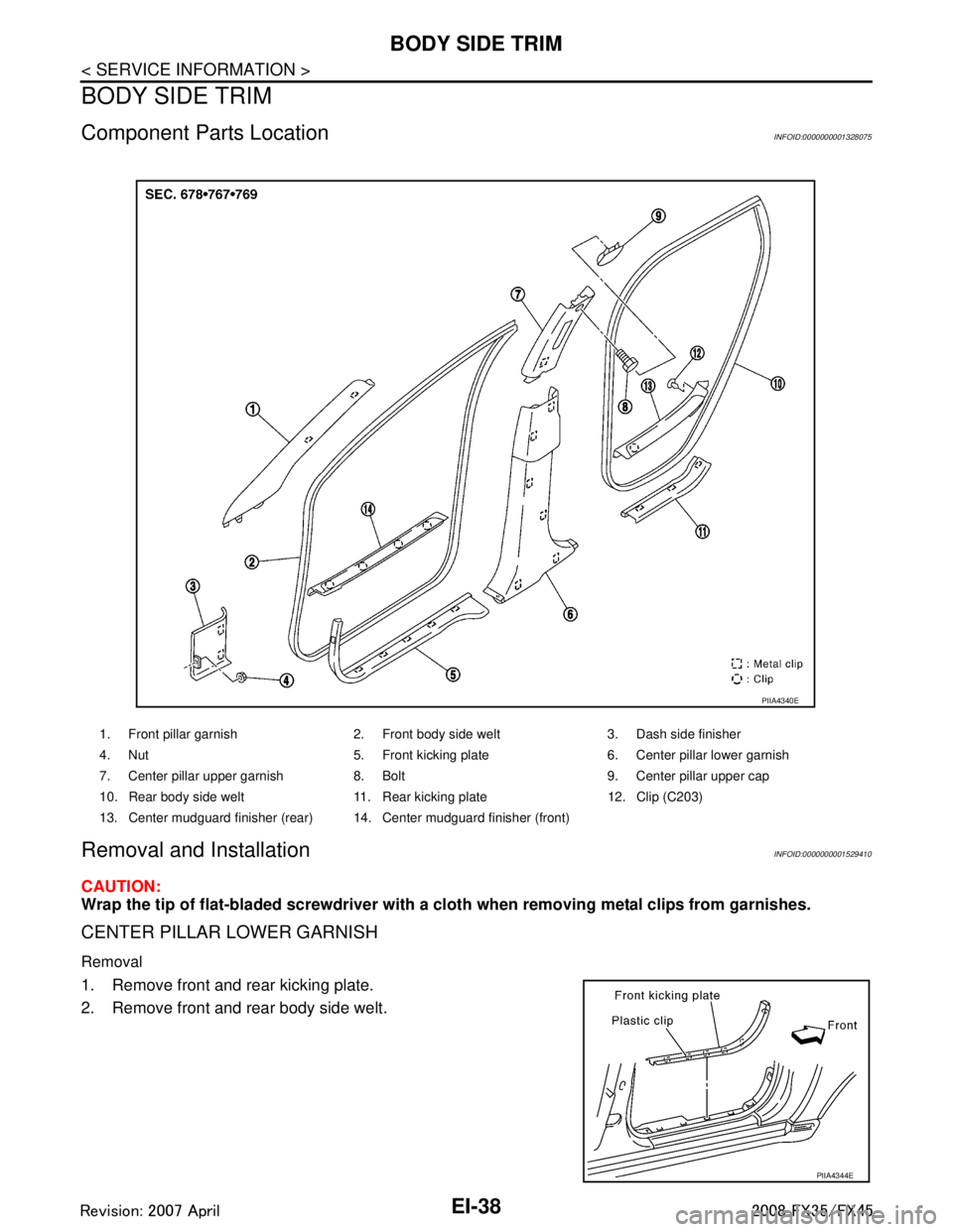
Component Parts LocationINFOID:0000000001328075
Removal and InstallationINFOID:0000000001529410
CAUTION:
Wrap the tip of flat-bladed screwdriver with a cloth when removing metal clips from garnishes.
CENTER PILLAR LOWER GARNISH
Removal
1. Remove front and rear kicking plate.
2. Remove front and rear body side welt.
1. Front pillar garnish 2. Front body side welt 3. Dash side finisher
4. Nut 5. Front kicking plate 6. Center pillar lower garnish
7. Center pillar upper garnish 8. Bolt 9. Center pillar upper cap
10. Rear body side welt 11. Rear kicking plate 12. Clip (C203)
13. Center mudguard finisher (rear) 14. Center mudguard finisher (front)
PIIA4340E
PIIA4344E
3AA93ABC3ACD3AC03ACA3AC03AC63AC53A913A773A893A873A873A8E3A773A983AC73AC93AC03AC3
3A893A873A873A8F3A773A9D3AAF3A8A3A8C3A863A9D3AAF3A8B3A8C
Page 2476 of 3924
BODY SIDE TRIMEI-39
< SERVICE INFORMATION >
C
DE
F
G H
J
K L
M A
B
EI
N
O P
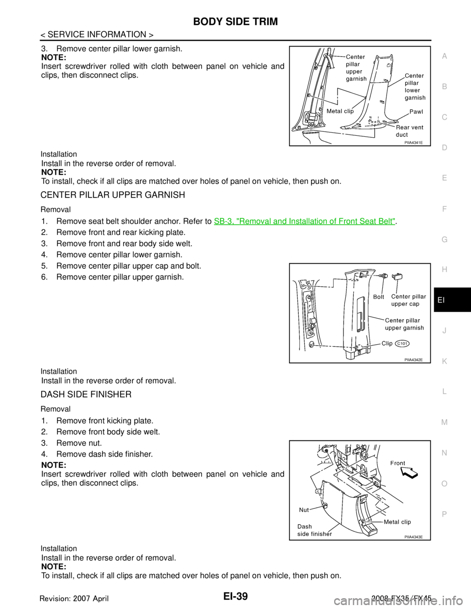
3. Remove center pillar lower garnish.
NOTE:
Insert screwdriver rolled with cloth between panel on vehicle and
clips, then disconnect clips.
Installation
Install in the reverse order of removal.
NOTE:
To install, check if all clips are matched over holes of panel on vehicle, then push on.
CENTER PILLAR UPPER GARNISH
Removal
1. Remove seat belt shoulder anchor. Refer to SB-3, "Removal and Installation of Front Seat Belt".
2. Remove front and rear kicking plate.
3. Remove front and rear body side welt.
4. Remove center pillar lower garnish.
5. Remove center pillar upper cap and bolt.
6. Remove center pillar upper garnish.
Installation
Install in the reverse order of removal.
DASH SIDE FINISHER
Removal
1. Remove front kicking plate.
2. Remove front body side welt.
3. Remove nut.
4. Remove dash side finisher.
NOTE:
Insert screwdriver rolled with cloth between panel on vehicle and
clips, then disconnect clips.
Installation
Install in the reverse order of removal.
NOTE:
To install, check if all clips are matched over holes of panel on vehicle, then push on.
PIIA4341E
PIIA4342E
PIIA4343E
3AA93ABC3ACD3AC03ACA3AC03AC63AC53A913A773A893A873A873A8E3A773A983AC73AC93AC03AC3
3A893A873A873A8F3A773A9D3AAF3A8A3A8C3A863A9D3AAF3A8B3A8C
Page 2478 of 3924
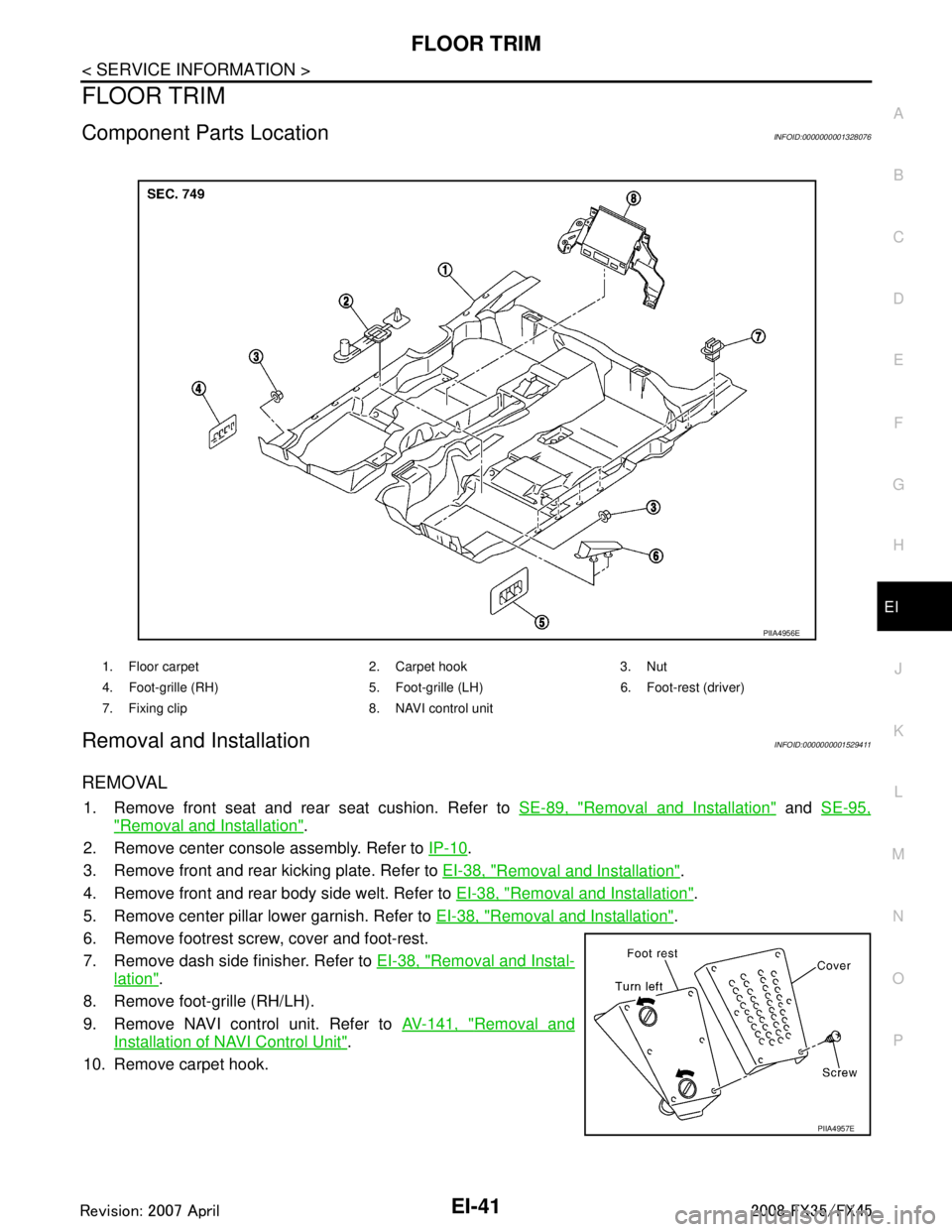
FLOOR TRIMEI-41
< SERVICE INFORMATION >
C
DE
F
G H
J
K L
M A
B
EI
N
O P
FLOOR TRIM
Component Parts LocationINFOID:0000000001328076
Removal and InstallationINFOID:0000000001529411
REMOVAL
1. Remove front seat and rear seat cushion. Refer to SE-89, "Removal and Installation" and SE-95,
"Removal and Installation".
2. Remove center console assembly. Refer to IP-10
.
3. Remove front and rear kicking plate. Refer to EI-38, "
Removal and Installation".
4. Remove front and rear body side welt. Refer to EI-38, "
Removal and Installation".
5. Remove center pillar lower garnish. Refer to EI-38, "
Removal and Installation".
6. Remove footrest screw, cover and foot-rest.
7. Remove dash side finisher. Refer to EI-38, "
Removal and Instal-
lation".
8. Remove foot-grille (RH/LH).
9. Remove NAVI control unit. Refer to AV-141, "
Removal and
Installation of NAVI Control Unit".
10. Remove carpet hook.
1. Floor carpet 2. Carpet hook 3. Nut
4. Foot-grille (RH) 5. Foot-gri lle (LH) 6. Foot-rest (driver)
7. Fixing clip 8. NAVI control unit
PIIA4956E
PIIA4957E
3AA93ABC3ACD3AC03ACA3AC03AC63AC53A913A773A893A873A873A8E3A773A983AC73AC93AC03AC3
3A893A873A873A8F3A773A9D3AAF3A8A3A8C3A863A9D3AAF3A8B3A8C
Page 2597 of 3924
![INFINITI FX35 2008 User Guide
ENGINE ASSEMBLYEM-113
< SERVICE INFORMATION > [VQ35DE]
C
D
E
F
G H
I
J
K L
M A
EM
NP
O
At first, remove the engine and the transmission asse
mbly with front suspension member downward. Then
separate INFINITI FX35 2008 User Guide
ENGINE ASSEMBLYEM-113
< SERVICE INFORMATION > [VQ35DE]
C
D
E
F
G H
I
J
K L
M A
EM
NP
O
At first, remove the engine and the transmission asse
mbly with front suspension member downward. Then
separate](/img/42/57017/w960_57017-2596.png)
ENGINE ASSEMBLYEM-113
< SERVICE INFORMATION > [VQ35DE]
C
D
E
F
G H
I
J
K L
M A
EM
NP
O
At first, remove the engine and the transmission asse
mbly with front suspension member downward. Then
separate the engine from transmission.
Preparation
1. Release fuel pressure. Refer to EC-87, "Fuel Pressure Check".
2. Drain engine coolant from radiator. Refer to CO-10, "
Changing Engine Coolant".
CAUTION:
Perform this step when engine is cold.
Do not spill engine coolant on drive belts.
3. Disconnect both battery terminals. Refer to SC-4, "
How to Handle Battery".
4. Remove the following parts: Engine cover: Refer to EM-19, "
Component".
Front road wheel and tires
Front and rear engine undercover
Front cross bar: Refer to FSU-16, "
Removal and Installation".
Cowl top cover (right): Refer to EI-23, "
Component Parts Location".
Air duct and air cleaner case assembly: EM-17, "
Component".
5. Discharge refrigerant from A/C circuit. Refer to ATC-120, "
HFC-134a (R-134a) Service Procedure".
6. Remove radiator hoses (upper and lower). Refer to CO-13, "
Component".
Engine Room
1. Disconnect heater hose from vehicle-side, and fit a plug onto hose end to prevent engine coolant leak.
2. Disconnect grounding cable (between vehicle to left bank cylinder head).
3. Disconnect battery positive cable harness at v ehicle side and temporarily fasten it on engine.
4. Disconnect A/C piping from A/C compressor, and tem porarily fasten it on vehicle with a rope. Refer to
ATC-120, "
HFC-134a (R-134a) Service Procedure".
5. Disconnect engine room harness connectors shown in the fig- ure.
6. Disconnect two body ground cables.
7. Disconnect brake booster vacuum hose.
8. Disconnect fuel feed hose (with damper) and EVAP hose. Refer to EM-45, "
Component".
CAUTION:
Fit plugs onto disconnected hoses to prevent fuel leak.
9. Remove reservoir tank of power steering oil pump and piping from vehicle, and temporarily secure them
on engine. Refer to PS-27, "
On-Vehicle Inspection and Service".
CAUTION:
When temporarily securing, keep the reservo ir tank upright to avoid a fluid leak.
Passenger Room Side
Follow procedure below to disconnect engine room harne ss connectors at passenger room side, and tempo-
rarily secure them on engine.
1. Remove passenger-side kicking plate, dash side finisher, and glove box. Refer to EI-38, "
Component
Parts Location" and IP-10, "Component Parts Location".
SBIA0472E
3AA93ABC3ACD3AC03ACA3AC03AC63AC53A913A773A893A873A873A8E3A773A983AC73AC93AC03AC3
3A893A873A873A8F3A773A9D3AAF3A8A3A8C3A863A9D3AAF3A8B3A8C