dash INFINITI FX35 2008 Service Manual
[x] Cancel search | Manufacturer: INFINITI, Model Year: 2008, Model line: FX35, Model: INFINITI FX35 2008Pages: 3924, PDF Size: 81.37 MB
Page 733 of 3924

BCM (BODY CONTROL MODULE)BCS-13
< SERVICE INFORMATION >
C
DE
F
G H
I
J
L
M A
B
BCS
N
O P
SELF-DIAG RESULTS
U1000 CAN Communication CircuitINFOID:0000000001606767
1.PERFORM SELF DIAGNOSTIC
1. Turn ignition switch ON and wait for 2 seconds or more.
2. Check “Self Diagnostic Result” of BCM.
Is
“CAN COMM CIRCUIT” displayed?
YES >> Refer to LAN-14, "Trouble Diagnosis Flow Chart".
NO >> Refer to GI-25, "
How to Perform Efficient Diagnosis for an Electrical Incident".
Removal and Installation of BCMINFOID:0000000001328613
REMOVAL
1. Remove the dash side finisher (LH). Refer to EI-38.
2. Disconnect BCM connector.
3. Remove bracket mounting screws (3) to remove BCM and fuse block with bracket.
Item Description
RESET SETTING VALUE Return a value set with WORK SUPPORT of each system to a default value in factory shipment.
DTC DTC Detection Condition Possible cause
U1000: CAN COMM CIRCUIT When BCM cannot communicate CAN com-
munication signal continuously for 2 sec-
onds or more. Any item (or items) of the following listed below is
malfunctioning in CAN communication system.
Transmission
Receiving (ECM)
Receiving (IPDM E/R)
Receiving (METER/M&A)
Receiving (I-KEY)
SKIA4964E
3AA93ABC3ACD3AC03ACA3AC03AC63AC53A913A773A893A873A873A8E3A773A983AC73AC93AC03AC3
3A893A873A873A8F3A773A9D3AAF3A8A3A8C3A863A9D3AAF3A8B3A8C
Page 749 of 3924

HOODBL-15
< SERVICE INFORMATION >
C
DE
F
G H
J
K L
M A
B
BL
N
O P
1. Support the hood striker with a proper material to prevent it from falling.
WARNING:
Body injury may occur if no supporting rod is holding the
hood open when removi ng the hood stay.
2. Remove the hood stays from the stud balls on the body side.
3. Remove the hinge mounting nuts on the hood to remove the hood assembly.
CAUTION:
Operate with two workers, because of its heavy weight.
INSTALLATION
Install in the reverse order of removal.
Removal and Installation of Hood Lock ControlINFOID:0000000001327785
REMOVAL
1. Remove the front grill. Refer to EI-22, "Component Parts Location".
2. Remove the front fender protector (LH). Refer to EI-24, "
Component Parts Location".
3. Disconnect the hood lock cable from the hood lock, and c lip it from the radiator core support upper and
hood ledge.
4. Remove instrument driver lower panel. Refer to IP-11, "
Removal and Installation".
5. After the bolt of the case with the air cleaner is disconnected, and it is moved, the cable is pulled.
PIIA6058E
1. Hood lock 2. Hood lock cable 3. Clip
4. Hood ledge upper front (LH) 5. Dash lower cross member reinforce (LH)
PIIA6017E
3AA93ABC3ACD3AC03ACA3AC03AC63AC53A913A773A893A873A873A8E3A773A983AC73AC93AC03AC3
3A893A873A873A8F3A773A9D3AAF3A8A3A8C3A863A9D3AAF3A8B3A8C
Page 750 of 3924

BL-16
< SERVICE INFORMATION >
HOOD
6. Remove the grommet on the dashboard, and pull the hood lock cable toward the passenger room.CAUTION:
While pulling, be careful not to damage (p eeling) the outside of the hood lock cable.
INSTALLATION
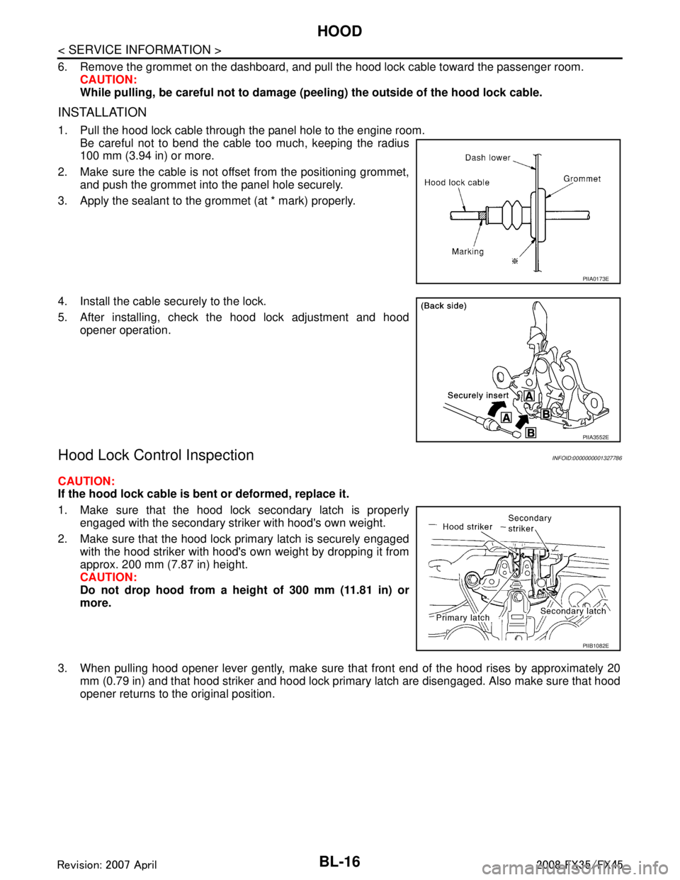
1. Pull the hood lock cable through the panel hole to the engine room.
Be careful not to bend the cable too much, keeping the radius
100 mm (3.94 in) or more.
2. Make sure the cable is not offset from the positioning grommet, and push the grommet into the panel hole securely.
3. Apply the sealant to the grommet (at * mark) properly.
4. Install the cable securely to the lock.
5. After installing, check the hood lock adjustment and hood opener operation.
Hood Lock Control InspectionINFOID:0000000001327786
CAUTION:
If the hood lock cable is bent or deformed, replace it.
1. Make sure that the hood lock secondary latch is properlyengaged with the secondary striker with hood's own weight.
2. Make sure that the hood lock primary latch is securely engaged with the hood striker with hood's own weight by dropping it from
approx. 200 mm (7.87 in) height.
CAUTION:
Do not drop hood from a he ight of 300 mm (11.81 in) or
more.
3. When pulling hood opener lever gently, make sure that front end of the hood rises by approximately 20 mm (0.79 in) and that hood striker and hood lock primary latch are disengaged. Also make sure that hood
opener returns to the original position.
PIIA0173E
PIIA3552E
PIIB1082E
3AA93ABC3ACD3AC03ACA3AC03AC63AC53A913A773A893A873A873A8E3A773A983AC73AC93AC03AC3
3A893A873A873A8F3A773A9D3AAF3A8A3A8C3A863A9D3AAF3A8B3A8C
Page 833 of 3924

INTELLIGENT KEY SYSTEMBL-99
< SERVICE INFORMATION >
C
DE
F
G H
J
K L
M A
B
BL
N
O P
Terminal and Reference Valu e for INTELLIGENT KEY UNITINFOID:0000000001327842
Te r -
minal Wire
color Item Signal
Input/
output Condition
Voltage (V)(Approx.)
Ignition
knob po- sition Operation or conditions
1R/W Steering lock unit power
supply
Output LOCK — 5
2 L CAN-H Input/
Output —— —
3 P CAN-L Input/
Output —— —
4LG Intelligent Key warning
buzzer Output LOCKOperate remote
controller button or door request switch. Buzzer OFF Battery voltage
Sound
buzzer
0
5W/L Door request switch
(driver side) Input —Door request switch operation:
Press (ON).
0
Other than the above (OFF) 5
6 W Ignition switch (ON) Input ON or
START — Battery voltage
7 B/W key switch Input LOCK Insert mechanical key into igni-
tion key cylinder.
Battery voltage
Remove mechanical key from ig-
nition key cylinder. 0
10 LG Ignition switch (ACC) Input ACC or
ON — Battery voltage
11 L/R Power source (Fuse) Input — — Battery voltage
12 B Ground — — — 0
13 P Inside key antenna (+)
(Luggage room) Output
LOCKAny door open
→ all doors shut
(Door switch: ON → OFF)
14 L Inside key antenna (-)
(Luggage room)
Output
15 G Inside key antenna (+)
signal
(Dashboard) Output
LOCKAny door open
→ Close (Door
switch: ON → OFF)
Ignition knob switch: ON (press
ignition knob.)
16 R Inside key
antenna (-)
signal
(Dashboard) Output
17 L Back door antenna (+) Output
LOCKBack door request switch opera-
tion (Switch: ON)
18 W/L Back door antenna (-) Output
SIIA1910J
SIIA1910J
SIIA1910J
3AA93ABC3ACD3AC03ACA3AC03AC63AC53A913A773A893A873A873A8E3A773A983AC73AC93AC03AC3
3A893A873A873A8F3A773A9D3AAF3A8A3A8C3A863A9D3AAF3A8B3A8C
Page 834 of 3924

BL-100
< SERVICE INFORMATION >
INTELLIGENT KEY SYSTEM
19 SB Outside antenna LH (+) OutputLOCKDriver door request signal opera-
tion (Switch: ON)
20 G/Y Outside antenna LH (-) Output
25 W/R Door request switch
(passenger side)
Input —Door request switch operation:
Press (ON)
0
Other than the above (OFF) 5
26 P/L Stop lamp switch Input — Brake pedal depressed (ON) 5
Brake pedal not depressed
(OFF)
0
27 L/W Ignition knob switch Input — Press ignition knob. 12
Return ignition knob to LOCK po-
sition.
0
28 W/B Door unlock sensor Input — Door is locking → unlock 5 → 0
29 GY Door request switch
(back door)
Input —Back door request switch opera-
tion: Press (ON)
0
Other than the above (OFF) 5
31 Y/B Steering lock unit
ground —— — 0
32 R/B Steering lock unit com-
munication Output LOCKPress ignition knob with Intelli-
gent Key inside vehicle.
Other than the above 5
35 LG Inside key antenna (+)
signal
(Dashboard) Output
LOCKAny door open
→ Close (Door
switch: ON → OFF)
Ignition knob switch: ON (press
ignition knob.)
36 PU Inside key antenna (-)
signal
(Dashboard) Output
37 G Outside antenna RH (+) Output
LOCKPassenger door request switch
operation (Switch: ON)
38 G/W Outside antenna RH (-) Output
Te r -
minal Wire
color Item Signal
Input/
output Condition
Voltage (V)(Approx.)
Ignition
knob po-
sition Operation or conditions
SIIA1910J
SIIA1911J
SIIA1910J
SIIA1910J
3AA93ABC3ACD3AC03ACA3AC03AC63AC53A913A773A893A873A873A8E3A773A983AC73AC93AC03AC3
3A893A873A873A8F3A773A9D3AAF3A8A3A8C3A863A9D3AAF3A8B3A8C
Page 857 of 3924

INTELLIGENT KEY SYSTEMBL-123
< SERVICE INFORMATION >
C
DE
F
G H
J
K L
M A
B
BL
N
O P
OK or NG
OK >> Replace Intelligent Key unit.
NG >> Replace harness between outside key antenna and Intelligent Key unit.
Check Inside Key AntennaINFOID:0000000001327862
1.CHECK INSIDE KEY ANTENNA POWER SUPPLY CIRCUIT
Push ignition knob and use an oscilloscope to check voltage waveform between Intelligent Key unit connector
M34 terminals 13 (luggage room), 15 (dash board), 35 (dash board) and ground.
OK or NG
OK >> GO TO 2.
NG >> GO TO 3.
2.CHECK INSIDE KEY ANTENNA OPERATION
1. Disconnect inside key antenna connector.
2. Check continuity between inside key antenna c onnector M70, M153 (dash board), B68 (luggage room)
terminals 1 and 2.
OK or NG
OK >> GO TO 3.
NG >> Replace malfunctioning inside key antenna.
3.CHECK INSIDE KEY ANTENNA
1. Disconnect Intelligent Key unit connector.
2. Check continuity between inside key antenna c onnector M70, M153 (dash board), B68 (luggage room)
terminals 1, 2 and Intelligent Key unit connector terminals 13, 14, 15, 16, 35 and 36.
Back door 1 (L/B)
Ground No
2 (W/B)
Rear door
(LH, RH) 1 (G/Y)
2 (PU/W)
Driver side 14 (BR/W)
15 (R/Y)
Passenger side 14 (G/Y)
15 (L/Y)
Terminal (Wire color) ConditionSignal
(Reference value)
(+) (-)
Luggage room:
13 (P)
GroundPush ignition
knob.
Dash board:
15 (G)
35 (LG)
PIIA6753ESIIA1910J
1 - 2 : Continuity should exist.
PIIB8512E
3AA93ABC3ACD3AC03ACA3AC03AC63AC53A913A773A893A873A873A8E3A773A983AC73AC93AC03AC3
3A893A873A873A8F3A773A9D3AAF3A8A3A8C3A863A9D3AAF3A8B3A8C
Page 858 of 3924

BL-124
< SERVICE INFORMATION >
INTELLIGENT KEY SYSTEM
3. Check continuity between inside key antenna connector M70,M153 (dash board), B68 (luggage room) terminals 1 and 2 and
ground.
OK or NG
OK >> Replace Intelligent Key unit.
NG >> Repair or replace harness between inside key antenna and Intelligent Key unit.
Check Steering Lock UnitINFOID:0000000001327863
1.CHECK STEERING LOCK UNIT POWER SUPPLY
1. Turn ignition knob LOCK position.
2. Disconnect steering lock unit connector.
3. Check voltage between steering lock uni t connector M26 terminal 1 (L/R) and ground.
OK or NG
OK >> GO TO 2.
NG >> Repair or replace steering lock unit power supply circuit.
2.CHECK STEERING LOCK UNIT GROUND CIRCUIT
Check continuity between steering lock unit connector M26 terminal 4 (Y/B) and ground.
OK or NG
OK >> GO TO 3.
NG >> GO TO 4.
Item Terminal Continuity
Inside key antenna-3 (Luggage room) 1 (OR/L) 13 (P)
Ye s
2 (W/L) 14 (L)
Inside key antenna-1 (Dash board) 1 (G) 15 (G)
2 (R) 16 (R)
Inside key antenna-2 (Dash board) 1 (LG) 35 (LG)
2 (PU) 36 (PU)
Item Terminal Continuity
Inside key antenna-3 (Luggage room) 1 (OR/L)
Ground No
2 (W/L)
Inside key antenna-1 (Dash board) 1 (G)
2 (R)
Inside key antenna-2 (Dash board) 1 (LG)
2 (PU)
PIIB8513E
1 (L/R) - Ground : Battery voltage
PIIA6797E
4 (Y/B) - Ground : Continuity should exist.
PIIA6798E
3AA93ABC3ACD3AC03ACA3AC03AC63AC53A913A773A893A873A873A8E3A773A983AC73AC93AC03AC3
3A893A873A873A8F3A773A9D3AAF3A8A3A8C3A863A9D3AAF3A8B3A8C
Page 939 of 3924

BODY REPAIRBL-205
< SERVICE INFORMATION >
C
DE
F
G H
J
K L
M A
B
BL
N
O P
Body Component PartsINFOID:0000000001327944
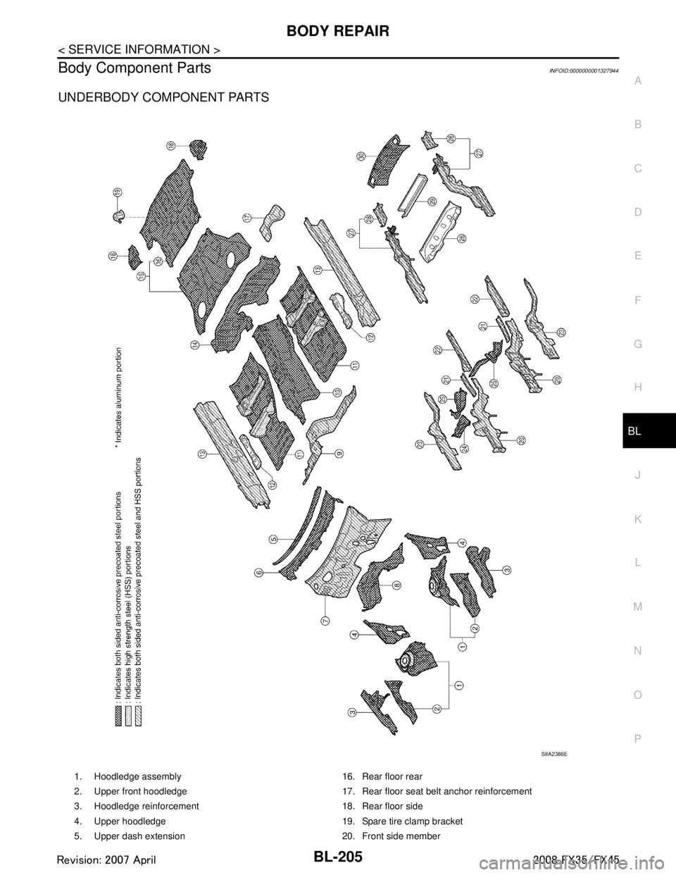
UNDERBODY COMPONENT PARTS
SIIA2386E
1. Hoodledge assembly 16. Rear floor rear
2. Upper front hoodledge 17. Rear floor seat belt anchor reinforcement
3. Hoodledge reinforcement 18. Rear floor side
4. Upper hoodledge 19. Spare tire clamp bracket
5. Upper dash extension 20. Front side member
3AA93ABC3ACD3AC03ACA3AC03AC63AC53A913A773A893A873A873A8E3A773A983AC73AC93AC03AC3
3A893A873A873A8F3A773A9D3AAF3A8A3A8C3A863A9D3AAF3A8B3A8C
Page 940 of 3924

BL-206
< SERVICE INFORMATION >
BODY REPAIR
6. Upper dash crossmember assembly 21. Front side member rear reinforcement
7. Upper dash assembly 22. Front side member front extension
8. Front cowl top assembly 23. Front side member closing plate
9. Lower dash 24. Front side member outrigger assembly (RH&LH)
10. Front floor center 25. Front crossmember
11. Front floor 26. 2ND rear crossmember
12. Front floor reinforcement 27. Rear side member assembly
13. Inner sill 28. Rear side member extension
14. Lower rear seat crossmember 29. Rear center crossmember assembly
15. Rear floor front 30. Rear end crossmember assembly
3AA93ABC3ACD3AC03ACA3AC03AC63AC53A913A773A893A873A873A8E3A773A983AC73AC93AC03AC3
3A893A873A873A8F3A773A9D3AAF3A8A3A8C3A863A9D3AAF3A8B3A8C
Page 962 of 3924

BL-228
< SERVICE INFORMATION >
BODY REPAIR
Precaution in Repairing High Strength Steel
INFOID:0000000001327950
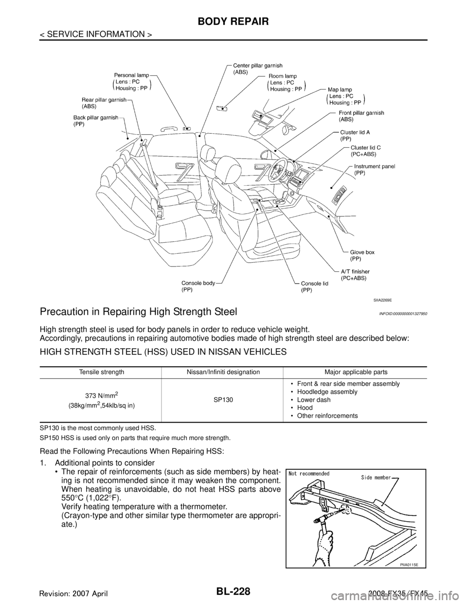
High strength steel is used for body panels in order to reduce vehicle weight.
Accordingly, precautions in repairing automotive bodies made of high strength steel are described below:
HIGH STRENGTH STEEL (HSS) USED IN NISSAN VEHICLES
SP130 is the most commonly used HSS.
SP150 HSS is used only on parts that require much more strength.
Read the Following Precautions When Repairing HSS:
1. Additional points to consider
The repair of reinforcements (such as side members) by heat-
ing is not recommended since it may weaken the component.
When heating is unavoidable, do not heat HSS parts above
550 °C (1,022 °F).
Verify heating temperature with a thermometer.
(Crayon-type and other similar type thermometer are appropri-
ate.)
SIIA2269E
Tensile strength Nissan/Infiniti designation Major applicable parts
373 N/mm
2
(38kg/mm2,54klb/sq in) SP130 Front & rear side member assembly
Hoodledge assembly
Lower dash
Hood
Other reinforcements
PIIA0115E
3AA93ABC3ACD3AC03ACA3AC03AC63AC53A913A773A893A873A873A8E3A773A983AC73AC93AC03AC3
3A893A873A873A8F3A773A9D3AAF3A8A3A8C3A863A9D3AAF3A8B3A8C