reset INFINITI FX35 2008 Owner's Manual
[x] Cancel search | Manufacturer: INFINITI, Model Year: 2008, Model line: FX35, Model: INFINITI FX35 2008Pages: 3924, PDF Size: 81.37 MB
Page 1850 of 3924
![INFINITI FX35 2008 Owners Manual
EC-610
< SERVICE INFORMATION >[VK45DE]
ENGINE CONTROL SYSTEM
*1: This sensor is not used to control the engine system under normal conditions.
*2: This signal is sent to the ECM through CAN communica INFINITI FX35 2008 Owners Manual
EC-610
< SERVICE INFORMATION >[VK45DE]
ENGINE CONTROL SYSTEM
*1: This sensor is not used to control the engine system under normal conditions.
*2: This signal is sent to the ECM through CAN communica](/img/42/57017/w960_57017-1849.png)
EC-610
< SERVICE INFORMATION >[VK45DE]
ENGINE CONTROL SYSTEM
*1: This sensor is not used to control the engine system under normal conditions.
*2: This signal is sent to the ECM through CAN communication line.
*3: ECM determines the start signal status by the signals of engine speed and battery voltage.
SYSTEM DESCRIPTION
The amount of fuel injected from the fuel injector is
determined by the ECM. The ECM controls the length of
time the valve remains open (injection pulse duration). T he amount of fuel injected is a program value in the
ECM memory. The program value is preset by engi ne operating conditions. These conditions are determined
by input signals (for engine speed and intake air) from t he crankshaft position sensor (POS), camshaft position
sensor (PHASE) and the ma ss air flow sensor.
VARIOUS FUEL INJECTION I NCREASE/DECREASE COMPENSATION
In addition, the amount of fuel injected is compens ated to improve engine performance under various operat-
ing conditions as listed below.
When starting the engine
During acceleration
Hot-engine operation
When selector lever is changed from N to D
High-load, high-speed operation
During high engine speed operation
MIXTURE RATIO FEEDBACK CONTROL (CLOSED LOOP CONTROL)
Sensor Input Signal to ECM ECM function Actuator
Crankshaft position sensor (POS) Engine speed*
3
Piston position
Fuel injection
& mixture ratio
controlFuel injector
Camshaft position sensor (PHASE)
Mass air flow sensor Amount of intake air
Engine coolant temperature sensor Engine coolant temperature
Air fuel ratio (A/F) sensor 1 Density of oxygen in exhaust gas
Throttle position sensor Throttle position
Accelerator pedal position sensor Accelerator pedal position
Park/neutral position (PNP) switch Gear position
Battery
Battery voltage*
3
Knock sensor Engine knocking condition
Power steering pressure sensor Power steering operation
Heated oxygen sensor 2*
1Density of oxygen in exhaust gas
ABS actuator and electric unit (control unit) VDC/TCS operation command*
2
Air conditioner switch Air conditioner operation
Wheel sensorVehicle speed*
2
PBIB3020E
3AA93ABC3ACD3AC03ACA3AC03AC63AC53A913A773A893A873A873A8E3A773A983AC73AC93AC03AC3
3A893A873A873A8F3A773A9D3AAF3A8A3A8C3A863A9D3AAF3A8B3A8C
Page 1892 of 3924
![INFINITI FX35 2008 Owners Manual
EC-652
< SERVICE INFORMATION >[VK45DE]
ON BOARD DIAGNOSTIC (OBD) SYSTEM
tified codes can be identified by using the CONSULT-II
I or GST. A DTC will be used as an example for how to
read a code.
A par INFINITI FX35 2008 Owners Manual
EC-652
< SERVICE INFORMATION >[VK45DE]
ON BOARD DIAGNOSTIC (OBD) SYSTEM
tified codes can be identified by using the CONSULT-II
I or GST. A DTC will be used as an example for how to
read a code.
A par](/img/42/57017/w960_57017-1891.png)
EC-652
< SERVICE INFORMATION >[VK45DE]
ON BOARD DIAGNOSTIC (OBD) SYSTEM
tified codes can be identified by using the CONSULT-II
I or GST. A DTC will be used as an example for how to
read a code.
A particular trouble code can be identified by the number of four-digit numeral flashes. The “zero” is indicated
by the number of ten flashes. The “A ” is indicated by the number of eleven flashes. The length of time the
1,000th-digit numeral flashes on and off is 1.2 seconds consisting of an ON (0.6-second) - OFF (0.6-second)
cycle.
The 100th-digit numeral and lower digit numerals cons ist of a 0.3-second ON and 0.3-second OFF cycle.
A change from one digit numeral to another occurs at an inte rval of 1.0-second OFF. In other words, the later
numeral appears on the display 1.3 seconds after the former numeral has disappeared.
A change from one trouble code to another occu rs at an interval of 1.8-second OFF.
In this way, all the detected malfunctions are classi fied by their DTC numbers. The DTC 0000 refers to no mal-
function. (See EC-595
)
How to Erase Diagnostic Test Mode II (Self-diagnostic Results)
The DTC can be erased from the back up memory in t he ECM by depressing accelerator pedal. Refer to "How
to Erase Diagnostic Test Mode II (Self-diagnostic Results)".
If the battery is disconnected, the DTC will be lost from the backup memory within 24 hours.
Be careful not to erase the stored memo ry before starting trouble diagnoses.
OBD System Operation ChartINFOID:0000000001326514
RELATIONSHIP BETWEEN MIL, 1ST TRIP DTC, DTC, AND DETECTABLE ITEMS
When a malfunction is detected for the first time, the 1st trip DTC and the 1st trip freeze frame data are
stored in the ECM memory.
When the same malfunction is detected in two consec utive trips, the DTC and the freeze frame data are
stored in the ECM memory, and the MIL will come on. For details, refer to EC-632, "
Two Trip Detection
Logic".
The MIL will go off after the vehicle is driven 3 time s (driving pattern B) with no malfunction. The drive is
counted only when the recorded driving pattern is met (as stored in the ECM). If another malfunction occurs
while counting, the counter will reset.
The DTC and the freeze frame data will be stored until the vehicle is driven 40 times (driving pattern A) with-
out the same malfunction recurring (except for Misfire and Fuel Injection System). For Misfire and Fuel Injec-
PBIB3005E
3AA93ABC3ACD3AC03ACA3AC03AC63AC53A913A773A893A873A873A8E3A773A983AC73AC93AC03AC3
3A893A873A873A8F3A773A9D3AAF3A8A3A8C3A863A9D3AAF3A8B3A8C
Page 1942 of 3924
![INFINITI FX35 2008 Owners Manual
EC-702
< SERVICE INFORMATION >[VK45DE]
TROUBLE DIAGNOSIS
NOTE:
Any monitored item that does not match the vehicle being diagnosed is deleted from the display automatically.
ACTIVE TEST MODE
Test Item INFINITI FX35 2008 Owners Manual
EC-702
< SERVICE INFORMATION >[VK45DE]
TROUBLE DIAGNOSIS
NOTE:
Any monitored item that does not match the vehicle being diagnosed is deleted from the display automatically.
ACTIVE TEST MODE
Test Item](/img/42/57017/w960_57017-1941.png)
EC-702
< SERVICE INFORMATION >[VK45DE]
TROUBLE DIAGNOSIS
NOTE:
Any monitored item that does not match the vehicle being diagnosed is deleted from the display automatically.
ACTIVE TEST MODE
Test Item
SET VHCL SPD km/h or mph The preset vehicle speed is displayed.
MAIN SW ON/OFF Indicates [ON/OFF] condition from MAIN switch
signal.
CANCEL SW ON/OFF Indicates [ON/OFF] condition from CANCEL
switch signal.
RESUME/ACC SW ON/OFF Indicates [ON/OFF] condition from RESUME/
ACCELERATE switch signal.
SET SW ON/OFF Indicates [ON/OFF] condition from SET/COAST
switch signal.
BRAKE SW1 ON/OFF Indicates [ON/OFF] condition from ASCD brake
switch signal.
BRAKE SW2 ON/OFF Indicates [ON/OFF] condition of stop lamp
switch signal.
DIST SW ON/OFF Indicates [ON/OFF] condition from DISTANCE
switch signal.
VHCL SPD CUT NON/CUT Indicates the vehicle cruise condition.
NON: Vehicle speed is maintained at the ASCD
set speed.
CUT: Vehicle speed increased to excessively
high compared with the ASCD set speed, and
ASCD operation is cut off.
LO SPEED CUT NON/CUT Indicates the vehicle cruise condition.
NON: Vehicle speed is maintained at the ASCD
set speed.
CUT: Vehicle speed decreased to excessively
low compared with the ASCD set speed, and
ASCD operation is cut off.
AT OD MONITOR ON/OFF Indicates [ON/OFF] condition of A/T O/D ac-
cording to the input signal from the TCM.
AT OD CANCEL ON/OFF Indicates [ON/OFF] condition of A/T O/D cancel
signal sent from the TCM.
CRUISE LAMP ON/OFF Indicates [ON/
OFF] condition of CRUISE lamp
determined by the ECM according to the input
signals.
SET LAMP ON/OFF Indicates [ON/OFF] condition of SET lamp de-
termined by the ECM according to the input sig-
nals.
A/F ADJ-B1 — Indicates the correction factor stored in ECM. The factor is calculated from the difference be-
tween the target air/fuel ratio stored in ECM and
the air-fuel ratio calculated from air fuel ratio (A/
F) sensor 1 signal.
A/F ADJ-B2 — Monitored item Unit Description Remarks
3AA93ABC3ACD3AC03ACA3AC03AC63AC53A913A773A893A873A873A8E3A773A983AC73AC93AC03AC3
3A893A873A873A8F3A773A9D3AAF3A8A3A8C3A863A9D3AAF3A8B3A8C
Page 1944 of 3924
![INFINITI FX35 2008 Owners Manual
EC-704
< SERVICE INFORMATION >[VK45DE]
TROUBLE DIAGNOSIS
*: DTC P1442 and P1456 does not apply to S50 models but appears in DTC Work Support Mode screens.
Generic Scan Tool (GST) FunctionINFOID:00000 INFINITI FX35 2008 Owners Manual
EC-704
< SERVICE INFORMATION >[VK45DE]
TROUBLE DIAGNOSIS
*: DTC P1442 and P1456 does not apply to S50 models but appears in DTC Work Support Mode screens.
Generic Scan Tool (GST) FunctionINFOID:00000](/img/42/57017/w960_57017-1943.png)
EC-704
< SERVICE INFORMATION >[VK45DE]
TROUBLE DIAGNOSIS
*: DTC P1442 and P1456 does not apply to S50 models but appears in DTC Work Support Mode screens.
Generic Scan Tool (GST) FunctionINFOID:0000000001326533
DESCRIPTION
Generic Scan Tool (OBDII scan tool) complying with SAE J1978 has
8 different functions explained below.
ISO15765-4 is used as the protocol.
The name “GST” or “Generic Scan Tool” is used in this service man-
ual.
FUNCTION
Test mode Test item Corresponding DTC No. Reference page
EVAPORATIVE SYSTEM EVP SML LEAK P0442/P1442*
P0442
EC-926
P0455EC-973
EVP V/S LEAK P0456/P1456* P0456 EC-979
PURG VOL CN/V P1444 P0443EC-933
PURG FLOW P0441 P0441EC-921
A/F SEN1A/F SEN1 (B1) P1278/P1279 P0133
EC-822A/F SEN1 (B1) P1276 P0130EC-798
A/F SEN1 (B2) P1288/P1289 P0153EC-822
A/F SEN1 (B2) P1286 P0150EC-798
HO2S2HO2S2 (B1) P1146 P0138
EC-840
HO2S2 (B1) P1147 P0137EC-831
HO2S2 (B1) P0139 P0139EC-852
HO2S2 (B2) P1166 P0158EC-840
HO2S2 (B2) P1167 P0157EC-831
HO2S2 (B2) P0159 P0159EC-852
SEF139P
Diagnostic service Function
Service $01 READINESS TESTS This mode gains access to current emission-related data values, including analog inputs
and outputs, digital inputs and outputs, and system status information.
Service $02 (FREEZE DATA) This mode gains access to emission-related data value which were stored by ECM during
the freeze frame. For details, refer to
EC-633, "
Emission-related Diagnostic Information".
Service $03 DTCs This mode gains access to emission-related power train trouble codes which were stored
by ECM.
Service $04 CLEAR DIAG INFO This mode can clear all emission-related diagnostic information. This includes:
Clear number of diagnostic trouble codes (Service $01)
Clear diagnostic trouble codes (Service $03)
Clear trouble code for freeze frame data (Service $01)
Clear freeze frame data (Service $02)
Reset status of system monitoring test (Service $01)
Clear on board monitoring test results (Service $06 and $07)
Service $06 (ON BOARD TESTS) This mode accesses the results of on board diagnostic monitoring tests of specific compo-
nents/systems that are not continuously monitored.
3AA93ABC3ACD3AC03ACA3AC03AC63AC53A913A773A893A873A873A8E3A773A983AC73AC93AC03AC3
3A893A873A873A8F3A773A9D3AAF3A8A3A8C3A863A9D3AAF3A8B3A8C
Page 1948 of 3924
![INFINITI FX35 2008 Owners Manual
EC-708
< SERVICE INFORMATION >[VK45DE]
TROUBLE DIAGNOSIS
*: Accelerator pedal position sensor 2 signal and throttle position sensor 2 signal are converted by ECM internally. Thus, they
differ from
E INFINITI FX35 2008 Owners Manual
EC-708
< SERVICE INFORMATION >[VK45DE]
TROUBLE DIAGNOSIS
*: Accelerator pedal position sensor 2 signal and throttle position sensor 2 signal are converted by ECM internally. Thus, they
differ from
E](/img/42/57017/w960_57017-1947.png)
EC-708
< SERVICE INFORMATION >[VK45DE]
TROUBLE DIAGNOSIS
*: Accelerator pedal position sensor 2 signal and throttle position sensor 2 signal are converted by ECM internally. Thus, they
differ from
ECM terminals voltage signal. HO2S2 HTR (B1)
HO2S2 HTR (B2)
Engine speed: Below 3,600 rpm after the following conditions are met.
- Engine: After warming up
- Keeping the engine speed between 3,500 and 4,000 rpm for 1 minute and at
idle for 1 minute under no load ON
Engine speed: Above 3,600 rpm OFF
I/P PULLY SPD Vehicle speed: More than 20 km/h (12 MPH) Almost the same speed as
the tachometer indication
VEHICLE SPEED Turn drive wheels and compare CONSULT-III value with the speedometer in-
dication. Almost the same speed as
the speedometer indication
TRVL AFTER MIL Ignition switch: ON Vehicle has traveled after MIL has turned
ON.0 - 65,535 km
(0 - 40,723 miles)
SNOW MODE SW Ignition switch: ON Snow mode switch: ON ON
Snow mode switch: OFF OFF
A/F S1 HTR (B1)
A/F S1 HTR (B2) Engine: After warming up, idle the engine 0 - 100%
AC PRESS SEN Engine: Idle
Both air conditioner switch and blower fan switch: ON (Compressor operates)
1.0 - 4.0V
VHCL SPEED SE Turn drive wheels and compare CONSULT-III value with the speedometer in-
dication. Almost the same speed as
the speedometer indication
SET VHCL SPD Engine: Running ASCD: Operating The preset vehicle speed is
displayed
MAIN SW Ignition switch: ON MAIN switch: Pressed ON
MAIN switch: Released OFF
CANCEL SW Ignition switch: ON CANCEL switch: Pressed ON
CANCEL switch: Released OFF
RESUME/ACC SW Ignition switch: ON RESUME/ACCELERATE switch:
Pressed
ON
RESUME/ACCELERATE switch: Re-
leased OFF
SET SW Ignition switch: ON SET/COAST switch: Pressed ON
SET/COAST switch: Released OFF
BRAKE SW1
(ICC/ASCD brake
switch) Ignition switch: ON Brake pedal: Fully released ON
Brake pedal: Slightly depressed OFF
BRAKE SW2
(Stop lamp switch) Ignition switch: ON Brake pedal: Fully released OFF
Brake pedal: Slightly depressed ON
DIST SW Ignition switch: ON DISTANCE switch: Pressed ON
DISTANCE switch: Released OFF
CRUISE LAMP Ignition switch: ON MAIN switch: Pressed at the 1st time
→
at the 2nd time ON
→ OFF
SET LAMP MAIN switch: ON
When vehicle speed is between
40 km/h (25 MPH) and 144 km/h
(89 MPH) ASCD: Operating ON
ASCD: Not operating OFF
MONITOR ITEM CONDITION SPECIFICATION
3AA93ABC3ACD3AC03ACA3AC03AC63AC53A913A773A893A873A873A8E3A773A983AC73AC93AC03AC3
3A893A873A873A8F3A773A9D3AAF3A8A3A8C3A863A9D3AAF3A8B3A8C
Page 2965 of 3924

GW-52
< SERVICE INFORMATION >
FRONT DOOR GLASS AND REGULATOR
Inspection after Removal
Check the regulator assembly for the following. If a malfunction is
detected, replace or grease it.
Wire wear
Regulator deformation
Grease condition for each sliding part
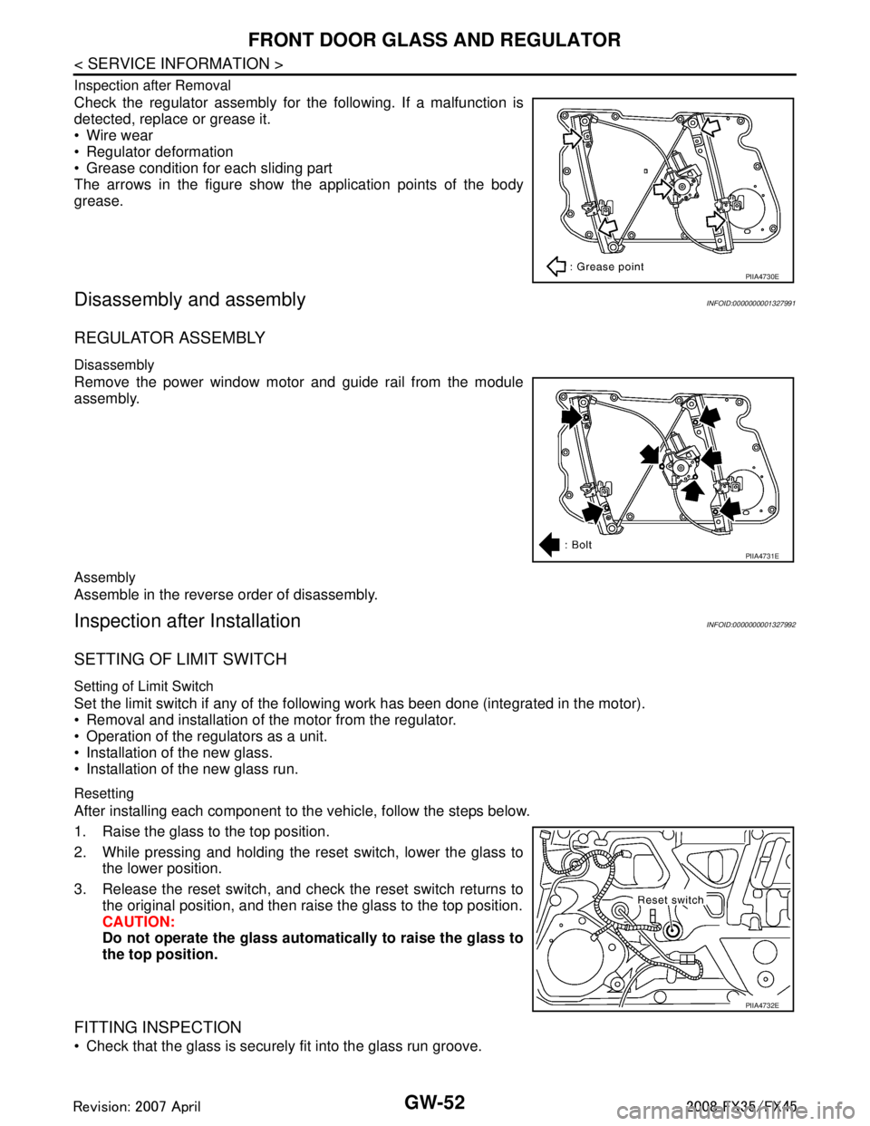
The arrows in the figure show the application points of the body
grease.
Disassembly and assemblyINFOID:0000000001327991
REGULATOR ASSEMBLY
Disassembly
Remove the power window motor and guide rail from the module
assembly.
Assembly
Assemble in the reverse order of disassembly.
Inspection after InstallationINFOID:0000000001327992
SETTING OF LIMIT SWITCH
Setting of Limit Switch
Set the limit switch if any of the following work has been done (integrated in the motor).
Removal and installation of the motor from the regulator.
Operation of the regulators as a unit.
Installation of the new glass.
Installation of the new glass run.
Resetting
After installing each component to the vehicle, follow the steps below.
1. Raise the glass to the top position.
2. While pressing and holding the reset switch, lower the glass to the lower position.
3. Release the reset switch, and check the reset switch returns to the original position, and then rais e the glass to the top position.
CAUTION:
Do not operate the glass automa tically to raise the glass to
the top position.
FITTING INSPECTION
Check that the glass is securely fit into the glass run groove.
PIIA4730E
PIIA4731E
PIIA4732E
3AA93ABC3ACD3AC03ACA3AC03AC63AC53A913A773A893A873A873A8E3A773A983AC73AC93AC03AC3
3A893A873A873A8F3A773A9D3AAF3A8A3A8C3A863A9D3AAF3A8B3A8C
Page 2971 of 3924

GW-58
< SERVICE INFORMATION >
INSIDE MIRROR
Removal and Installation
INFOID:0000000001327997
REMOVAL
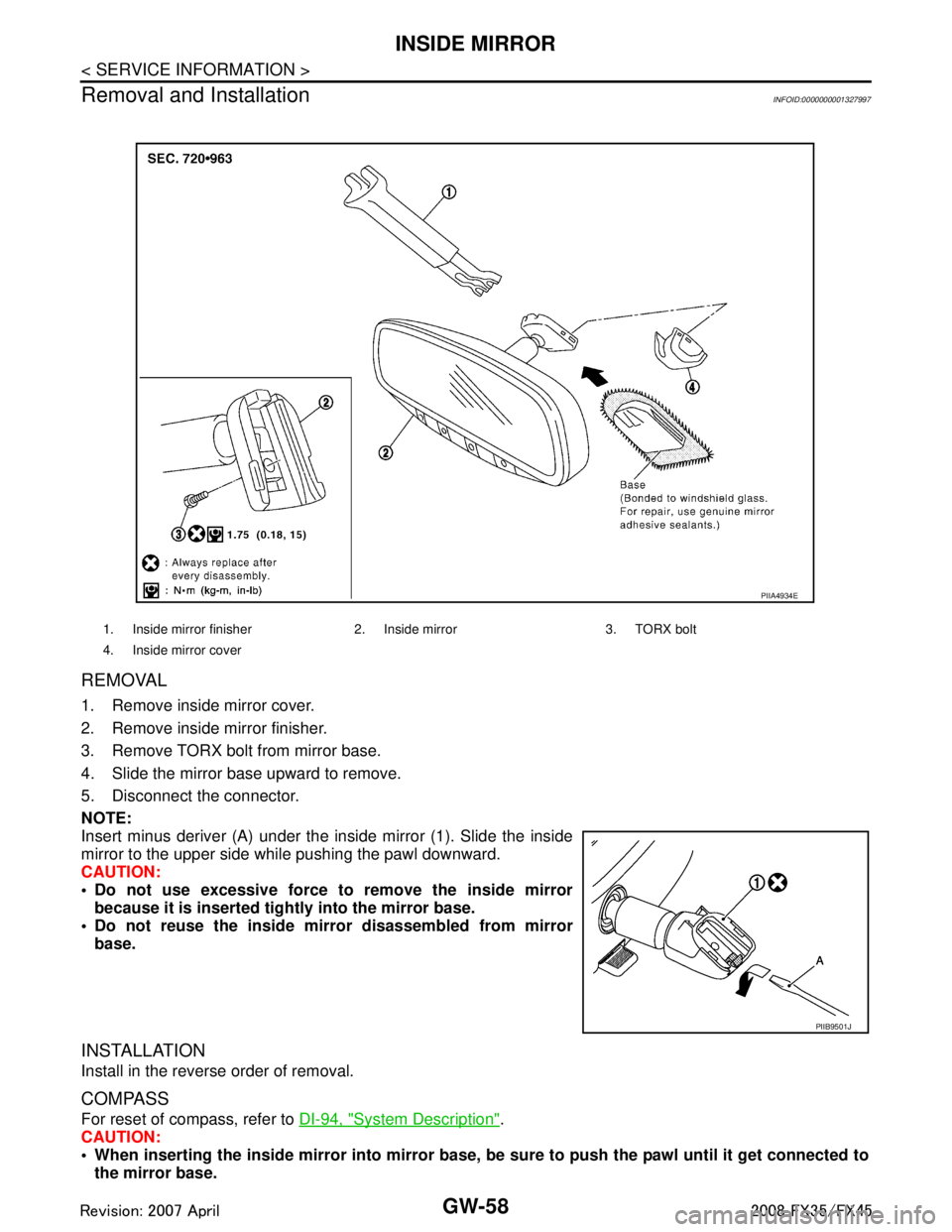
1. Remove inside mirror cover.
2. Remove inside mirror finisher.
3. Remove TORX bolt from mirror base.
4. Slide the mirror base upward to remove.
5. Disconnect the connector.
NOTE:
Insert minus deriver (A) under the inside mirror (1). Slide the inside
mirror to the upper side while pushing the pawl downward.
CAUTION:
Do not use excessive force to remove the inside mirror because it is inserted tightly into the mirror base.
Do not reuse the inside mi rror disassembled from mirror
base.
INSTALLATION
Install in the reverse order of removal.
COMPASS
For reset of compass, refer to DI-94, "System Description".
CAUTION:
When inserting the inside mirror into mirror base, be sure to push the pawl until it get connected to
the mirror base.
1. Inside mirror finisher 2. In side mirror 3. TORX bolt
4. Inside mirror cover
PIIA4934E
PIIB9501J
3AA93ABC3ACD3AC03ACA3AC03AC63AC53A913A773A893A873A873A8E3A773A983AC73AC93AC03AC3
3A893A873A873A8F3A773A9D3AAF3A8A3A8C3A863A9D3AAF3A8B3A8C
Page 3526 of 3924

SUNROOFRF-11
< SERVICE INFORMATION >
C
DE
F
G H
J
K L
M A
B
RF
N
O P
to BCM terminal 49 and 52
through body grounds M35, M45, M85 and R6.
TILT UP / SLIDE CLOSE OPERATION
When tilt up / slide close switch is pressed,
Ground is supplied
to sunroof motor assembly terminal 1
through sunroof switch terminal 3
through sunroof switch terminal 2
through body grounds M35, M45, M85 and R6.
Then, the sunroof tilt up / slide close.
TILT DOWN / SLIDE OPEN OPERATION
When tilt down / slide open switch is pressed,
Ground is supplied
to sunroof motor assembly terminal 5
through sunroof switch terminal 1
through sunroof switch terminal 2
through body grounds M35, M45, M85 and R6.
Then, the sunroof tilt down / slide open.
AUTO OPERATION
The power sunroof AUTO feature makes it possible to slide open and slide close or tilt up and tilt down the
sunroof without holding the sunroof switch in the down or up / tilt up or tilt down position.
RETAINED POWER OPERATION
When the ignition switch is turned to OFF position fr om ON position, power is supplied for 45 seconds.
through BCM terminal 53.
to sunroof motor assembly terminal 9.
When power is supplied, the sunroof can be operated.
The retained power operation is canceled when the driver or passenger side door is opened.
RAP signal period can be changed by CONSULT-III. Refer to RF-15, "
CONSULT-III Function (BCM)".
ANTI-PINCH FUNCTION
The CPU of sunroof motor monitors the sunroof motor operation and the sunroof position (fully-closed or
other) by the signals from sunroof motor.
When sunroof motor detects an interruption during the following slide close and tilt down operation, sunroof
switch controls the motor for open and the sunroof will operate until full up position (when tilt down operate) or
125 mm (4.92 in) or more in an open direction (when slide close operate).
close operation and tilt down when ignition switch is in the ON position.
close operation and tilt down during retained power operation.
MEMORY RESET PROCEDURE
1. Please observe the following instructions while confirming the sunroof operation.
NOTE:
Do not disconnect the electronic power while the sunroof is operating or within 5 seconds after the sunroof
stops. (to wipe-out the memory of lid position and operating friction.)
2. Initialization of system should be conducted after the following conditions.
When the battery is out or connector is disconnected wh ile sunroof is operating or within 5 seconds after
sunroof stops.
When the sunroof motor is changed.
When an emergency handle is used.
When the sunroof does not operate normally. (Incomplete initialization conditions)
INITIALIZATION PROCEDURE
If the sunroof does not close or open automatically, us e the following procedure to return sunroof operation to
normal.
1. Close the sunroof if it is not in the closed positi on. It may be necessary to repeatedly push the switch to
close the sunroof.
2. Press and hold the TILT UP switch. Do not release the switch, keep pressure on it. After 10 seconds of
depressing, the sunroof will tilt up, then stop. Release the button.
3AA93ABC3ACD3AC03ACA3AC03AC63AC53A913A773A893A873A873A8E3A773A983AC73AC93AC03AC3
3A893A873A873A8F3A773A9D3AAF3A8A3A8C3A863A9D3AAF3A8B3A8C
Page 3652 of 3924

AUTOMATIC DRIVE POSITIONERSE-13
< SERVICE INFORMATION >
C
DE
F
G H
J
K L
M A
B
SE
N
O P
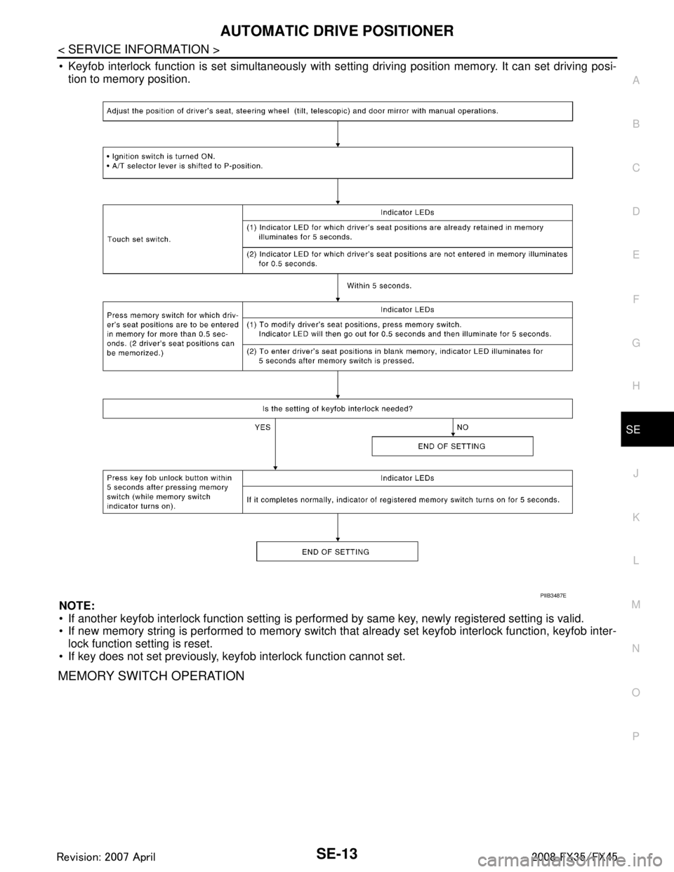
Keyfob interlock function is set simultaneously with se tting driving position memory. It can set driving posi-
tion to memory position.
NOTE:
If another keyfob interlock function setting is perform ed by same key, newly registered setting is valid.
If new memory string is performed to memory switch t hat already set keyfob interlock function, keyfob inter-
lock function setting is reset.
If key does not set previously, keyfob interlock function cannot set.
MEMORY SWITCH OPERATION
PIIB3487E
3AA93ABC3ACD3AC03ACA3AC03AC63AC53A913A773A893A873A873A8E3A773A983AC73AC93AC03AC3
3A893A873A873A8F3A773A9D3AAF3A8A3A8C3A863A9D3AAF3A8B3A8C
Page 3676 of 3924

AUTOMATIC DRIVE POSITIONERSE-37
< SERVICE INFORMATION >
C
DE
F
G H
J
K L
M A
B
SE
N
O P
Work FlowINFOID:0000000001328106
1. Check the symptom and customer's requests.
2. Understand the system description. Refer to SE-12, "
System Description".
3. Perform the preliminary check, refer to SE-37, "
Preliminary Check".
4. Perform the CAN communication inspec tion using CONSULT-III, refer to SE-40, "
CONSULT-III Function
(AUTO DRIVE POS.)".
5. Perform the self-diagnosis. Refer to SE-42, "
Check CAN Communication System".
6. Repair or replace depending on the self-diagnostic results.
7. Based on the trouble diagnosis chart, repair or replace the cause of the malfunction. Refer to SE-43,
"Symptom Chart".
8. Does the automatic drive pos itioner system operate normally?
If it is normal, GO TO 8.
If it is not normal, GO TO 3.
9. INSPECTION END
Preliminary CheckINFOID:0000000001328107
SETTING CHANGE FUNCTION
The settings of the automatic driving positioner system can be changed, using CONSULT-III and the display
unit in the center of the instrument panel.
× : Applicable –: Not applicable
It is possible to set sliding driver seat fo r entry/exit of vehicle by pressing set switch.
37 WSeat sliding switch
BACKWARD signal
InputWhen seat sliding switch
BACKWARD operation
0
Other than above Battery voltage
38 LG/B Seat reclining switch
BACKWARD signal InputWhen seat reclining switch
BACKWARD operation
0
Other than above Battery voltage
39 L/G Front lifting switch
DOWN signal InputWhen front lifting switch
DOWN operation
0
Other than above Battery voltage
40 L/Y Rear lifting switch
DOWN signal
InputWhen rear lifting switch
DOWN operation
0
Other than above Battery voltage
61E B/Y Ground (signal) — — 0 Te r -
minal Wire
Color ItemSignal Input/
Output Condition Voltage (V)
(Approx.)
Setting item Content CONSULT-III
(WORK SUPPORT) Display unitFactory
setting
Change seat sliding volume
setting The distance at retain operation can
be selected from the following 3
modes. 40 mm
—×
80 mm —
150 mm —
Change the Entry/Exit seat
slide function setting The seat sliding turnout and return
at entry/exit can be selected: ON
(operated) – OFF (not operated) ON ON: Indicator lamp ON
×
OFF OFF: Indicator lamp OFF —
Change the Entry/Exit tilt steer-
ing wheel function setting Tilt up and backward steering wheel
at entry and exit can be selected:
ON (operated) - OFF (not operated) ON ON: Indicator lamp ON
×
OFF OFF: Indicator lamp OFF —
Reset custom settings All settings to default. — Default: Setting button
OFF
—
3AA93ABC3ACD3AC03ACA3AC03AC63AC53A913A773A893A873A873A8E3A773A983AC73AC93AC03AC3
3A893A873A873A8F3A773A9D3AAF3A8A3A8C3A863A9D3AAF3A8B3A8C