seal INFINITI FX35 2008 Service Manual
[x] Cancel search | Manufacturer: INFINITI, Model Year: 2008, Model line: FX35, Model: INFINITI FX35 2008Pages: 3924, PDF Size: 81.37 MB
Page 3823 of 3924
REAR OIL SEALTF-37
< SERVICE INFORMATION >
CEF
G H
I
J
K L
M A
B
TF
N
O P
REAR OIL SEAL
Removal and InstallationINFOID:0000000001327458
REMOVAL
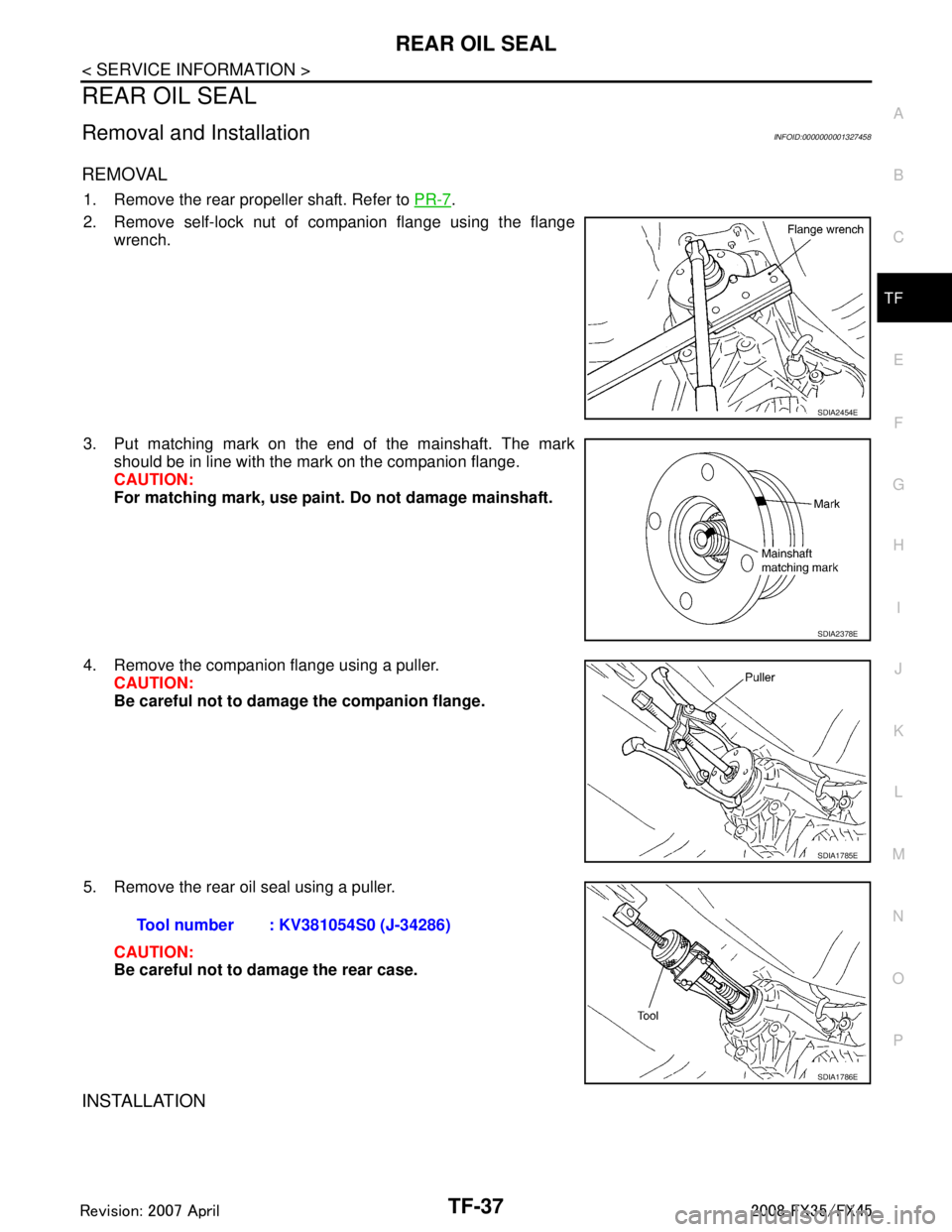
1. Remove the rear propeller shaft. Refer to PR-7.
2. Remove self-lock nut of companion flange using the flange wrench.
3. Put matching mark on the end of the mainshaft. The mark should be in line with the mark on the companion flange.
CAUTION:
For matching mark, use paint. Do not damage mainshaft.
4. Remove the companion flange using a puller. CAUTION:
Be careful not to damage the companion flange.
5. Remove the rear oil seal using a puller. CAUTION:
Be careful not to damage the rear case.
INSTALLATION
SDIA2454E
SDIA2378E
SDIA1785E
Tool number : KV381054S0 (J-34286)
SDIA1786E
3AA93ABC3ACD3AC03ACA3AC03AC63AC53A913A773A893A873A873A8E3A773A983AC73AC93AC03AC3
3A893A873A873A8F3A773A9D3AAF3A8A3A8C3A863A9D3AAF3A8B3A8C
Page 3824 of 3924
TF-38
< SERVICE INFORMATION >
REAR OIL SEAL
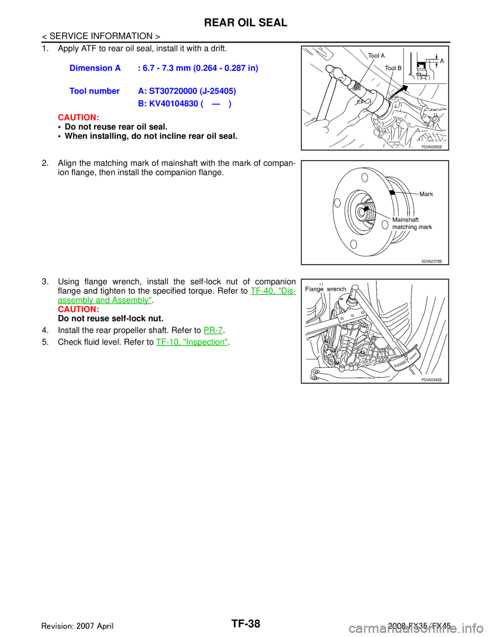
1. Apply ATF to rear oil seal, install it with a drift.CAUTION:
Do not reuse rear oil seal.
When installing, do not incline rear oil seal.
2. Align the matching mark of mainshaft with the mark of compan- ion flange, then install the companion flange.
3. Using flange wrench, install the self-lock nut of companion flange and tighten to the specified torque. Refer to TF-40, "
Dis-
assembly and Assembly".
CAUTION:
Do not reuse self-lock nut.
4. Install the rear propeller shaft. Refer to PR-7
.
5. Check fluid level. Refer to TF-10, "
Inspection".
Dimension A : 6.7 - 7.3 mm (0.264 - 0.287 in)
Tool number A: ST30720000 (J-25405)
B: KV40104830 ( — )
PDIA0292E
SDIA2378E
PDIA0245E
3AA93ABC3ACD3AC03ACA3AC03AC63AC53A913A773A893A873A873A8E3A773A983AC73AC93AC03AC3
3A893A873A873A8F3A773A9D3AAF3A8A3A8C3A863A9D3AAF3A8B3A8C
Page 3827 of 3924
TRANSFER ASSEMBLYTF-41
< SERVICE INFORMATION >
CEF
G H
I
J
K L
M A
B
TF
N
O P
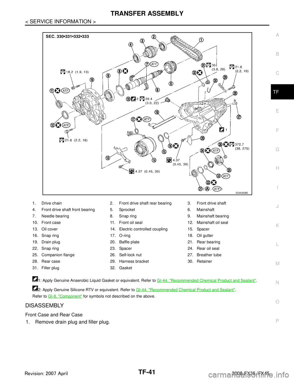
DISASSEMBLY
Front Case and Rear Case
1. Remove drain plug and filler plug.
1. Drive chain 2. Front drive shaft rear bearing 3. Front drive shaft
4. Front drive shaft front bearing 5. Sprocket 6. Mainshaft
7. Needle bearing 8. Snap ring 9. Mainshaft bearing
10. Front case 11. Front oil seal 12. Mainshaft oil seal
13. Oil cover 14. Electric controlled coupling 15. Spacer
16. Snap ring 17. O-ring 18. Oil gutter
19. Drain plug 20. Baffle plate 21. Rear bearing
22. Snap ring 23. Spacer 24. Rear oil seal
25. Companion flange 26. Self-lock nut 27. Breather tube
28. Rear case 29. Harness bracket 30. Retainer
31. Filler plug 32. Gasket 1: Apply Genuine Anaerobic Liquid Gasket or equivalent. Refer to GI-44, "
Recommended Chemical Product and Sealant".
2: Apply Genuine Silicone RTV or equivalent. Refer to GI-44, "
Recommended Chemical Product and Sealant".
Refer to GI-8, "
Component" for symbols not described on the above.
SDIA3608E
3AA93ABC3ACD3AC03ACA3AC03AC63AC53A913A773A893A873A873A8E3A773A983AC73AC93AC03AC3
3A893A873A873A8F3A773A9D3AAF3A8A3A8C3A863A9D3AAF3A8B3A8C
Page 3828 of 3924
TF-42
< SERVICE INFORMATION >
TRANSFER ASSEMBLY
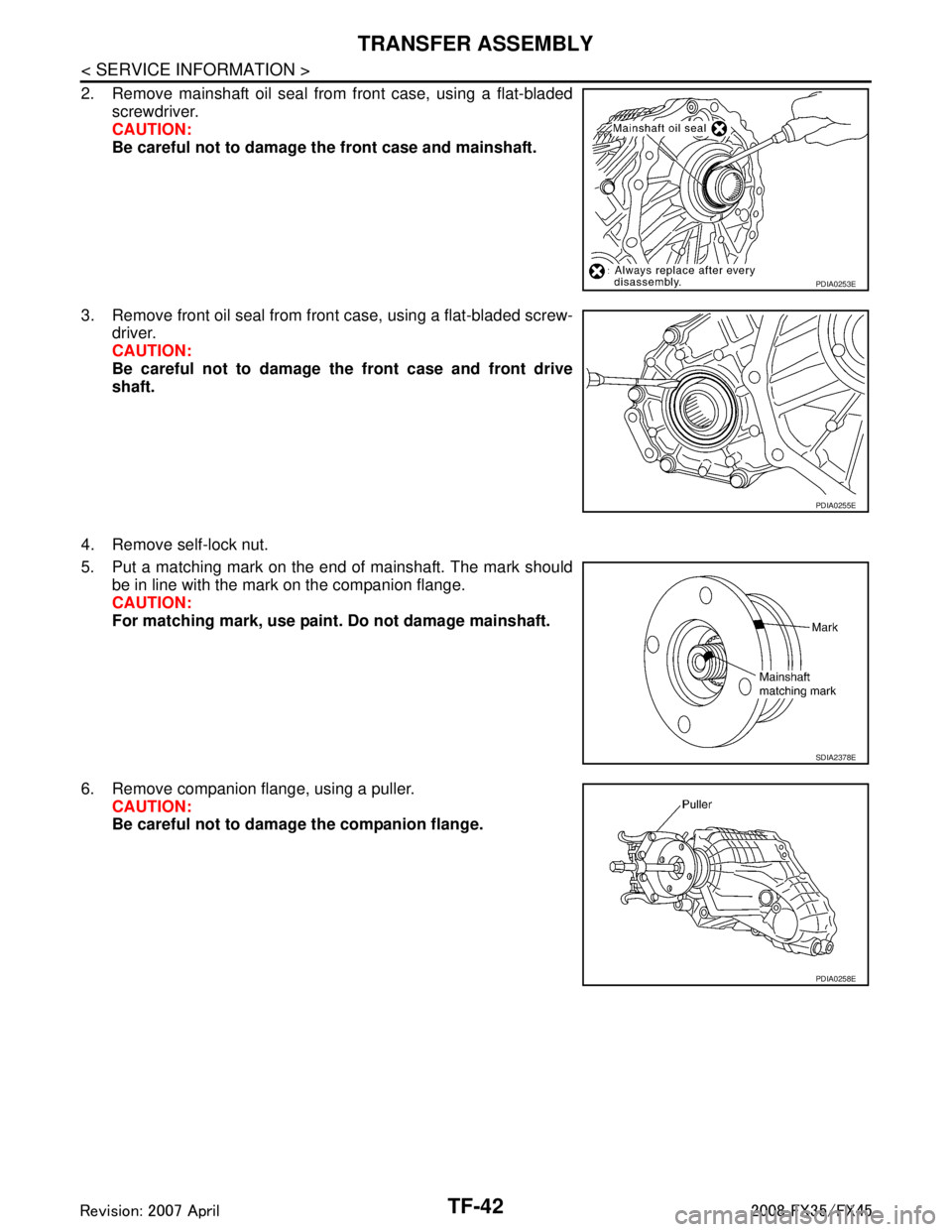
2. Remove mainshaft oil seal from front case, using a flat-bladedscrewdriver.
CAUTION:
Be careful not to damage the front case and mainshaft.
3. Remove front oil seal from front case, using a flat-bladed screw- driver.
CAUTION:
Be careful not to damage the front case and front drive
shaft.
4. Remove self-lock nut.
5. Put a matching mark on the end of mainshaft. The mark should be in line with the mark on the companion flange.
CAUTION:
For matching mark, use paint. Do not damage mainshaft.
6. Remove companion flange, using a puller. CAUTION:
Be careful not to damage the companion flange.
PDIA0253E
PDIA0255E
SDIA2378E
PDIA0258E
3AA93ABC3ACD3AC03ACA3AC03AC63AC53A913A773A893A873A873A8E3A773A983AC73AC93AC03AC3
3A893A873A873A8F3A773A9D3AAF3A8A3A8C3A863A9D3AAF3A8B3A8C
Page 3829 of 3924
TRANSFER ASSEMBLYTF-43
< SERVICE INFORMATION >
CEF
G H
I
J
K L
M A
B
TF
N
O P
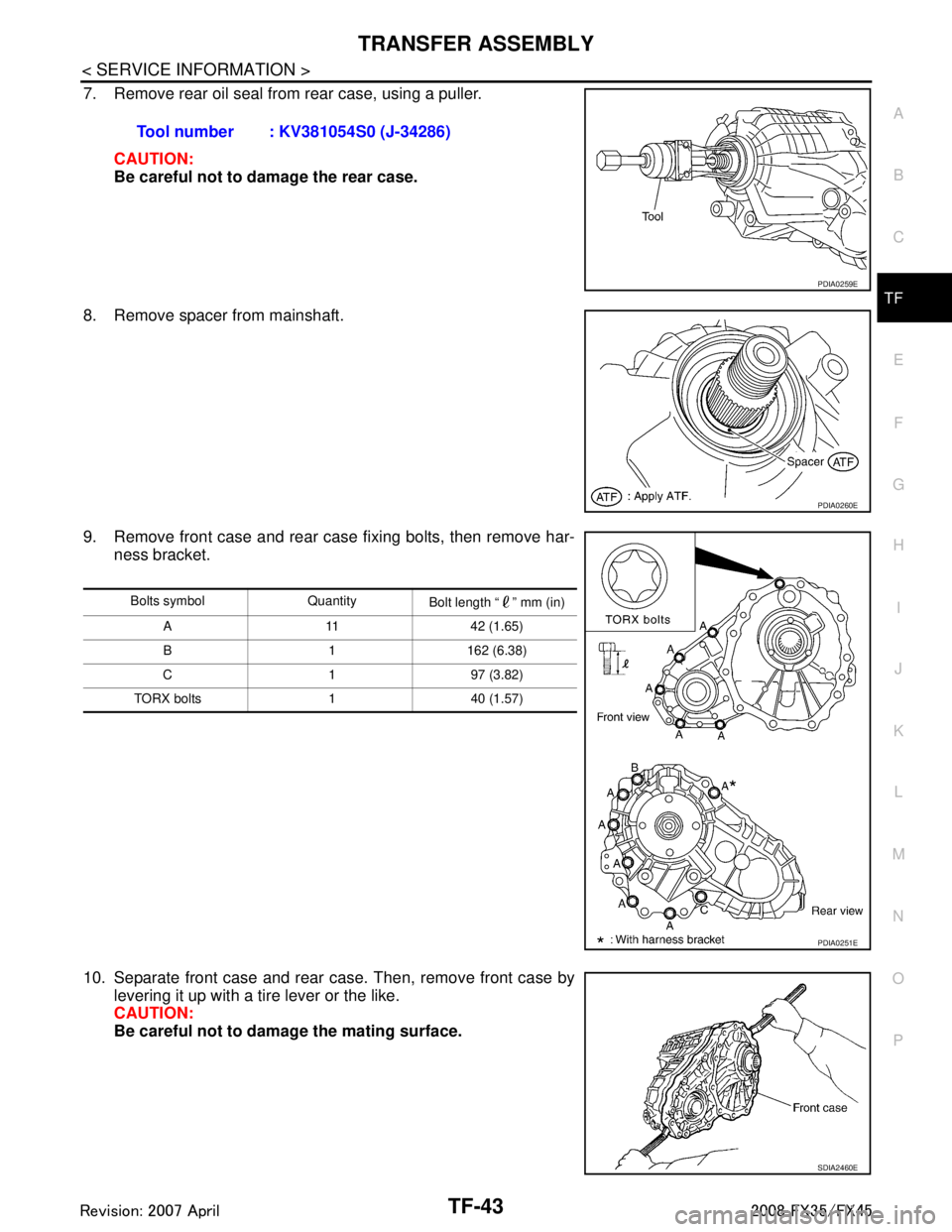
7. Remove rear oil seal from rear case, using a puller.
CAUTION:
Be careful not to damage the rear case.
8. Remove spacer from mainshaft.
9. Remove front case and rear case fixing bolts, then remove har- ness bracket.
10. Separate front case and rear case. Then, remove front case by levering it up with a tire lever or the like.
CAUTION:
Be careful not to damage the mating surface.Tool number : KV381054S0 (J-34286)
PDIA0259E
PDIA0260E
Bolts symbol Quantity
Bolt length “ ” mm (in)
A 11 42 (1.65)
B 1 162 (6.38)
C197 (3.82)
TORX bolts 1 40 (1.57)
PDIA0251E
SDIA2460E
3AA93ABC3ACD3AC03ACA3AC03AC63AC53A913A773A893A873A873A8E3A773A983AC73AC93AC03AC3
3A893A873A873A8F3A773A9D3AAF3A8A3A8C3A863A9D3AAF3A8B3A8C
Page 3837 of 3924
TRANSFER ASSEMBLYTF-51
< SERVICE INFORMATION >
CEF
G H
I
J
K L
M A
B
TF
N
O P
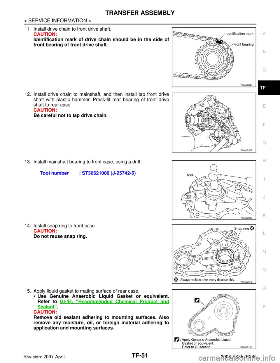
11. Install drive chain to front drive shaft. CAUTION:
Identification mark of drive ch ain should be in the side of
front bearing of front drive shaft.
12. Install drive chain to mainshaft, and then install tap front drive shaft with plastic hammer. Press-fit rear bearing of front drive
shaft to rear case.
CAUTION:
Be careful not to tap drive chain.
13. Install mainshaft bearing to front case, using a drift.
14. Install snap ring to front case. CAUTION:
Do not reuse snap ring.
15. Apply liquid gasket to mating surface of rear case. Use Genuine Anaerobic Liqu id Gasket or equivalent.
Refer to GI-44, "
Recommended Chemical Product and
Sealant".
CAUTION:
Remove old sealant adhering to mounting surfaces. Also
remove any moisture, oil, or foreign material adhering to
application and mounting surfaces.
PDIA0284E
PDIA0257E
Tool number : ST30621000 (J-25742-5)
PDIA0283E
PDIA0267E
SDIA2312E
3AA93ABC3ACD3AC03ACA3AC03AC63AC53A913A773A893A873A873A8E3A773A983AC73AC93AC03AC3
3A893A873A873A8F3A773A9D3AAF3A8A3A8C3A863A9D3AAF3A8B3A8C
Page 3838 of 3924
TF-52
< SERVICE INFORMATION >
TRANSFER ASSEMBLY
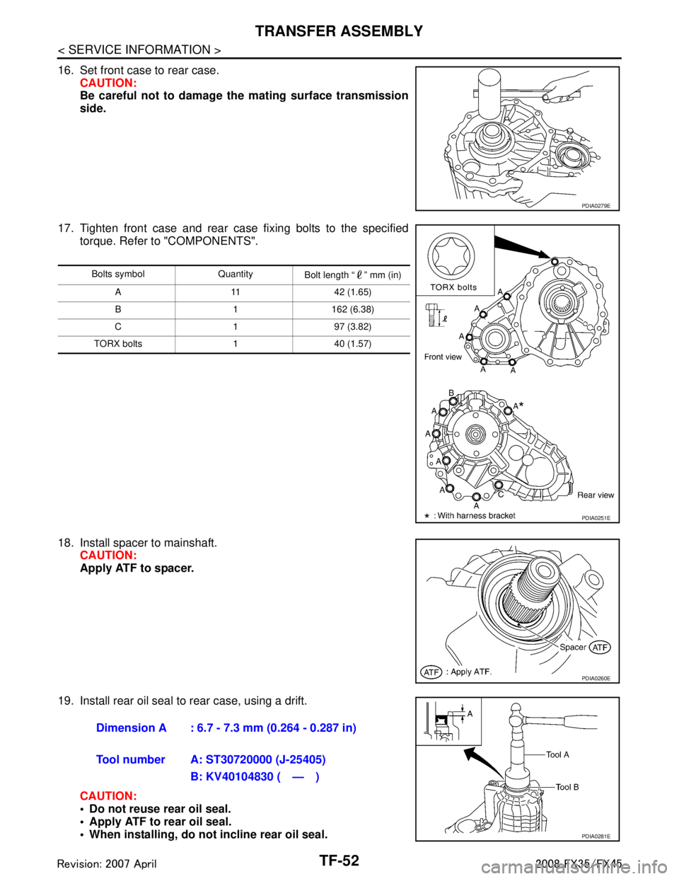
16. Set front case to rear case.CAUTION:
Be careful not to damage th e mating surface transmission
side.
17. Tighten front case and rear case fixing bolts to the specified torque. Refer to "COMPONENTS".
18. Install spacer to mainshaft. CAUTION:
Apply ATF to spacer.
19. Install rear oil seal to rear case, using a drift. CAUTION:
Do not reuse rear oil seal.
Apply ATF to rear oil seal.
When installing, do not incline rear oil seal.
PDIA0279E
Bolts symbol Quantity Bolt length “ ” mm (in)
A 11 42 (1.65)
B 1 162 (6.38)
C197 (3.82)
TORX bolts 1 40 (1.57)
PDIA0251E
PDIA0260E
Dimension A : 6.7 - 7.3 mm (0.264 - 0.287 in)
Tool number A: ST30720000 (J-25405) B: KV40104830 ( — )
PDIA0281E
3AA93ABC3ACD3AC03ACA3AC03AC63AC53A913A773A893A873A873A8E3A773A983AC73AC93AC03AC3
3A893A873A873A8F3A773A9D3AAF3A8A3A8C3A863A9D3AAF3A8B3A8C
Page 3839 of 3924
TRANSFER ASSEMBLYTF-53
< SERVICE INFORMATION >
CEF
G H
I
J
K L
M A
B
TF
N
O P
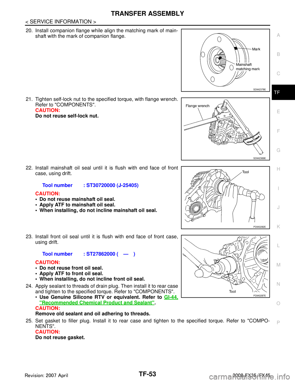
20. Install companion flange while align the matching mark of main- shaft with the mark of companion flange.
21. Tighten self-lock nut to the specified torque, with flange wrench. Refer to "COMPONENTS".
CAUTION:
Do not reuse self-lock nut.
22. Install mainshaft oil seal until it is flush with end face of front case, using drift.
CAUTION:
Do not reuse mainshaft oil seal.
Apply ATF to mainshaft oil seal.
When installing, do not in cline mainshaft oil seal.
23. Install front oil seal until it is flush with end face of front case, using drift.
CAUTION:
Do not reuse front oil seal.
Apply ATF to front oil seal.
When installing, do not incline front oil seal.
24. Apply sealant to threads of drain plug. Then install it to rear case and tighten to the specified torque. Refer to "COMPONENTS".
Use Genuine Silicone RTV or equivalent. Refer to GI-44,
"Recommended Chemical Product and Sealant".
CAUTION:
Remove old sealant and oil adhering to threads.
25. Set gasket to filler plug. Install it to rear case and tighten to the specified torque. Refer to "COMPO-
NENTS".
CAUTION:
Do not reuse gasket.
SDIA2378E
SDIA2369E
Tool number : ST30720000 (J-25405)
PDIA0282E
Tool number : ST27862000 ( — )
PDIA0287E
3AA93ABC3ACD3AC03ACA3AC03AC63AC53A913A773A893A873A873A8E3A773A983AC73AC93AC03AC3
3A893A873A873A8F3A773A9D3AAF3A8A3A8C3A863A9D3AAF3A8B3A8C
Page 3844 of 3924
WT-4
< SERVICE INFORMATION >
PRECAUTIONS
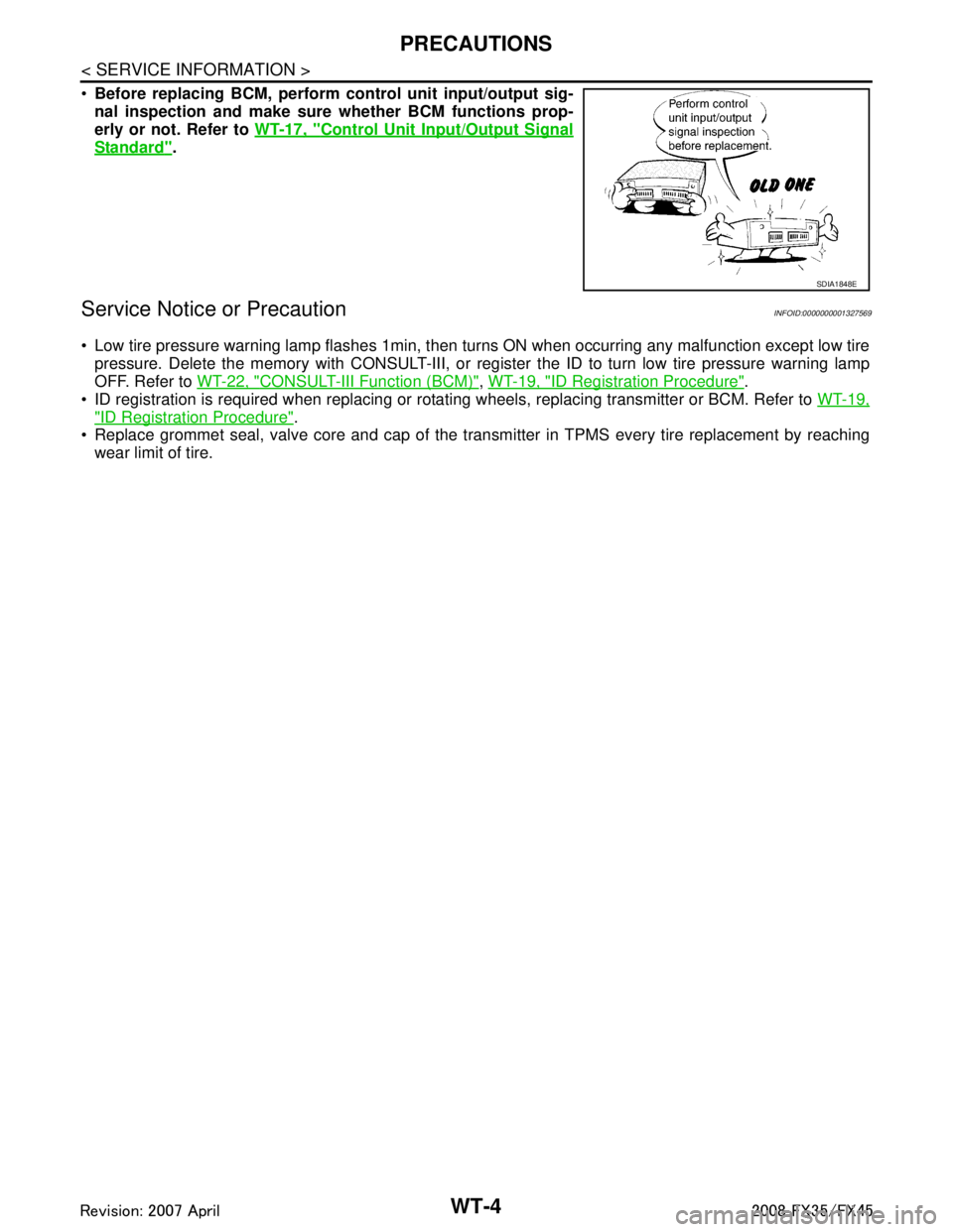
Before replacing BCM, perform c ontrol unit input/output sig-
nal inspection and make sure whether BCM functions prop-
erly or not. Refer to WT-17, "
Control Unit Input/Output Signal
Standard".
Service Notice or PrecautionINFOID:0000000001327569
Low tire pressure warning lamp flashes 1min, then turns ON when occurring any malfunction except low tire
pressure. Delete the memory with CONSULT-III, or regi ster the ID to turn low tire pressure warning lamp
OFF. Refer to WT-22, "
CONSULT-III Function (BCM)", WT-19, "ID Registration Procedure".
ID registration is required when replacing or rotati ng wheels, replacing transmitter or BCM. Refer to WT-19,
"ID Registration Procedure".
Replace grommet seal, valve core and cap of the transmi tter in TPMS every tire replacement by reaching
wear limit of tire.
SDIA1848E
3AA93ABC3ACD3AC03ACA3AC03AC63AC53A913A773A893A873A873A8E3A773A983AC73AC93AC03AC3
3A893A873A873A8F3A773A9D3AAF3A8A3A8C3A863A9D3AAF3A8B3A8C