air condition INFINITI FX35 2008 Workshop Manual
[x] Cancel search | Manufacturer: INFINITI, Model Year: 2008, Model line: FX35, Model: INFINITI FX35 2008Pages: 3924, PDF Size: 81.37 MB
Page 231 of 3924

AT-158
< SERVICE INFORMATION >
DTC P1815 MANUAL MODE SWITCH
Diagnosis Procedure
INFOID:0000000001327325
1.CHECK CAN COMMUNICATION LINE
Perform the self-diagnosis.
Is a malfunction in the CAN communication indicated in the results?
YES >> Check CAN communication line. Refer to AT- 9 4.
NO >> GO TO 2.
2.CHECK MANUAL MODE SWITCH CIRCUIT
With CONSULT-III
1. Turn ignition switch ON.
2. Select “ECU INPUT SIGNALS” in “DATA MONI TOR” mode for “TRANSMISSION” with CONSULT-III.
3. Read out ON/OFF switching action of “MANU MO DE SW”, “NON M-MODE SW”, “UP SW LEVER”,
“DOWN SW LEVER”.
Without CONSULT-III
Drive vehicle in the manual mode, and confirm that the actual gear position and the meter's indication of the
position mutually coincide when the selector lever is shifted to the “+ (up)” or “- (down)” side (1st ⇔ 5th gear).
OK or NG
OK >> GO TO 4.
NG >> GO TO 3.
3.DETECT MALFUNCTIONING ITEM
Check the following.
Manual mode switch. Refer to AT-159, "Component Inspection".
Pin terminals for damage or loose connection with harness connector.
Open circuit or short to ground or short to power in harness or connector for A/T device (manual mode
switch).
Unified meter and A/C amp. Refer to DI-5
.
OK or NG
OK >> GO TO 4.
NG >> Repair or replace damaged parts.
4.CHECK DTC
Perform AT-155, "
DTC Confirmation Procedure".
OK or NG
OK >> INSPECTION END
NG >> GO TO 5.
9 GY Starter relay Selector lever in “N” and “P
” positions. Battery voltage
Selector lever in other positions. 0 V
Te r m i n a l
Wire
color Item Condition Data (Approx.)
Item name Condition Display Value
MANU MODE SW Manual shift gate position (neutral) ON
Other than the above OFF
NON M-MODE SW Manual shift gate position OFF
Other than the above ON
UP SW LEVER selector lever: +side ON
Other than the above OFF
DOWN SW LEVER selector lever: -side ON
Other than the above OFF
3AA93ABC3ACD3AC03ACA3AC03AC63AC53A913A773A893A873A873A8E3A773A983AC73AC93AC03AC3
3A893A873A873A8F3A773A9D3AAF3A8A3A8C3A863A9D3AAF3A8B3A8C
Page 237 of 3924

AT-164
< SERVICE INFORMATION >
CLOSED THROTTLE POSITION AND WIDE OPEN THROTTLE POSITION CIR-
CUIT
CLOSED THROTTLE POSITION AND WIDE OPEN THROTTLE POSITION
CIRCUIT
CONSULT-III Reference Value in Data Monitor ModeINFOID:0000000001327353
Diagnosis ProcedureINFOID:0000000001327354
1.CHECK CAN COMMUNICATION LINE
With CONSULT-III
Perform the self-diagnosis.
Without CONSULT-III
Perform the self-diagnosis. Refer to AT-91, "
Diagnosis Procedure without CONSULT-III".
Is a malfunction in the CAN communication indicated in the results?
YES >> Check CAN communication line. Refer to AT- 9 4.
NO >> GO TO 2.
2.CHECK THROTTLE POSI TION SIGNAL CIRCUIT
With CONSULT-III
1. Turn ignition switch ON.
2. Select “ECU INPUT SIGNALS” in “DATA MONI TOR” mode for “TRANSMISSION” with CONSULT-III.
3. Depress accelerator pedal and read out the value of “CLSD THL POS” and “W/O THL POS”.
OK or NG
OK >> INSPECTION END
NG >> Check the following items. If NG, repair or replace damaged parts.
Perform the self-diagnosis for “ENG INE” with CONSULT-III. Refer to EC-117, "
CONSULT-III
Function (ENGINE)"(for VQ35DE) or EC-695, "CONSULT-III Function (ENGINE)"(for VK45DE).
Open circuit or short to ground or shor t to power in harness or connectors.
Pin terminals for damage or loos e connection with harness connector.
Item name Condition Display value
CLSD THL POS Released accelerator pedal. ON
Fully depressed accelerator pedal. OFF
W/O THL POS Fully depressed accelerator pedal. ON
Released accelerator pedal. OFF
Accelerator Pedal Operation Monitor Item
CLSD THL POS W/O THL POS
Released ON OFF
Fully depressed OFF ON
3AA93ABC3ACD3AC03ACA3AC03AC63AC53A913A773A893A873A873A8E3A773A983AC73AC93AC03AC3
3A893A873A873A8F3A773A9D3AAF3A8A3A8C3A863A9D3AAF3A8B3A8C
Page 238 of 3924

BRAKE SIGNAL CIRCUITAT-165
< SERVICE INFORMATION >
DE
F
G H
I
J
K L
M A
B
AT
N
O P
BRAKE SIGNAL CIRCUIT
CONSULT-III Reference Val ue in Data Monitor ModeINFOID:0000000001327355
Diagnosis ProcedureINFOID:0000000001327356
1.CHECK CAN COMMUNICATION LINE
With CONSULT-III
Perform the self-diagnosis.
Without CONSULT-III
Perform the self-diagnosis. Refer to AT-91, "
Diagnosis Procedure without CONSULT-III".
Is a malfunction in the CAN communication indicated in the results?
YES >> Check CAN communication line. Refer to AT- 9 4.
NO >> GO TO 2.
2.CHECK STOP LAMP SWITCH CIRCUIT
With CONSULT-III
1. Turn ignition switch ON.
2. Select “ECU INPUT SIGNALS” in “DATA MONITO R” mode for “TRANSMISSION” with CONSULT-III.
3. Read out ON/OFF switching action of the “BRAKE SW”.
OK or NG
OK >> INSPECTION END
NG >> GO TO 3.
3.CHECK STOP LAMP SWITCH
Check continuity between stop lamp switch harness connector E210
terminals 1 and 2. Refer to AT-167, "
Wiring Diagram - AT - NON-
DTC".
Check stop lamp switch after adjusting brake pedal — refer to
BR-5
.
OK or NG
OK >> Check the following items. If NG, repair or replace damaged parts. Harness for short or open between battery and stop lamp switch.
Harness for short or open between stop lamp switch and unified meter and A/C amp.
NG >> Repair or replace the stop lamp switch.
Item name Condition Display value
BRAKE SW Depressed brake pedal. ON
Released brake pedal. OFF
Item name Condition Display value
BRAKE SWDepressed brake pedal. ON
Released brake pedal. OFF
Condition Continuity
When brake pedal is depressed Yes When brake pedal is released No
SCIA2144E
3AA93ABC3ACD3AC03ACA3AC03AC63AC53A913A773A893A873A873A8E3A773A983AC73AC93AC03AC3
3A893A873A873A8F3A773A9D3AAF3A8A3A8C3A863A9D3AAF3A8B3A8C
Page 243 of 3924
AT-170
< SERVICE INFORMATION >
TROUBLE DIAGNOSIS FOR SYMPTOMS
A/T Check Indicator Lamp Does Not Come On
INFOID:0000000001327361
SYMPTOM:
A/T CHECK indicator lamp does not come on for ab out 2 seconds when turning ignition switch to
“ON”.
DIAGNOSTIC PROCEDURE
1.CHECK CAN COMMUNICATION LINE
With CONSULT-III
Perform self-diagnosis.
Without CONSULT-III
Perform self-diagnosis. Refer to AT-91, "
Diagnosis Procedure without CONSULT-III".
Is a malfunction in the CAN communication indicated in the results?
YES >> Check CAN communication line. Refer to AT- 9 4.
NO >> GO TO 2.
2.CHECK A/T CHECK INDICATOR LAMP CIRCUIT
Check the combination meter. Refer to DI-5
.
OK or NG
OK >> GO TO 3
NG >> Repair or replace damaged parts.
3.CHECK TCM POWER SUPPLY AND GROUND CIRCUIT
Check TCM power supply and ground circuit. Refer to AT-160
.
OK or NG
OK >> INSPECTION END
NG >> Repair or replace damaged parts.
Engine Cannot Be Started in "P" or "N" PositionINFOID:0000000001327362
SYMPTOM:
Engine cannot be started with select or lever in “P” or “N” position.
Engine can be started with selector lever in “D”or “R” position.
DIAGNOSTIC PROCEDURE
1.CHECK PNP SWITCH CIRCUIT
With CONSULT-III
Perform self-diagnosis.
Without CONSULT-III
Perform self-diagnosis. Refer to AT-91, "
Diagnosis Procedure without CONSULT-III".
Do the self-diagnosis results indicate PNP switch?
YES >> Check the malfunctioning system. Refer to AT-102.
NO >> GO TO 2.
2.CHECK A/T POSITION
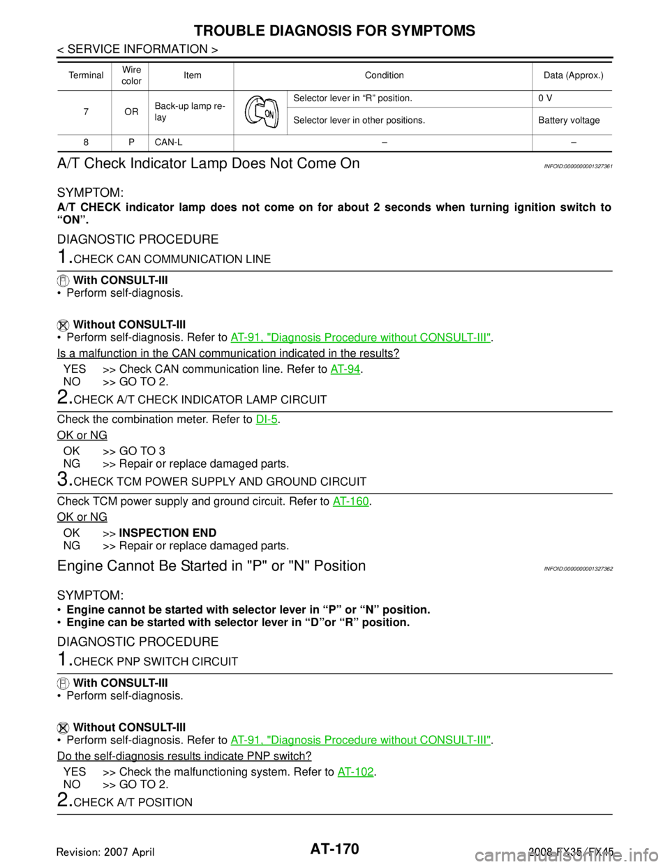
7OR Back-up lamp re-
lay Selector lever in “R” position. 0 V
Selector lever in other positions. Battery voltage
8 P CAN-L – –
Te r m i n a l
Wire
color Item Condition Data (Approx.)
3AA93ABC3ACD3AC03ACA3AC03AC63AC53A913A773A893A873A873A8E3A773A983AC73AC93AC03AC3
3A893A873A873A8F3A773A9D3AAF3A8A3A8C3A863A9D3AAF3A8B3A8C
Page 244 of 3924

TROUBLE DIAGNOSIS FOR SYMPTOMSAT-171
< SERVICE INFORMATION >
DE
F
G H
I
J
K L
M A
B
AT
N
O P
Check the A/T position. Refer to AT-207, "Checking of A/T Position".
OK or NG
OK >> GO TO 3.
NG >> Adjust A/T position. Refer to AT-207, "
Adjustment of A/T
Position".
3.CHECK STARTING SYSTEM
Check starting system. Refer to SC-8
.
OK or NG
OK >> INSPECTION END
NG >> Repair or replace damaged parts.
In "P" Position, Vehicle Moves When PushedINFOID:0000000001327363
SYMPTOM:
Even though the selector lever is set in the “P” position, the parking mechanism is not actuated,
allowing the vehicle to be moved when it is pushed.
DIAGNOSTIC PROCEDURE
1.CHECK A/T POSITION
Check the A/T position. Refer to AT-207, "
Checking of A/T Position".
OK or NG
OK >> GO TO 2.
NG >> Adjust A/T position. Refer to AT-207, "
Adjustment of A/T
Position".
2.CHECK PARKING COMPONENTS
Check parking components. Refer to AT-226, "
Parking Component (2WD Models Only)" (2WD models) or AT-
267, "Disassembly" (AWD models).
OK or NG
OK >> GO TO 3.
NG >> Repair or replace damaged parts.
3.CHECK A/T FLUID CONDITION
1. Remove oil pan. Refer to AT-215, "
Control Valve with TCM and A/T Fluid Temperature Sensor 2".
2. Check A/T fluid condition. Refer to AT-49, "
Inspections Before
Trouble Diagnosis".
OK or NG
OK >> INSPECTION END
NG >> Check the malfunction items. If any items are damaged, repair or replace damaged parts. Refer to AT-59, "
Symp-
tom Chart" (Symptom No.65).
SCIA2119E
SCIA2119E
SCIA5199E
3AA93ABC3ACD3AC03ACA3AC03AC63AC53A913A773A893A873A873A8E3A773A983AC73AC93AC03AC3
3A893A873A873A8F3A773A9D3AAF3A8A3A8C3A863A9D3AAF3A8B3A8C
Page 245 of 3924

AT-172
< SERVICE INFORMATION >
TROUBLE DIAGNOSIS FOR SYMPTOMS
In "N" Position, Vehicle Moves
INFOID:0000000001327364
SYMPTOM:
Vehicle moves forward or backwar d when selecting “N” position.
DIAGNOSTIC PROCEDURE
1.CHECK PNP SWITCH CIRCUIT
With CONSULT-III
Perform self-diagnosis.
Without CONSULT-III
Perform self-diagnosis. Refer to AT-91, "
Diagnosis Procedure without CONSULT-III".
Do the self-diagnostic results indicate PNP switch?
YES >> Check the malfunctioning system. Refer to AT-102.
NO >> GO TO 2.
2.CHECK A/T POSITION
Check the A/T position. Refer to AT-207, "
Checking of A/T Position".
OK or NG
OK >> GO TO 3.
NG >> Adjust A/T position. Refer to AT-207, "
Adjustment of A/T
Position".
3.CHECK A/T FLUID LEVEL
Check A/T fluid level. Refer to AT- 11 , "
Checking A/T Fluid".
OK or NG
OK >> GO TO 4.
NG >> Refill ATF.
4.CHECK A/T FLUID CONDITION
1. Remove oil pan. Refer to AT-215, "
Control Valve with TCM and A/T Fluid Temperature Sensor 2".
2. Check A/T fluid condition. Refer to AT-49, "
Inspections Before
Trouble Diagnosis".
OK or NG
OK >> GO TO 5.
NG >> Check the malfunction items. If any items are damaged, repair or replace damaged parts. Refer to AT-59, "
Symp-
tom Chart" (Symptom No.67).
5.CHECK SYMPTOM
Check again. Refer to “CHECK AT IDLE”.
SCIA2119E
SAT638A
SCIA5199E
3AA93ABC3ACD3AC03ACA3AC03AC63AC53A913A773A893A873A873A8E3A773A983AC73AC93AC03AC3
3A893A873A873A8F3A773A9D3AAF3A8A3A8C3A863A9D3AAF3A8B3A8C
Page 247 of 3924

AT-174
< SERVICE INFORMATION >
TROUBLE DIAGNOSIS FOR SYMPTOMS
Check the A/T fluid level. Refer to AT- 11 , "Checking A/T Fluid".
OK or NG
OK >> GO TO 5.
NG >> Refill ATF.
5.CHECK LINE PRESSURE
Check line pressure at idle with selector lever in “D” position. Refer
to AT-49, "
Inspections Before Trouble Diagnosis".
OK or NG
OK >> GO TO 8.
NG-1 >> Line pressure high: GO TO 6.
NG-2 >> Line pressure low: GO TO 7.
6.DETECT MALFUNCTIONING ITEM
1. Check control valve with TCM. Refer to AT-215, "
Control Valve with TCM and A/T Fluid Temperature Sen-
sor 2".
2. Disassemble A/T. Refer to AT-267
.
3. Check the following.
- Oil pump assembly. Refer to AT-285, "
Oil Pump".
OK or NG
OK >> GO TO 8.
NG >> Repair or replace damaged parts.
7.DETECT MALFUNCTIONING ITEM
1. Check control valve with TCM. Refer to AT-215, "
Control Valve with TCM and A/T Fluid Temperature Sen-
sor 2".
2. Disassemble A/T. Refer to AT-267
.
3. Check the following.
- Oil pump assembly. Refer to AT-285, "
Oil Pump".
- Power train system. Refer to AT-267
.
- Transmission case. Refer to AT-267
.
OK or NG
OK >> GO TO 8.
NG >> Repair or replace damaged parts.
8.CHECK A/T FLUID CONDITION
1. Remove oil pan. Refer to AT-215, "
Control Valve with TCM and A/T Fluid Temperature Sensor 2".
SAT638A
SAT494G
3AA93ABC3ACD3AC03ACA3AC03AC63AC53A913A773A893A873A873A8E3A773A983AC73AC93AC03AC3
3A893A873A873A8F3A773A9D3AAF3A8A3A8C3A863A9D3AAF3A8B3A8C
Page 248 of 3924
TROUBLE DIAGNOSIS FOR SYMPTOMSAT-175
< SERVICE INFORMATION >
DE
F
G H
I
J
K L
M A
B
AT
N
O P
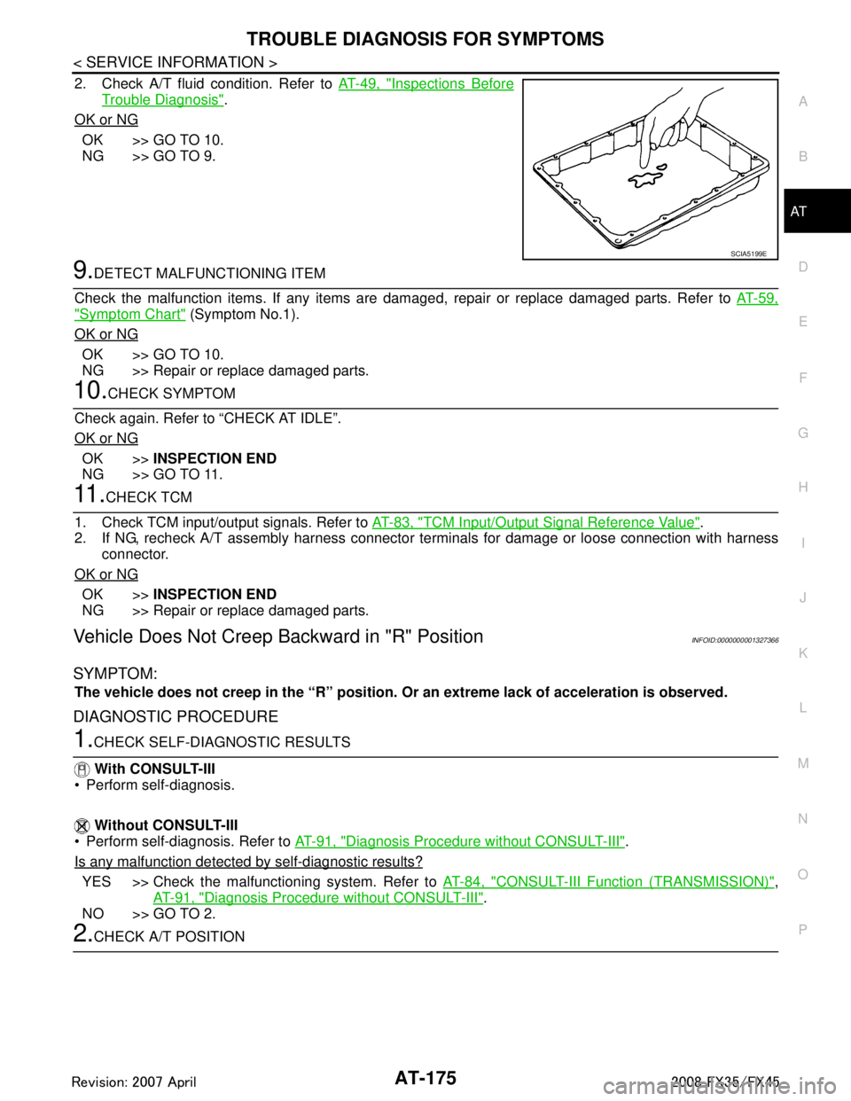
2. Check A/T fluid condition. Refer to AT-49, "Inspections Before
Trouble Diagnosis".
OK or NG
OK >> GO TO 10.
NG >> GO TO 9.
9.DETECT MALFUNCTIONING ITEM
Check the malfunction items. If any items are dam aged, repair or replace damaged parts. Refer to AT-59,
"Symptom Chart" (Symptom No.1).
OK or NG
OK >> GO TO 10.
NG >> Repair or replace damaged parts.
10.CHECK SYMPTOM
Check again. Refer to “CHECK AT IDLE”.
OK or NG
OK >> INSPECTION END
NG >> GO TO 11.
11 .CHECK TCM
1. Check TCM input/output signals. Refer to AT-83, "
TCM Input/Output Signal Reference Value".
2. If NG, recheck A/T assembly harness connector terminals for damage or loose connection with harness
connector.
OK or NG
OK >> INSPECTION END
NG >> Repair or replace damaged parts.
Vehicle Does Not Creep Backward in "R" PositionINFOID:0000000001327366
SYMPTOM:
The vehicle does not creep in the “R” position. Or an extreme lack of acceleration is observed.
DIAGNOSTIC PROCEDURE
1.CHECK SELF-DIAGNOSTIC RESULTS
With CONSULT-III
Perform self-diagnosis.
Without CONSULT-III
Perform self-diagnosis. Refer to AT-91, "
Diagnosis Procedure without CONSULT-III".
Is any malfunction detected by self-diagnostic results?
YES >> Check the malfuncti oning system. Refer to AT-84, "CONSULT-III Function (TRANSMISSION)",
AT-91, "
Diagnosis Procedure without CONSULT-III".
NO >> GO TO 2.
2.CHECK A/T POSITION
SCIA5199E
3AA93ABC3ACD3AC03ACA3AC03AC63AC53A913A773A893A873A873A8E3A773A983AC73AC93AC03AC3
3A893A873A873A8F3A773A9D3AAF3A8A3A8C3A863A9D3AAF3A8B3A8C
Page 250 of 3924

TROUBLE DIAGNOSIS FOR SYMPTOMSAT-177
< SERVICE INFORMATION >
DE
F
G H
I
J
K L
M A
B
AT
N
O P
7.DETECT MALFUNCTIONING ITEM
1. Check control valve with TCM. Refer to AT-215, "
Control Valve with TCM and A/T Fluid Temperature Sen-
sor 2".
2. Disassemble A/T. Refer to AT-267
.
3. Check the following.
- Oil pump assembly. Refer to AT-285, "
Oil Pump".
OK or NG
OK >> GO TO 9.
NG >> Repair or replace damaged parts.
8.DETECT MALFUNCTIONING ITEM
1. Check control valve with TCM. Refer to AT-215, "
Control Valve with TCM and A/T Fluid Temperature Sen-
sor 2".
2. Disassemble A/T. Refer to AT-267
.
3. Check the following.
- Oil pump assembly. Refer to AT-285, "
Oil Pump".
- Power train system. Refer to AT-267
.
- Transmission case. Refer to AT-267
.
OK or NG
OK >> GO TO 9.
NG >> Repair or replace damaged parts.
9.CHECK A/T FLUID CONDITION
1. Remove oil pan. Refer to AT-215, "
Control Valve with TCM and A/T Fluid Temperature Sensor 2".
2. Check A/T fluid condition. Refer to AT-49, "
Inspections Before
Trouble Diagnosis".
OK or NG
OK >> GO TO 10.
NG >> GO TO 13.
10.DETECT MALFUNCTIONING ITEM
Check the malfunction items. If any items are dam aged, repair or replace damaged parts. Refer to AT-59,
"Symptom Chart" (Symptom No.43).
OK or NG
OK >> GO TO 11.
NG >> Repair or replace damaged parts.
11 .CHECK SYMPTOM
Check again. Refer to “CHECK AT IDLE”.
OK or NG
OK >> INSPECTION END
NG >> GO TO 12.
12.CHECK TCM
1. Check TCM input/output signals. Refer to AT-83, "
TCM Input/Output Signal Reference Value".
2. If NG, recheck A/T assembly harness connector terminals for damage or loose connection with harness
connector.
OK or NG
OK >> INSPECTION END
NG >> Repair or replace damaged parts.
SCIA5199E
3AA93ABC3ACD3AC03ACA3AC03AC63AC53A913A773A893A873A873A8E3A773A983AC73AC93AC03AC3
3A893A873A873A8F3A773A9D3AAF3A8A3A8C3A863A9D3AAF3A8B3A8C
Page 252 of 3924

TROUBLE DIAGNOSIS FOR SYMPTOMSAT-179
< SERVICE INFORMATION >
DE
F
G H
I
J
K L
M A
B
AT
N
O P
Check stall revolution with selector lever in “D” position. Refer to AT-
49, "Inspections Before Trouble Diagnosis".
OK or NG
OK >> GO TO 5.
NG >> GO TO 7.
5.CHECK LINE PRESSURE
Check line pressure at idle with selector lever in “D” position. Refer
to AT-49, "
Inspections Before Trouble Diagnosis".
OK or NG
OK >> GO TO 8.
NG-1 >> Line pressure high: GO TO 6.
NG-2 >> Line pressure low: GO TO 7.
6.DETECT MALFUNCTIONING ITEM
1. Check control valve with TCM. Refer to AT-215, "
Control Valve with TCM and A/T Fluid Temperature Sen-
sor 2".
2. Disassemble A/T. Refer to AT-267
.
3. Check the following.
- Oil pump assembly. Refer to AT-285, "
Oil Pump".
OK or NG
OK >> GO TO 8.
NG >> Repair or replace damaged parts.
7.DETECT MALFUNCTIONING ITEM
1. Check control valve with TCM. Refer to AT-215, "
Control Valve with TCM and A/T Fluid Temperature Sen-
sor 2".
2. Disassemble A/T. Refer to AT-267
.
3. Check the following.
- Oil pump assembly. Refer to AT-285, "
Oil Pump".
- Power train system. Refer to AT-267
.
- Transmission case. Refer to AT-267
.
OK or NG
OK >> GO TO 8.
NG >> Repair or replace damaged parts.
8.CHECK A/T FLUID CONDITION
1. Remove oil pan. Refer to AT-215, "
Control Valve with TCM and A/T Fluid Temperature Sensor 2".
SAT493G
SAT494G
3AA93ABC3ACD3AC03ACA3AC03AC63AC53A913A773A893A873A873A8E3A773A983AC73AC93AC03AC3
3A893A873A873A8F3A773A9D3AAF3A8A3A8C3A863A9D3AAF3A8B3A8C