tire pressure INFINITI FX35 2008 Repair Manual
[x] Cancel search | Manufacturer: INFINITI, Model Year: 2008, Model line: FX35, Model: INFINITI FX35 2008Pages: 3924, PDF Size: 81.37 MB
Page 3870 of 3924

WT-30
< SERVICE INFORMATION >
TROUBLE DIAGNOSIS FOR SYMPTOMS
TROUBLE DIAGNOSIS FOR SYMPTOMS
Low Tire Pressure Warning Lamp Does Not Come On When Ignition Switch Is Turned
On
INFOID:0000000001327593
DIAGNOSTIC PROCEDURE
1.CHECK SELF-DIAGNOSIS RESULTS
1. Select “SELF-DIAG RESULTS” on “SELECT DIAG MODE” screen.
2. Check display contents in self-diagnostic results.
Is
“CAN COMM CIRCUIT” displayed in the self-diagnosis display items?
YES >> Malfunction in CAN communication system. Go to LAN-43, "CAN System Specification Chart".
NO >> No malfunction. GO TO 2.
2.CHECK COMBINATION METER
Check combination meter function.
OK or NG
OK >> GO TO 3.
NG >> Check combination meter. Refer to DI-5, "
System Description".
3.CHECK LOW TIRE PRESSURE WARNING LAMP
Disconnect BCM harness connectors M3 and M4.
Does the warning lamp activate?
YES >> Replace BCM. Refer to BCS-13, "Removal and Installation of BCM".
NO >> Check combination meter and repair or replace.
Low Tire Pressure Warning Lamp Stays On When Ignition Switch Is Turned On
INFOID:0000000001327594
DIAGNOSTIC PROCEDURE
1.CHECK CONNECTOR
1. Disconnect BCM harness connectors M3 and M4.
2. Check terminals for damage or loose connections.
OK or NG
OK >> GO TO 2.
NG >> Repair or replace damaged parts.
2.CHECK POWER SUPPLY CIRCUIT (BATTERY)
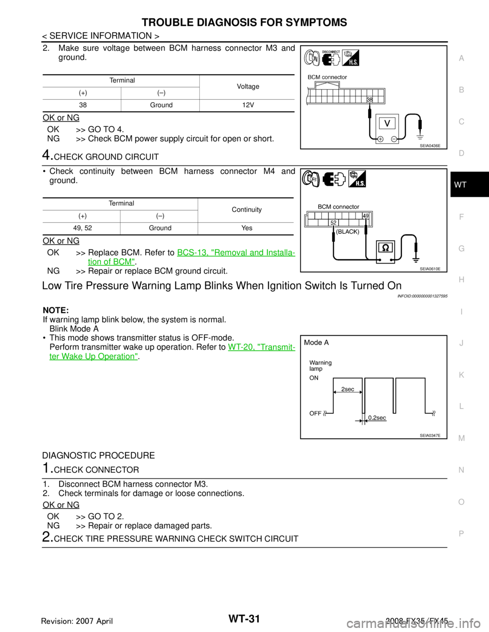
Make sure voltage between BCM harness connector M4 and
ground.
OK or NG
OK >> GO TO 3.
NG >> Check BCM power supply circuit for open or short.
3.CHECK POWER SUPPLY CIRCUIT (IGN)
1. Turn ignition switch ON.
Te r m i n a l Vol tag e
(+) (–)
42, 55 Ground 12V
SEIA0435E
3AA93ABC3ACD3AC03ACA3AC03AC63AC53A913A773A893A873A873A8E3A773A983AC73AC93AC03AC3
3A893A873A873A8F3A773A9D3AAF3A8A3A8C3A863A9D3AAF3A8B3A8C
Page 3871 of 3924
TROUBLE DIAGNOSIS FOR SYMPTOMSWT-31
< SERVICE INFORMATION >
C
DF
G H
I
J
K L
M A
B
WT
N
O P
2. Make sure voltage between BCM harness connector M3 and ground.
OK or NG
OK >> GO TO 4.
NG >> Check BCM power supply circuit for open or short.
4.CHECK GROUND CIRCUIT
Check continuity between BCM harness connector M4 and ground.
OK or NG
OK >> Replace BCM. Refer to BCS-13, "Removal and Installa-
tion of BCM".
NG >> Repair or replace BCM ground circuit.
Low Tire Pressure Warning Lamp Blin ks When Ignition Switch Is Turned On
INFOID:0000000001327595
NOTE:
If warning lamp blink below, the system is normal.
Blink Mode A
This mode shows transmitter status is OFF-mode.
Perform transmitter wake up operation. Refer to WT-20, "
Transmit-
ter Wake Up Operation".
DIAGNOSTIC PROCEDURE
1.CHECK CONNECTOR
1. Disconnect BCM harness connector M3.
2. Check terminals for damage or loose connections.
OK or NG
OK >> GO TO 2.
NG >> Repair or replace damaged parts.
2.CHECK TIRE PRESSURE WA RNING CHECK SWITCH CIRCUIT
Te r m i n a l
Voltag e
(+) (–)
38 Ground 12V
SEIA0436E
Te r m i n a l Continuity
(+) (–)
49, 52 Ground Yes
SEIA0610E
SEIA0347E
3AA93ABC3ACD3AC03ACA3AC03AC63AC53A913A773A893A873A873A8E3A773A983AC73AC93AC03AC3
3A893A873A873A8F3A773A9D3AAF3A8A3A8C3A863A9D3AAF3A8B3A8C
Page 3872 of 3924
WT-32
< SERVICE INFORMATION >
TROUBLE DIAGNOSIS FOR SYMPTOMS
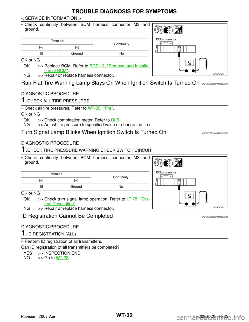
Check continuity between BCM harness connector M3 andground.
OK or NG
OK >> Replace BCM. Refer to BCS-13, "Removal and Installa-
tion of BCM".
NG >> Repair or replace harness connector.
Run-Flat Tire Warning Lamp Stays On When Ignition Switch Is Turned OnINFOID:0000000001327596
DIAGNOSTIC PROCEDURE
1.CHECK ALL TIRE PRESSURES
Check all tire pressures. Refer to WT-35, "
Tire".
OK or NG
OK >> Check combination meter. Refer to DI-5.
NG >> Adjust tire pressure to specified value or change the tires.
Turn Signal Lamp Blinks When Ignition Switch Is Turned OnINFOID:0000000001327597
DIAGNOSTIC PROCEDURE
1.CHECK TIRE PRESSURE WARNI NG CHECK SWITCH CIRCUIT
Check continuity between BCM harness connector M3 and ground.
OK or NG
OK >> Check turn signal lamp operation. Refer to LT-78, "Sys-
tem Description".
NG >> Repair or replace harness connector.
ID Registration Ca nnot Be CompletedINFOID:0000000001327598
DIAGNOSTIC PROCEDURE
1.ID REGISTRATION (ALL)
Perform ID registration of all transmitters.
Can ID registration of all transmitters be completed?
YES >> INSPECTION END
NO >> Go to WT-28
.
Te r m i n a l
Continuity
(+) (–)
15 Ground No
SEIA0438E
Te r m i n a l Continuity
(+) (–)
15 Ground No
SEIA0438E
3AA93ABC3ACD3AC03ACA3AC03AC63AC53A913A773A893A873A873A8E3A773A983AC73AC93AC03AC3
3A893A873A873A8F3A773A9D3AAF3A8A3A8C3A863A9D3AAF3A8B3A8C
Page 3875 of 3924

SERVICE DATA AND SPECIFICATIONS (SDS)
WT-35
< SERVICE INFORMATION >
C
D F
G H
I
J
K L
M A
B
WT
N
O P
SERVICE DATA AND SPECIFICATIONS (SDS)
Road WheelINFOID:0000000001327600
TireINFOID:0000000001327601
Unit: kPa (kg/cm2, psi)
Kind of wheel Aluminum Steel (for emergency use)
Maximum radial runout limit Lateral deflection Less than 0.3 mm (0.012 in) Less than 1.5 mm (0.059 in)
Vertical deflection Less than 0.3 mm (0.012 in) Less than 1.5 mm (0.059 in)
Maximum allowable unbalance Dynamic (At rim flange) Less than 5.0 g (0.2 oz) (one side) —
Static (At rim flange) Less than 20 g (0.7 oz) —
Tire size Air pressure
Front Rear
P265/60R18 109V 220 (2.2, 32) 220 (2.2, 32)
P265/50R20 106V 220 (2.2, 32) 220 (2.2, 32)
T175/90D18 110M 420 (4.2, 60) 420 (4.2, 60)
3AA93ABC3ACD3AC03ACA3AC03AC63AC53A913A773A893A873A873A8E3A773A983AC73AC93AC03AC3
3A893A873A873A8F3A773A9D3AAF3A8A3A8C3A863A9D3AAF3A8B3A8C