air INFINITI FX35 2008 Service Manual
[x] Cancel search | Manufacturer: INFINITI, Model Year: 2008, Model line: FX35, Model: INFINITI FX35 2008Pages: 3924, PDF Size: 81.37 MB
Page 1 of 3924
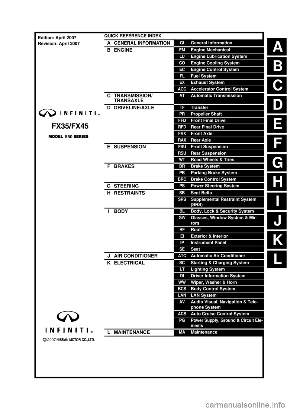
ABCDEFGHIJKLQUICK REFERENCE INDEX AGENERAL INFORMATIONGIGeneral InformationBENGINEEMEngine MechanicalLUEngine Lubrication SystemCOEngine Cooling SystemECEngine Control SystemFLFuel SystemEXExhaust SystemACCAccelerator Control SystemCTRANSMISSION/
TRANSAXLEATAutomatic TransmissionDDRIVELINE/AXLETFTransferPRPropeller ShaftFFDFront Final DriveRFDRear Final DriveFAXFront AxleRAXRear AxleESUSPENSIONFSUFront SuspensionRSURear SuspensionWTRoad Wheels & TiresFBRAKESBRBrake SystemPBParking Brake SystemBRCBrake Control SystemGSTEERINGPSPower Steering SystemHRESTRAINTSSBSeat BeltsSRSSupplemental Restraint System
(SRS)IBODYBLBody, Lock & Security SystemGWGlasses, Window System & Mir-
rorsRFRoofEIExterior & InteriorIPInstrument PanelSESeatJAIR CONDITIONERATCAutomatic Air ConditionerKELECTRICALSCStarting & Charging SystemLTLighting SystemDIDriver Information SystemWWWiper, Washer & HornBCSBody Control SystemLANLAN SystemAVAudio Visual, Navigation & Tele-
phone SystemACSAuto Cruise Control SystemPGPower Supply, Ground & Circuit Ele-
mentsLMAINTENANCEMAMaintenanceEdition: April 2007
Revision: April 2007
Page 4 of 3924
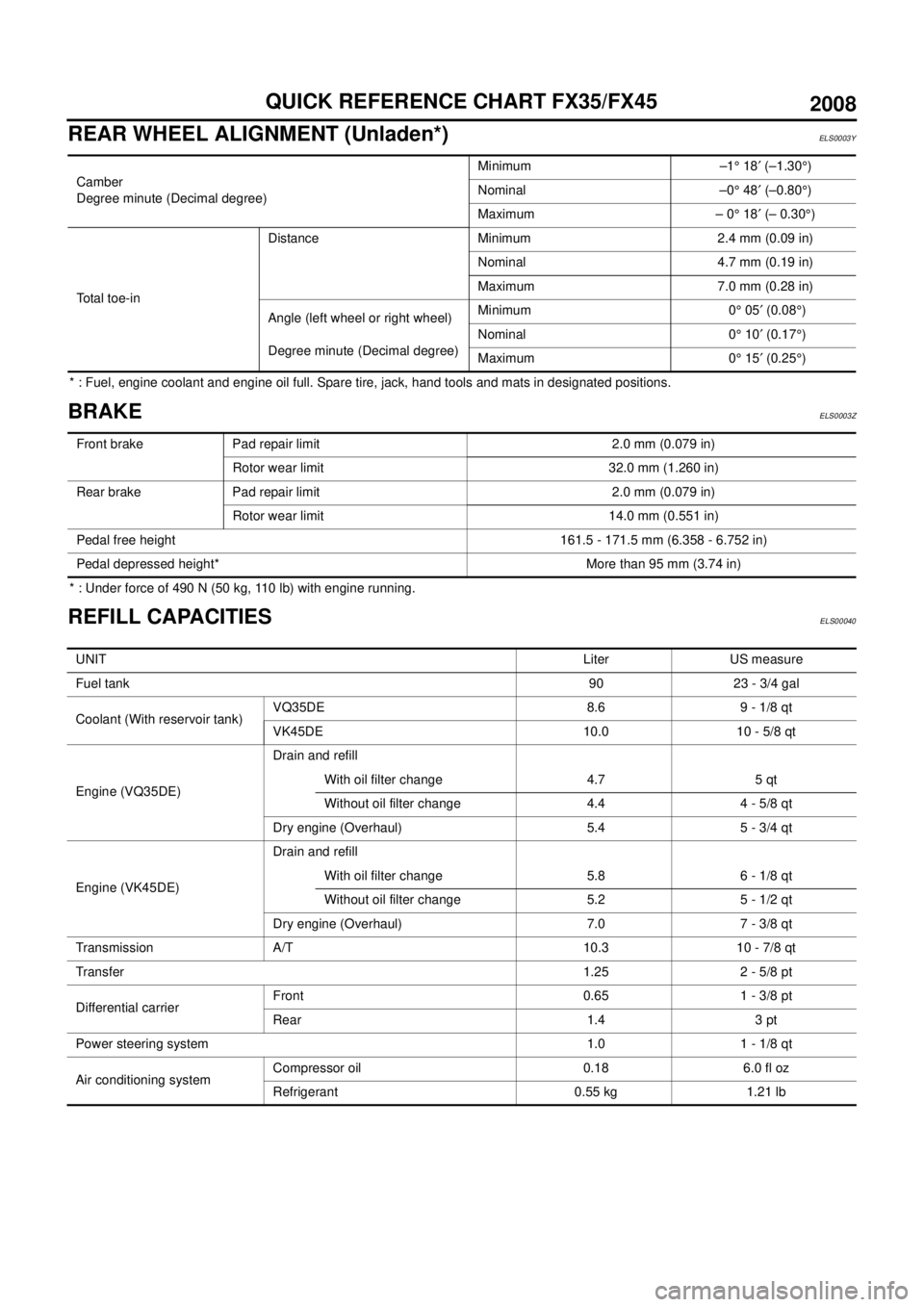
QUICK REFERENCE CHART FX35/FX45
REAR WHEEL ALIGNMENT (Unladen*)
ELS0003Y
* : Fuel, engine coolant and engine oil full. Spare tire, jack, hand tools and mats in designated positions.
BRAKEELS0003Z
* : Under force of 490 N (50 kg, 110 lb) with engine running.
REFILL CAPACITIESELS00040
Camber
Degree minute (Decimal degree)Minimum –1° 18′ (–1.30°)
Nominal –0° 48′ (–0.80°)
Maximum – 0° 18′ (– 0.30°)
Total toe-inDistance Minimum 2.4 mm (0.09 in)
Nominal 4.7 mm (0.19 in)
Maximum 7.0 mm (0.28 in)
Angle (left wheel or right wheel)
Degree minute (Decimal degree)Minimum 0° 05′ (0.08°)
Nominal 0° 10′ (0.17°)
Maximum 0° 15′ (0.25°)
Front brake Pad repair limit 2.0 mm (0.079 in)
Rotor wear limit 32.0 mm (1.260 in)
Rear brake Pad repair limit 2.0 mm (0.079 in)
Rotor wear limit 14.0 mm (0.551 in)
Pedal free height 161.5 - 171.5 mm (6.358 - 6.752 in)
Pedal depressed height* More than 95 mm (3.74 in)
UNITLiter US measure
Fuel tank90 23 - 3/4 gal
Coolant (With reservoir tank)VQ35DE 8.6 9 - 1/8 qt
VK45DE 10.0 10 - 5/8 qt
Engine (VQ35DE)Drain and refill
With oil filter change 4.7 5 qt
Without oil filter change 4.4 4 - 5/8 qt
Dry engine (Overhaul) 5.4 5 - 3/4 qt
Engine (VK45DE)Drain and refill
With oil filter change 5.8 6 - 1/8 qt
Without oil filter change 5.2 5 - 1/2 qt
Dry engine (Overhaul) 7.0 7 - 3/8 qt
Transmission A/T 10.3 10 - 7/8 qt
Transfer1.25 2 - 5/8 pt
Differential carrierFront 0.65 1 - 3/8 pt
Rear 1.4 3 pt
Power steering system 1.0 1 - 1/8 qt
Air conditioning systemCompressor oil 0.18 6.0 fl oz
Refrigerant 0.55 kg 1.21 lb
2008
Page 5 of 3924

ACC-1
ENGINE
C
DE
F
G H
I
J
K L
M
SECTION ACC
A
ACC
N
O P
CONTENTS
ACCELERATOR CONTROL SYSTEM
SERVICE INFORMATION .. ..........................2
PRECAUTIONS .............................................. .....2
Precaution for Supplemental Restraint System
(SRS) "AIR BAG" and "SEAT BELT PRE-TEN-
SIONER" ............................................................. ......
2
ACCELERATOR CONTROL SYSTEM ..............3
Component .......................................................... .....3
Removal and Installation ..........................................3
3AA93ABC3ACD3AC03ACA3AC03AC63AC53A913A773A893A873A873A8E3A773A983AC73AC93AC03AC3
3A893A873A873A8F3A773A9D3AAF3A8A3A8C3A863A9D3AAF3A8B3A8C
Page 6 of 3924
ACC-2
< SERVICE INFORMATION >
PRECAUTIONS
SERVICE INFORMATION
PRECAUTIONS
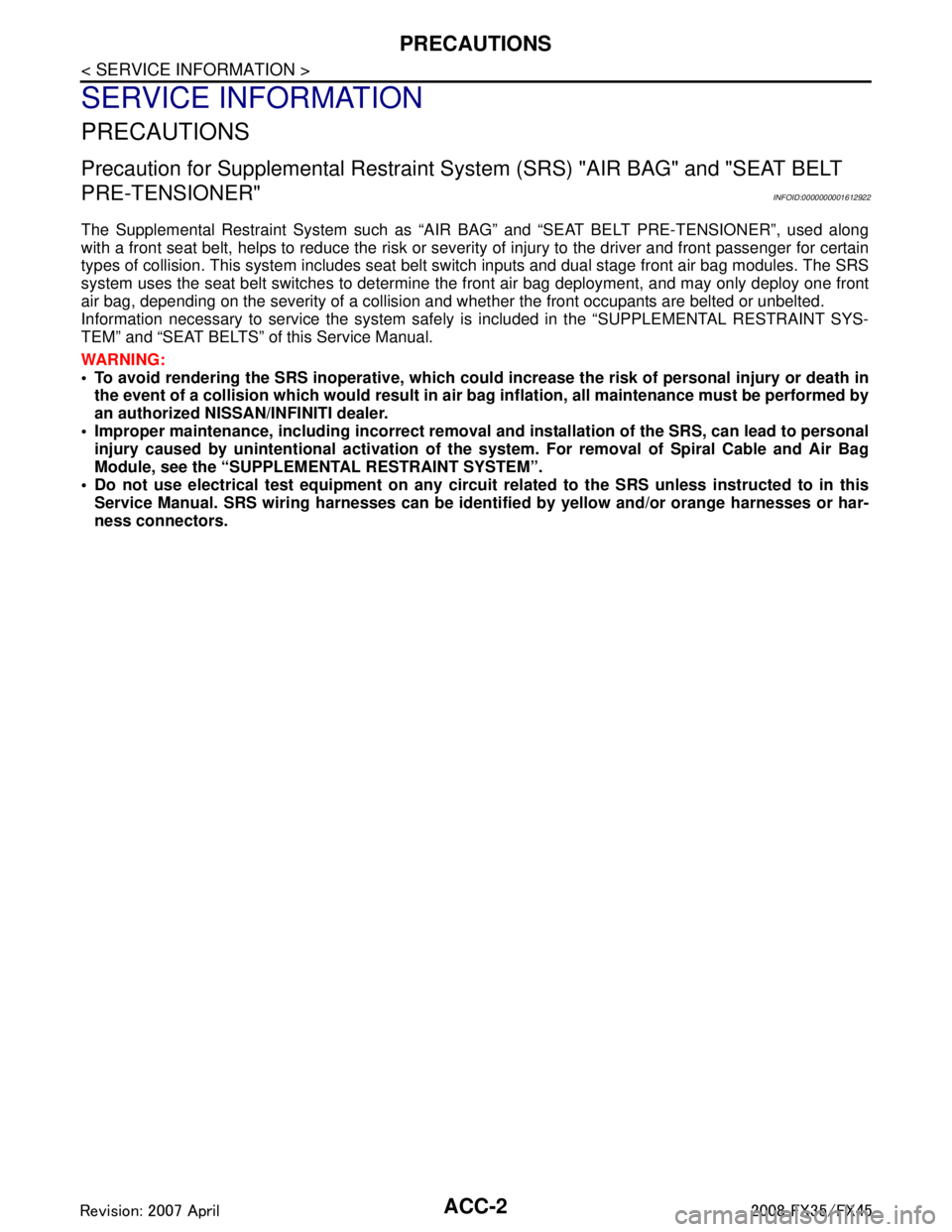
Precaution for Supplemental Restraint System (SRS) "AIR BAG" and "SEAT BELT
PRE-TENSIONER"
INFOID:0000000001612922
The Supplemental Restraint System such as “A IR BAG” and “SEAT BELT PRE-TENSIONER”, used along
with a front seat belt, helps to reduce the risk or severi ty of injury to the driver and front passenger for certain
types of collision. This system includes seat belt switch inputs and dual stage front air bag modules. The SRS
system uses the seat belt switches to determine the front air bag deployment, and may only deploy one front
air bag, depending on the severity of a collision and w hether the front occupants are belted or unbelted.
Information necessary to service the system safely is included in the “SUPPLEMENTAL RESTRAINT SYS-
TEM” and “SEAT BELTS” of this Service Manual.
WARNING:
• To avoid rendering the SRS inopera tive, which could increase the risk of personal injury or death in
the event of a collision which would result in air bag inflation, all maintenance must be performed by
an authorized NISS AN/INFINITI dealer.
Improper maintenance, including in correct removal and installation of the SRS, can lead to personal
injury caused by unintent ional activation of the system. For re moval of Spiral Cable and Air Bag
Module, see the “SUPPLEMEN TAL RESTRAINT SYSTEM”.
Do not use electrical test equipmen t on any circuit related to the SRS unless instructed to in this
Service Manual. SRS wiring harnesses can be identi fied by yellow and/or orange harnesses or har-
ness connectors.
3AA93ABC3ACD3AC03ACA3AC03AC63AC53A913A773A893A873A873A8E3A773A983AC73AC93AC03AC3
3A893A873A873A8F3A773A9D3AAF3A8A3A8C3A863A9D3AAF3A8B3A8C
Page 8 of 3924
ACS-1
ELECTRICAL
C
DE
F
G H
I
J
L
M
SECTION ACS
A
B
ACS
N
O P
CONTENTS
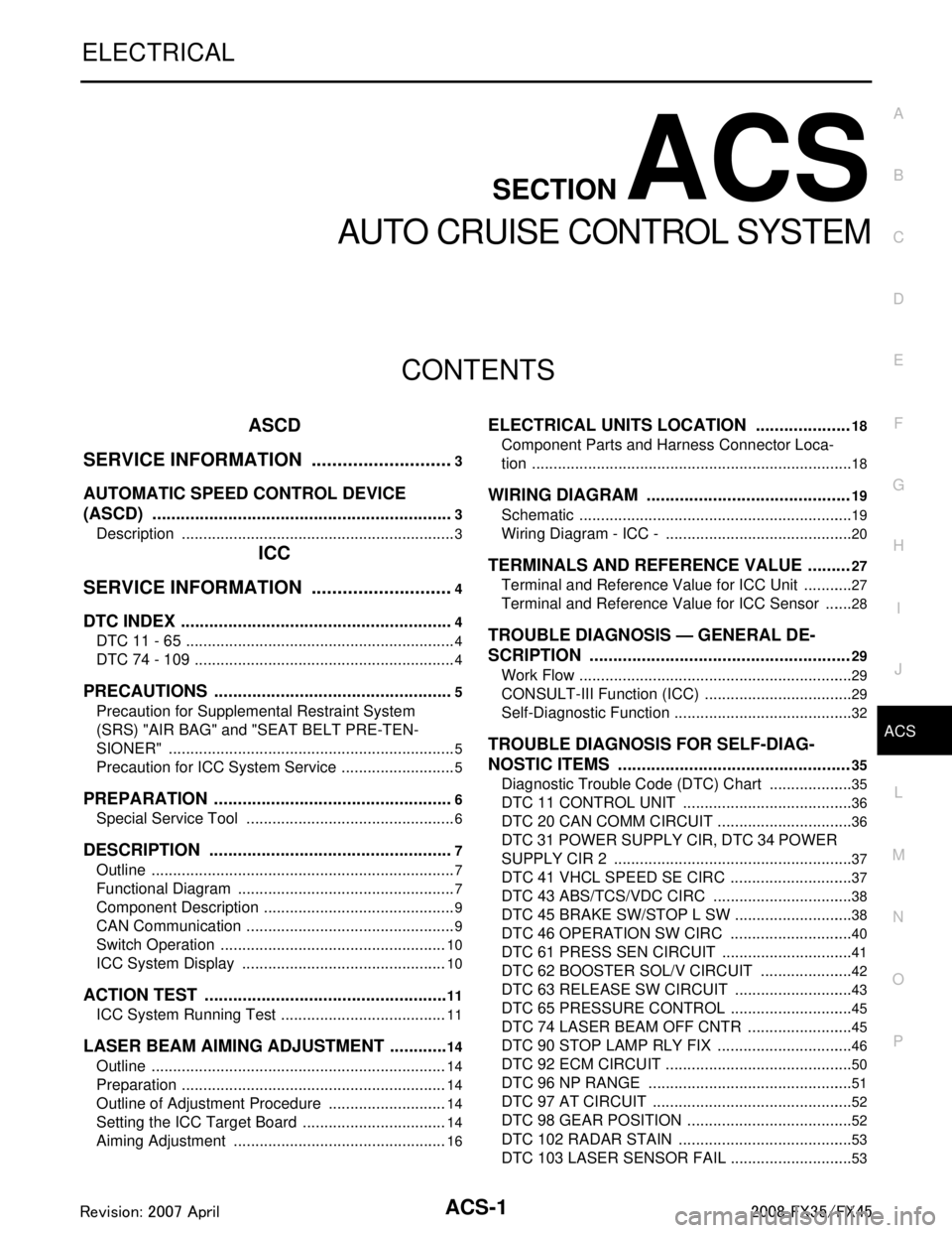
AUTO CRUISE CONTROL SYSTEM
ASCD
SERVICE INFORMATION .. ..........................
3
AUTOMATIC SPEED CONTROL DEVICE
(ASCD) ........................................................... .....
3
Description .......................................................... ......3
ICC
SERVICE INFORMATION .. ..........................
4
DTC INDEX ..................................................... .....4
DTC 11 - 65 ......................................................... ......4
DTC 74 - 109 .............................................................4
PRECAUTIONS ...................................................5
Precaution for Supplemental Restraint System
(SRS) "AIR BAG" and "SEAT BELT PRE-TEN-
SIONER" ............................................................. ......
5
Precaution for ICC System Service ...........................5
PREPARATION ...................................................6
Special Service Tool ........................................... ......6
DESCRIPTION ....................................................7
Outline ................................................................. ......7
Functional Diagram ...................................................7
Component Description .............................................9
CAN Communication .................................................9
Switch Operation .....................................................10
ICC System Display ................................................10
ACTION TEST ....................................................11
ICC System Running Test ................................... ....11
LASER BEAM AIMING ADJUSTMENT .............14
Outline ................................................................. ....14
Preparation ..............................................................14
Outline of Adjustment Procedure ............................14
Setting the ICC Target Board ..................................14
Aiming Adjustment ..................................................16
ELECTRICAL UNITS LOCATION ....................18
Component Parts and Harness Connector Loca-
tion ....................................................................... ....
18
WIRING DIAGRAM ...........................................19
Schematic ................................................................19
Wiring Diagram - ICC - ............................................20
TERMINALS AND REFERENCE VALUE .........27
Terminal and Reference Value for ICC Unit ............27
Terminal and Reference Value for ICC Sensor ... ....28
TROUBLE DIAGNOSIS — GENERAL DE-
SCRIPTION .......................................................
29
Work Flow ................................................................29
CONSULT-III Function (ICC) ...................................29
Self-Diagnostic Function ..........................................32
TROUBLE DIAGNOSIS FOR SELF-DIAG-
NOSTIC ITEMS .................................................
35
Diagnostic Trouble Code (DTC) Chart ....................35
DTC 11 CONTROL UNIT ........................................36
DTC 20 CAN COMM CIRCUIT ................................36
DTC 31 POWER SUPPLY CIR, DTC 34 POWER
SUPPLY CIR 2 ........................................................
37
DTC 41 VHCL SPEED SE CIRC .............................37
DTC 43 ABS/TCS/VDC CIRC .................................38
DTC 45 BRAKE SW/STOP L SW ............................38
DTC 46 OPERATION SW CIRC ......................... ....40
DTC 61 PRESS SEN CIRCUIT ...............................41
DTC 62 BOOSTER SOL/V CIRCUIT .................. ....42
DTC 63 RELEASE SW CIRCUIT ............................43
DTC 65 PRESSURE CONTRO L .............................45
DTC 74 LASER BEAM OFF CNTR ..................... ....45
DTC 90 STOP LAMP RLY FIX ................................46
DTC 92 ECM CIRCUIT ............................................50
DTC 96 NP RANGE ................................................51
DTC 97 AT CIRCUIT ...............................................52
DTC 98 GEAR POSITION .......................................52
DTC 102 RADAR STAIN .........................................53
DTC 103 LASER SENSOR FAIL .............................53
3AA93ABC3ACD3AC03ACA3AC03AC63AC53A913A773A893A873A873A8E3A773A983AC73AC93AC03AC3
3A893A873A873A8F3A773A9D3AAF3A8A3A8C3A863A9D3AAF3A8B3A8C
Page 12 of 3924

PRECAUTIONSACS-5
< SERVICE INFORMATION > [ICC]
C
D
E
F
G H
I
J
L
M A
B
ACS
N
O P
PRECAUTIONS
Precaution for Supplemental Restraint System (SRS) "AIR BAG" and "SEAT BELT
PRE-TENSIONER"
INFOID:0000000001612901
The Supplemental Restraint System such as “A IR BAG” and “SEAT BELT PRE-TENSIONER”, used along
with a front seat belt, helps to reduce the risk or severi ty of injury to the driver and front passenger for certain
types of collision. This system includes seat belt switch inputs and dual stage front air bag modules. The SRS
system uses the seat belt switches to determine the front air bag deployment, and may only deploy one front
air bag, depending on the severity of a collision and whether the front occupants are belted or unbelted.
Information necessary to service the system safely is included in the “SUPPLEMENTAL RESTRAINT SYS-
TEM” and “SEAT BELTS” of this Service Manual.
WARNING:
To avoid rendering the SRS inoper ative, which could increase the risk of personal injury or death in
the event of a collision which would result in air bag inflation, all maintenance must be performed by
an authorized NISSAN/INFINITI dealer.
Improper maintenance, including in correct removal and installation of the SRS, can lead to personal
injury caused by unintentional act ivation of the system. For removal of Spiral Cable and Air Bag
Module, see the “SUPPLEMEN TAL RESTRAINT SYSTEM”.
Do not use electrical test equipm ent on any circuit related to the SRS unless instructed to in this
Service Manual. SRS wiring harnesses can be identi fied by yellow and/or orange harnesses or har-
ness connectors.
Precaution for ICC System ServiceINFOID:0000000001328803
Never look straight into the laser beam discharger when adjusting laser beam aiming.
Turn the MAIN switch OFF in conditions similar to dr iving, such as free rollers or a chassis dynamometer.
Do not use the ICC sensor removing from v ehicle, disassemble, or remodel the sensor.
Erase DTC when replacing parts of ICC system, then c heck the operation of ICC system after adjusting laser
beam aiming if necessary.
3AA93ABC3ACD3AC03ACA3AC03AC63AC53A913A773A893A873A873A8E3A773A983AC73AC93AC03AC3
3A893A873A873A8F3A773A9D3AAF3A8A3A8C3A863A9D3AAF3A8B3A8C
Page 40 of 3924

TROUBLE DIAGNOSIS — GENERAL DESCRIPTIONACS-33
< SERVICE INFORMATION > [ICC]
C
D
E
F
G H
I
J
L
M A
B
ACS
N
O P
1. Go to operation check after asking the cust omer for symptom information. Refer to ACS-11, "ICC System
Running Test".
2. Stop vehicle, turn ignition swit ch OFF, then connect CONSULT-III.
3. With engine started, check “Self Diagnostic Result” of ICC system.
4. Self-diagnostic result appears on screen. If “NO DTC ·· ·” is shown, check ICC warning lamp. If any mal-
function is indicated, GO TO step 5.
5. According to ACS-35, "
Diagnostic Trouble Code (DTC) Chart", perform appropriate check, and repair or
replace malfunctioning part as necessary.
6. Turn ignition switch OFF.
7. Start the engine and select “Self Diagnosti c Result” of ICC system, and erase DTC.
NOTE:
If the memory does not erase, go to 5.
8. Perform ICC system running test (drive vehicle wi th ICC system ON), and make sure that ICC warning
lamp does not illuminate.
WITHOUT CONSULT-III
1. Go to operation check after asking the cust omer for symptom information. Refer to ACS-11, "ICC System
Running Test".
2. Stop the vehicle to start the self-diagnosis.
3. Turn ignition switch OFF.
4. From 5 seconds through 15 seconds after turning ignition switch ON, press RESUME/ACCELERATE switch 5 times, and SET/
COAST switch 5 times.
NOTE:
Never start engine.
Never turn the MAIN switch ON.
When operation above is not completed from 5 secondsthrough 15 seconds, start again from above go to 3.
If self-diagnosis mode cannot be started after several
attempts, the ICC unit may have had malfunction. Repair or
replace it. Refer to ACS-59, "
SELF-DIAGNOSIS BY ICC SYS-
TEM DISPLAY WILL NOT RUN".
5. When self-diagnosis mode is started, DTC are shown on set vehicle speed indicator.
NOTE:
DTC will disappear after 5 minutes.
When more than one malfunction is detected, a maxi mum of 3 code numbers can be stored; the latest
malfunction will be displayed first.
6. Check ACS-35, "
Diagnostic Trouble Code (DTC) Chart", and repair or replace if necessary.
7. After repair, erase DTC stored in the ICC unit.
PKIA9675E
PKIA9820E
3AA93ABC3ACD3AC03ACA3AC03AC63AC53A913A773A893A873A873A8E3A773A983AC73AC93AC03AC3
3A893A873A873A8F3A773A9D3AAF3A8A3A8C3A863A9D3AAF3A8B3A8C
Page 43 of 3924

ACS-36
< SERVICE INFORMATION >[ICC]
TROUBLE DIAGNOSIS FOR
SELF-DIAGNOSTIC ITEMS
DTC 11 CONTROL UNIT
INFOID:0000000001328826
1.PERFORM SELF-DIAGNOSIS OF ICC SYSTEM
1. Perform self-diagnosis of ICC system.
2. Check if any item other than “DTC 11 CONTRO L UNIT” is indicated on self-diagnosis display.
Is any indicated?
YES >> 1. Repair or replace applicable item. 2. Erase DTC and perform ICC system running test. Then perform self-diagnosis of ICC system
again.
NO >> 1. Replace ICC unit.
2. Erase DTC and perform ICC system running test. Then perform self-diagnosis of ICC system
again.
DTC 20 CAN COMM CIRCUITINFOID:0000000001328827
1.PERFORM SELF-DIAGNOSIS OF ICC SYSTEM
1. Turn ignition switch ON and wait for 2 second or more.
2. Check self-diagnosis of ICC system.
Is
“CAN COMM CIRCUIT” displayed?
YES >> Refer to LAN-14, "Trouble Diagnosis Flow Chart".
NO >> Refer to GI-35, "
CONSULT-III/GST Data Link Connector (DLC) Circuit".
92 ECM CIRCUIT ×××× ECM malfunction
Accelerator pedal position sensor
malfunction
ICC unit malfunction ACS-50
96 NP RANGE
××× Park/neutral position switch har-
ness is open or shorted.
Park/neutral position switch mal- function.
TCM malfunction ACS-51
97 AT CIRCUIT
××× TCM malfunctionACS-52
98 GEAR POSITION ××× TCM malfunction
AT turbine revolution sensor mal-
function
AT vehicle speed sensor malfunc-
tion ACS-52
102 RADAR STAIN
×× × ICC sensor body window has con-
tamination. ACS-53
103 LASER SENSOR FAIL
×× × ICC sensor internal malfunctionACS-53
104 LASER AIMING INCMP ×× × Laser beam aiming of ICC sensor
is not adjusted. ACS-54
107 LASER COMM FAIL
×× × CAN data received by ICC sensor
is strange (from ICC unit, combina-
tion meter or ECM). ACS-54
109 LASER HIGH TEMP
×× × Temperature around ICC sensor is
excessively high. ACS-54
DTC
No. CONSULT-III
screen terms ICC
system
warning lamp Fail-safe
Malfunctions detected where... Refer-
ence
page
Vehicle-
to-
vehicle
distance control mode Conven-
tional
(fixed
speed) cruise
control mode Brake as-
sist (with
preview
function)
3AA93ABC3ACD3AC03ACA3AC03AC63AC53A913A773A893A873A873A8E3A773A983AC73AC93AC03AC3
3A893A873A873A8F3A773A9D3AAF3A8A3A8C3A863A9D3AAF3A8B3A8C
Page 44 of 3924

TROUBLE DIAGNOSIS FOR SELF-DIAGNOSTIC ITEMS
ACS-37
< SERVICE INFORMATION > [ICC]
C
D
E
F
G H
I
J
L
M A
B
ACS
N
O P
DTC 31 POWER SUPPLY CIR, DT C 34 POWER SUPPLY CIR 2INFOID:0000000001328828
1.CHECK CONNECTOR ICC UNIT
1. Turn ignition switch OFF.
2. Disconnect ICC unit connector, and connect it securely again.
3. Erase DTC and perform ICC running test. Then perform self-diagnosis of ICC system again.
Is malfunction indicated?
YES >> GO TO 2.
NO >> Poor connector connection 1. Check connector. (Check connector housing for disconnected, loose, bent, and collapsed ter-
minals. If any malfunction is detected, repair applicable part.)
2. Erase DTC and perform ICC running test. T hen perform self-diagnosis of ICC system again.
2.CHECK POWER SUPPLY CIRCUIT FOR ICC UNIT
1. Turn ignition switch ON.
2. Check voltage between ICC unit harness connector and ground.
OK or NG
OK >> GO TO 3.
NG >> 1. Repair ICC unit power supply harness. 2. Erase DTC and perform ICC syst em running test. Then perform self-diagnosis of ICC system
again.
3.CHECK GROUND CIRCUIT FOR ICC UNIT
1. Turn ignition switch OFF.
2. Disconnect ICC unit connector.
3. Check continuity between ICC unit harness connector and ground.
OK or NG
OK >> 1. Replace ICC unit. 2. Erase DTC and perform ICC syst em running test. Then perform self-diagnosis of ICC system
again.
NG >> 1. Repair ICC unit ground harness. 2. Erase DTC and perform ICC syst em running test. Then perform self-diagnosis of ICC system
again.
DTC 41 VHCL SPEED SE CIRCINFOID:0000000001328829
1.PERFORM SELF-DIAGNOSIS OF ICC SYSTEM
1. Perform self-diagnosis of ICC system.
2. Check if “DTC 43 ABS/TCS/VDC CIRC” or “DTC 20 CAN COMM CIRCUIT” other than “DTC 41 VHCL
SPEED SE CIRC” is indicated in self-diagnosis item in the display.
Is any indicated?
YES >> 1. Repair or replace applicable item.
ICC unit connector Te r m i n a l
Voltage (Approx.)
(+) ( −)
M89 33
Ground Battery voltage
42
SKIA1173E
ICC unit con-
nector Te r m i n a l
Ground Continuity
M88 19
Ye s
20
M89 46
SKIA6650E
3AA93ABC3ACD3AC03ACA3AC03AC63AC53A913A773A893A873A873A8E3A773A983AC73AC93AC03AC3
3A893A873A873A8F3A773A9D3AAF3A8A3A8C3A863A9D3AAF3A8B3A8C
Page 45 of 3924

ACS-38
< SERVICE INFORMATION >[ICC]
TROUBLE DIAGNOSIS FOR
SELF-DIAGNOSTIC ITEMS
2. Erase DTC and perform ICC system running test. Then perform self-diagnosis of ICC system
again.
NO >> GO TO 2.
2.CHECK AT VEHICLE SPEED SENSOR
With “Data Monitor” of “ICC”, check “VHCL SPD AT” operates normally.
OK or NG
OK >> 1. Replace ICC unit. 2. Erase DTC and perform ICC system running test. Then perform self-diagnosis of ICC system
again.
NG >> 1. Perform self-diagnosis of TCM. 2. After repairing or replacing applicable item, erase DTC and perform ICC system running test.
Then perform self-diagnosis of ICC system again.
DTC 43 ABS/TCS/VDC CIRCINFOID:0000000001328830
1.PERFORM SELF-DIAGNOSIS OF ICC SYSTEM
1. Perform self-diagnosis of ICC system.
2. Check if “DTC 20 CAN COMM CIRCUIT” other than “D TC 43 ABS/TCS/VDC CIRC” is indicated in self-
diagnosis item in the display.
Is it indicated?
YES >> 1. Repair or replace applicable item. 2. Erase DTC and perform ICC system running test. Then perform self-diagnosis of ICC system
again.
NO >> GO TO 2.
2.PERFORM SELF-DIAGNOSIS OF ABS ACTUATOR AND ELECTRIC UNIT (CONTROL UNIT)
1. Perform self-diagnosis of ABS actuator and electric unit (control unit). Refer to BRC-26, "
Self-Diagnosis".
2. Check if malfunction is indicated.
Is malfunction indicated?
YES >> 1. Repair or replace applicable item. 2. Erase DTC and perform ICC system running test. Then perform self-diagnosis of ICC system
again.
NO >> 1. Replace ICC unit. 2. Erase DTC and perform ICC system running test. Then perform self-diagnosis of ICC system
again.
DTC 45 BRAKE SW/STOP L SWINFOID:0000000001328831
1.CHECK CONNECTOR FOR ICC UNIT
1. Turn ignition switch OFF.
2. Disconnect ICC unit connector, and connect it securely again.
3. Erase DTC and perform ICC system running test. T hen perform self-diagnosis of ICC system again.
Is malfunction indicated?
YES >> GO TO 2.
NO >> Poor connector connection 1. Check connector. (Check connector housing for disconnected, loose, bent, and collapsed ter-minals. If any malfunction is detected, repair applicable part.)
2. Erase DTC and perform ICC system running test. Then perform self-diagnosis of ICC system
again.
2.CHECK STOP LAMP SWITCH AND ICC BRAKE SWITCH
With “Data Monitor” of “ICC”, check if “STO P LAMP SW” and “BRAKE SW” are operated normally.
OK or NG
OK >> 1. Replace ICC unit. 2. Erase DTC and perform ICC system running test. Then perform self-diagnosis of ICC system
again.
NG-1 >> “BRAKE SW” NG: GO TO 3.
3AA93ABC3ACD3AC03ACA3AC03AC63AC53A913A773A893A873A873A8E3A773A983AC73AC93AC03AC3
3A893A873A873A8F3A773A9D3AAF3A8A3A8C3A863A9D3AAF3A8B3A8C