INFINITI G-CONVERTIBLE 2012 Owners Manual
Manufacturer: INFINITI, Model Year: 2012, Model line: G-CONVERTIBLE, Model: INFINITI G-CONVERTIBLE 2012Pages: 474, PDF Size: 3.63 MB
Page 451 of 474
9-14Technical and consumer information
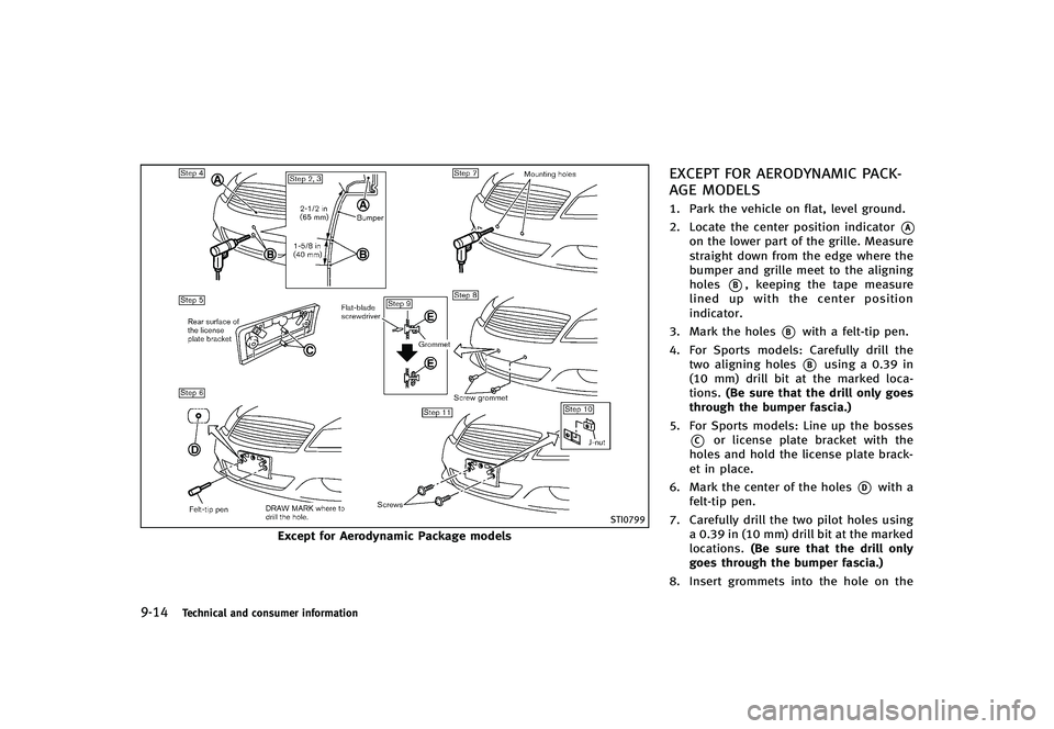
STI0799
Except for Aerodynamic Package models
EXCEPT FOR AERODYNAMIC PACK-
AGE MODELS
GUID-3D1C304A-406E-415C-8D62-CDAE8F0DB8AE1. Park the vehicle on flat, level ground.
2. Locate the center position indicator
*Aon the lower part of the grille. Measure
straight down from the edge where the
bumper and grille meet to the aligning
holes
*B, keeping the tape measure
lined up with the center position
indicator.
3. Mark the holes
*Bwith a felt-tip pen.
4. For Sports models: Carefully drill the two aligning holes
*Busing a 0.39 in
(10 mm) drill bit at the marked loca-
tions. (Be sure that the drill only goes
through the bumper fascia.)
5. For Sports models: Line up the bosses
*Cor license plate bracket with the
holes and hold the license plate brack-
et in place.
6. Mark the center of the holes
*Dwith a
felt-tip pen.
7. Carefully drill the two pilot holes using a 0.39 in (10 mm) drill bit at the marked
locations. (Be sure that the drill only
goes through the bumper fascia.)
8. Insert grommets into the hole on the
Page 452 of 474
fascia.
9. Insert a flat-blade screwdriver into the grommet hole to add 908 turn onto the
part
*E.
10. Insert a J-nut into the license plate bracket before placing the license plate
bracket on the fascia.
11. Install the license plate bracket with screws.
12. Install the license plate with bolts that are no longer than 0.55 in (14 mm).
Technical and consumer information9-15
Page 453 of 474
9-16Technical and consumer information
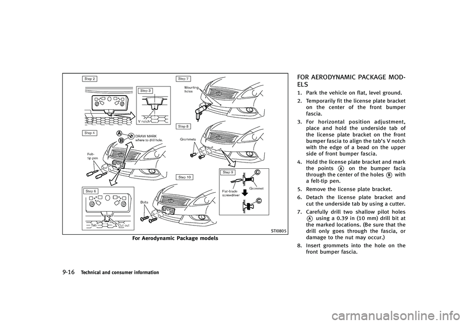
STI0805
For Aerodynamic Package models
FOR AERODYNAMIC PACKAGE MOD-
ELS
GUID-5684B0DB-28E1-48BD-903A-861C09C8D7EF1. Park the vehicle on flat, level ground.
2. Temporarily fit the license plate bracketon the center of the front bumper
fascia.
3. For horizontal position adjustment,
place and hold the underside tab of
the license plate bracket on the front
bumper fascia to align the tab’s V notch
with the edge of a bead on the upper
side of front bumper fascia.
4. Hold the license plate bracket and mark the points
*Aon the bumper facia
through the center of the holes
*Bwith
a felt-tip pen.
5. Remove the license plate bracket.
6. Detach the license plate bracket and cut the underside tab by using a cutter.
7. Carefully drill two shallow pilot holes
*Ausing a 0.39 in (10 mm) drill bit at
the marked locations. (Be sure that the
drill only goes through the fascia, or
damage to the nut may occur.)
8. Insert grommets into the hole on the front bumper fascia.
Page 454 of 474
9. Insert a flat-blade screwdriver into thegrommet hole to add a 908 turn onto
the part
*C.
10. Install the license plate bracket with the bolts.
11. Install the license plate with bolts that are not longer than 0.55 in (14 mm).
GUID-FA938551-A2AF-4C28-8038-A1023026D8A8
WARNING
.It is extremely dangerous to ride
in a cargo area inside the vehicle.
In a collision, people riding in
these areas are more likely to be
seriously injured or killed.
.Do not allow people to ride in any
area of vehicle that is not
equipped with seats and seat
belts.
.Be sure everyone in your vehicle is
in a seat and using a seat belt
properly.
TERMSGUID-AFE6BEE1-94DB-40B4-B4CC-6439DC599E16It is important to familiarize yourself
with the following terms before
loading your vehicle:
.Curb Weight (actual weight of yourvehicle) - vehicle weight includ-
ing: standard and optional equip-
ment, fluids, emergency tools,
and spare tire assembly. This weightdoes not
include passen-
gers and cargo.
.GVW (Gross Vehicle Weight) - curb weight plus the combined weight
of passengers and cargo.
.GVWR (Gross Vehicle Weight Rat-ing) - maximum total combined
weight of the unloaded vehicle,
passengers, luggage, hitch, trailer
tongue load and any other op-
tional equipment. This informa-
tion is located on the F.M.V.S.S./
C.M.V.S.S. label.
.GAWR (Gross Axle Weight Rating) -maximum weight (load) limit spe-
cified for the front or rear axle.
This information is located on the
F.M.V.S.S./C.M.V.S.S. label.
.GCWR (Gross Combined WeightRating) - The maximum total
weight rating of the vehicle, pas-
sengers, cargo, and trailer.
.Vehicle Capacity Weight, Loadlimit, Total load capacity - max-
imum total weight limit specified
Technical and consumer information9-17
VEHICLE LOADING INFORMATION
Page 455 of 474
9-18Technical and consumer information
of the load (passengers and car-
go) for the vehicle. This is the
maximum combined weight of
occupants and cargo that can be
loaded into the vehicle. If the
vehicle is used to tow a trailer,
the trailer tongue weight must be
included as part of the cargo load.
This information is located on the
Tire and Loading Information la-
bel.
.Cargo capacity - permissibleweight of cargo, the weight of
total occupants weight subtracted
from the load limit.STI0365
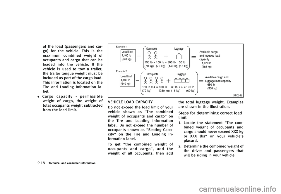
VEHICLE LOAD CAPACITYGUID-69EFC661-5277-4332-B1F2-AE9E453B2BA0Do not exceed the load limit of your
vehicle shown as “The combined
weight of occupants and cargo” on
the Tire and Loading Information
label. Do not exceed the number of
occupants shown as “Seating Capa-
city” on the Tire and Loading In-
formation label.
To get “the combined weight of
occupants and cargo”, add the
weight of all occupants, then add the total luggage weight. Examples
are shown in the illustration.
Steps for determining correct load
limit
GUID-83E2AD6E-0268-4507-924F-F5E14B3CE53F1.Locate the statement
“The com-
bined weight of occupants and
cargo should never exceed XXX kg
or XXX lbs” on your vehicle’s
placard.
2.Determine the combined weight of
the driver and passengers that
will be riding in your vehicle.
Page 456 of 474
3.Subtract the combined weight of
the driver and passengers from
XXX kg or XXX lbs.
4.The resulting figure equals the
available amount of cargo and
luggage load capacity. For exam-
ple, if the XXX amount equals
1400 lbs. and there will be five
150 lb. passengers in your vehi-
cle, the amount of available cargo
and luggage load capacity is 650
lbs. (1400−750 (5 x 150) = 650
lbs or 640 −340 (5 x 70) = 300
kg.)
5.Determine the combined weight of
luggage and cargo being loaded
on the vehicle. That weight may
not safely exceed the available
cargo and luggage load capacity
calculated in Step 4.
6.If your vehicle will be towing a
trailer, load from your trailer will
be transferred to your vehicle.
Consult this manual to determine
how this reduces the available cargo and luggage load capacity
of your vehicle.
Before driving a loaded vehicle,
confirm that you do not exceed the
Gross Vehicle Weight Rating (GVWR)
or the Gross Axle Weight Rating
(GAWR) for your vehicle. (See “Mea-
surement of weights” (P.9-20).)
Also check tires for proper inflation
pressures. See the Tire and Loading
Information label.
LOADING TIPSGUID-FE9B5593-CAC3-4828-9578-88327F3E0DAF.The GVW must not exceed GVWR or GAWR as specified on the F.M.V.
S.S./C.M.V.S.S. certification label.
.Do not load the front and rear axleto the GAWR. Doing so will exceed
the GVWR.
WARNING
. Properly secure all cargo to help
prevent it from sliding or shifting.
Do not place cargo higher than the seatbacks. In a sudden stop or
collision, unsecured cargo could
cause personal injury.
. Do not load your vehicle any
heavier than the GVWR or the
maximum front and rear GAWRs.
If you do, parts of your vehicle can
break, tire damage could occur, or
it can change the way your vehicle
handles. This could result in loss
of control and cause personal
injury.
. Overloading could not only short-
en the life of your vehicle and the
tires, but also could lead to
hazardous vehicle handling and
long braking distance. This may
cause a premature tire malfunc-
tion, which could result in a
serious accident and personal in-
jury. Failures caused by overload-
ing are not covered by the
vehicle’s warranty.
Technical and consumer information9-19
Page 457 of 474
9-20Technical and consumer information
MEASUREMENT OF WEIGHTSGUID-93BC7735-498A-4D30-8D82-02BCA761EB77Secure loose items to prevent weight
shifts that could affect the balance of
your vehicle. When the vehicle is
loaded, drive to a scale and weigh
the front and the rear wheels sepa-
rately to determine axle loads. In-
dividual axle loads should not
exceed either of the gross axle
weight ratings (GAWR). The total of
the axle loads should not exceed the
gross vehicle weight rating (GVWR).
These ratings are given on the
vehicle certification label. If weight
ratings are exceeded, move or re-
move items to bring all weights
below the ratings.
GUID-03C8D242-808F-4159-BB5A-9D1475396ECD
Do not tow a trailer with your
vehicle.
FLAT TOWINGGUID-1A5DE173-BB7F-45B0-A5B0-F0DB053F125DTowing your vehicle with all four wheels on
the ground is sometimes called flat towing.
This method is sometimes used when
towing a vehicle behind a recreational
vehicle, such as a motor home.
CAUTION
.Failure to follow these guidelines can
result in severe transmission damage.
. Whenever flat towing your vehicle, al-
ways tow forward, never backward.
. DO NOT tow any automatic transmission
vehicle with all four wheels on the
ground (flat towing). Doing so WILL
DAMAGE internal transmission parts
due to lack of transmission lubrication.
. For emergency towing procedures refer
to“Towing recommended by INFINITI”
(P.6-18) of this manual.
Automatic transmissionGUID-967E7021-7B09-40D8-BF80-AEAB3F63F03BTo tow a vehicle equipped with an auto-
matic transmission, an appropriate vehicle
dolly MUST be placed under the towed
vehicle’s drive wheels. Alwaysfollow the
dolly manufacturer’s recommendations
when using their product.
Manual transmissionGUID-C066DC0F-F9A6-4CD6-A341-CE5F2EB3898C. Always tow with the manual transmis-
sion in Neutral.
. Your vehicle speed should never exceed
70 MPH (112 km/h) when flat towing
your vehicle.
. After towing 500 miles, start and idle
the engine with the transmission in
Neutral for two minutes. Failure to idle
the engine after every 500 miles of
towing may cause damage to the
transmission’s internal parts.
TOWING A TRAILER
Page 458 of 474

GUID-4DCAB315-AC66-4A49-A484-5C2927B4F2E4DOT (Department Of Transportation) Qual-
ity Grades: All passenger car tires must
conform to federal safety requirements in
addition to these grades.
Quality grades can be found where applic-
able on the tire sidewall between tread
shoulder and maximum section width. For
example:
Treadwear 200 Traction AA Temperature A
TREADWEARGUID-61A676A7-9B91-4A79-A32F-E8D628C55791The treadwear grade is a comparative
rating based on the wear rate of the tire
when tested under controlled conditions
on a specified government test course. For
example, a tire graded 150 would wear one
and one-half (1 1/2) times as well on the
government course as a tire graded 100.
The relative performance of tires depends
upon actual conditions of their use, how-
ever, and may depart significantly from the
norm due to variations in driving habits,
service practices and differences in road
characteristics and climate.
TRACTION AA, A, B AND CGUID-BA7990B4-C685-4A1D-A234-3E4A1FA8B404The traction grades, from highest to low-
est, are AA, A, B and C. Those grades
represent the tire’s ability to stop on wet
pavement as measured under controlled
conditions on specified government test
surfaces of asphalt and concrete. A tire
marked C may have poor traction perfor-
mance.
WARNING
The traction grade assigned to this tire is
based on straight-ahead braking traction
tests, and does not include acceleration,
cornering, hydroplaning, or peak traction
characteristics.
TEMPERATURE A, B AND CGUID-7A8C8273-BED1-4908-B544-D79557E7C502The temperature grades A (the highest), B,
and C, representing the tire’s resistance to
the generation of heat and its ability to
dissipate heat when tested under con-
trolled conditions on a specified indoor
laboratory test wheel. Sustained high
temperature can cause the material of the
tire to degenerate and reduce tire life, and
excessive temperature can lead to suddentire failure. The grade C corresponds to a
level of performance which all passenger
car tires must meet under the Federal
Motor Vehicle Safety Standard No. 109.
Grades B and A represent higher levels of
performance on the laboratory test wheel
than the minimum required by law.
WARNING
The temperature grade for this tire is
established for a tire that is properly
inflated and not overloaded. Excessive
speed, under-inflation, or excessive loading,
either separately or in combination, can
cause heat build-up and possible tire failure.
Technical and consumer information9-21
UNIFORM TIRE QUALITY GRADING
Page 459 of 474
9-22Technical and consumer information
GUID-315F2DB4-338C-4967-8B70-D96BA0FA0D72Your INFINITI is covered by the following
emission warranties.
For USA:
.Emission Defects Warranty
. Emissions Performance Warranty (See
Warranty Information Booklet for de-
tails.)
For Canada:
Emission Control System Warranty
Details of these warranties may be found
with other vehicle warranties in your
Warranty Information Booklet (Warranty
and Roadside Assistance Information (Ca-
nada only)) that comes with your INFINITI. If
you did not receive a Warranty Information
Booklet (Warranty and Roadside Assis-
tance Information (Canada only)), or it
has become lost, you may obtain a
replacement by writing to:
. INFINITI Division
Nissan North America, Inc.
Consumer Affairs Department
P.O. Box 685003
Franklin, TN 37068-5003
. Nissan Canada Inc.
5290 Orbitor Drive
Mississauga, Ontario, L4W 4Z5GUID-5CCA10D7-6691-4806-98AB-56EC12343C0D
For USA
If you believe that your vehicle has a
defect which could cause a crash or
could cause injury or death, you
should immediately inform the Na-
tional Highway Traffic Safety Admin-
istration (NHTSA) in addition to
notifying INFINITI.
If NHTSA receives similar complaints,
it may open an investigation, and if it
finds that a safety defect exists in a
group of vehicles, it may order a
recall and remedy campaign. How-
ever, NHTSA cannot become involved
in individual problems between you,
your retailer, or INFINITI.
To contact NHTSA, you may call the
Vehicle Safety Hotline toll-free at 1-
888- 327-4236 (TTY: 1-800-424-
9153); go to http://www.safercar.
gov; or write to: Administrator,
NHTSA, 400 Seventh Street, SW.,
Washington, D.C. 20590. You can
also obtain other information about
motor vehicle safety from http://
EMISSION CONTROL SYSTEM WARRANTY
REPORTING SAFETY DEFECTS
Page 460 of 474

www.safercar.gov.
You may notify INFINITI by contacting
our Consumer Affairs Department,
toll-free, at 1-800-662-6200.
For Canada
If you believe that your vehicle has a
defect which could cause a crash or
could cause injury or death, you
should immediately inform Transport
Canada in addition to notifying
INFINITI.
If Transport Canada receives com-
plaints, it may open an investigation,
and if it finds that a safety defect
exists in a group of vehicles, it may
request that INFINITI conduct a recall
campaign. However, Transport Cana-
da cannot become involved in indivi-
dual problems between you, your
retailer, or INFINITI.
You may contact Transport Canada’s
Defect Investigations and Recalls
Division toll free at 1-800-333-0510.
You may also report safety defectsonline at:
https://wwwapps.tc.gc.ca/Saf-Sec-
Sur/7/PCDB-BDPP/Index.aspx.
Additional information concerning
motor vehicle safety may be obtained
from Transport Canada’s Road Safety
Information Centre at 1-800-333-
0371 or online at www.tc.gc.ca/road-
safety (English speakers) or www.tc.
gc.ca/securiteroutiere (French speak-
ers).
To notify INFINITI of any safety con-
cerns please contact our Consumer
Information Centre toll free at 1-800-
361-4792.
GUID-DE768414-DE66-4626-ABA5-95A2BBEEAA98Due to legal requirements in some states/
areas or provinces, your vehicle may be
required to be in what is called the
“ready
condition” for an Inspection/Maintenance
(I/M) test of the emission control system.
The vehicle is set to the “ready condition”
when it is driven through certain driving
patterns. Usually, the “ready condition”
can be obtained by ordinary usage of the
vehicle.
If a powertrain system component is
repaired or the battery is disconnected,
the vehicle may be reset to a “not ready
condition”. Before taking the I/M test,
check the vehicle’s inspection/mainte-
nance test readiness condition. Place the
ignition switch in the ON position without
starting the engine. If the Malfunction
Indicator Light (MIL) comes on steady for
20 seconds and then blinks for 10
seconds, the I/M test condition is “not
ready”. If the MIL does not blink after 20
seconds, the I/M test condition is “ready”.
Contact an INFINITI retailer to set the
“ready condition” or to prepare the vehicle
for testing.
Technical and consumer information9-23
READINESS FOR INSPECTION/
MAINTENANCE (I/M) TEST