low oil pressure INFINITI M35 2006 Factory Service Manual
[x] Cancel search | Manufacturer: INFINITI, Model Year: 2006, Model line: M35, Model: INFINITI M35 2006Pages: 5621, PDF Size: 65.56 MB
Page 3646 of 5621

IDX-5
A
C
D
E
F
G
H
I
J
K
L B
IDX
ALPHABETICAL INDEX
EC-310, EC-1009, EC-1020, EC-1033
Heated oxygen sensor 2 heater (bank 1) ....... EC-189,
EC-911
Heated oxygen sensor 2 heater (bank 2) ....... EC-189,
EC-911
Heated seat ..................................................... SE-143
Heater and cooling unit (Heater core) ........... ATC-135
HFC134a (R134a) system precaution ............... ATC-6
HFC134a (R134a) system service procedure ATC-151
HFC134a (R134a) system service tools .......... ATC-17
HFC134a system service equipment precaution ..........
ATC-13
High and low reverse clutch solenoid valve .... AT-159,
AT-161
Hood ................................................................... BL-15
Horn ................................................................. WW-53
HORN - Wiring diagram ................................... WW-53
How to erase DTC for OBD system ..... EC-67, EC-778
HSEAT - Wiring diagram ................................. SE-146
I
IATS - Wiring diagram ....................... EC-223
, EC-945
ICC - Wiring diagram ....................................... ACS-21
ICC/BS - Wiring diagram ................. EC-578, EC-1304
ICC/SW - Wiring diagram ................ EC-563, EC-1289
ICCBOF - Wiring diagram ................ EC-700, EC-1442
Idle air volume learning ....................... EC-96, EC-807
Idle mixture ratio .................................. EC-84, EC-795
Idle speed .............................. EC-77, EC-788, EC-793
Idle speed control (ISC) .... EC-483, EC-485, EC-1202,
EC-1204
Ignition coil ....................................... EC-666, EC-1407
Ignition coil(VK45DE) ...................................... EM-190
Ignition coil(VQ35DE) ........................................ EM-42
Ignition control system ..................... EC-666, EC-1407
Ignition timing ........................ EC-77, EC-788, EC-793
IGNSYS - Wiring diagram ................ EC-667, EC-1408
Illumination ....................................................... LT-295
Illumination control ................. LT-291, LT-292, LT-293
In vehicle sensor ........................... ATC-116, ATC-127
INJECT - Wiring diagram ................. EC-680, EC-1421
Injector ............................................................. EC-679
Input clutch solenoid valve ................. AT-147, AT-149
Instrument panel .................................................. IP-10
Intake air temperature sensor ........... EC-221, EC-241,
EC-943
, EC-964
Intake door control linkage adjustment ............ ATC-88
Intake door motor ........................... ATC-86, ATC-133
Intake manifold collector(VQ35DE) ................... EM-19
Intake manifold(VK45DE) ................................ EM-179
Intake manifold(VQ35DE) .................................. EM-24
Intake sensor ................................ ATC-122, ATC-129
Intake valve timing control (Bank 1) .. EC-178, EC-891
Intake valve timing control (Bank 2) .. EC-178, EC-891
Intake valve timing control position sensor (Bank 1) ....
EC-1228
Intake valve timing control position sensor (Bank 2) ....
EC-1228
Intake valve timing control solenoid valve (Bank 1) ......
EC-197
, EC-920
Intake valve timing control solenoid valve (Bank 2) ......
EC-197
, EC-920
Integrated homelink transmitter ....................... BL-281
Intelligent cruise control (ICC) system .............. ACS-6
Interior ................................................................. EI-37
Interior lamp ...................................................... LT-267
IPDM (Intelligent power distribution module engine
room) ................................................................. PG-18
IVCB1 - Wiring diagram ..................... EC-198, EC-921
IVCB2 - Wiring diagram ..................... EC-200, EC-923
IVCSB1 - Wiring diagram ............................... EC-1229
IVCSB2 - Wiring diagram ............................... EC-1231
IVIS (Infiniti vehicle immobilizer system) precautions ...
GI-3
IVTB1 - Wiring diagram ................................... EC-894
IVTB2 - Wiring diagram ................................... EC-896
K
Knock sensor (KS) ........................... EC-371
, EC-1094
KS - Wiring diagram ......................... EC-372, EC-1095
L
LAN system circuit ........................................... ATC-70
Lane Departure Warning System ....................... DI-78
Laser beam aiming adjustment ....................... ACS-13
Latch (lower anchors and tether for children) system ...
SB-36
LDW .................................................................... DI-78
LDW - Wiring Diagram ........................................ DI-89
License lamp ..................................................... LT-249
Line pressure solenoid valve ........................... AT-130
Line pressure test (A/T) ..................................... AT-55
Liquid gasket application ......................... EM-7, LU-22
Liquid gasket application(VQ35DE) ........... LU-3, CO-3
Location of electrical units ................................. PG-96
Low coast brake solenoid valve ......... AT-163, AT-165
Low tire pressure warning system ...................... WT-9
Lubricant (R134a) A/C ..................................... ATC-26
Lubrication circuit (engine)(VK45DE) ................ LU-24
Lubrication circuit (engine)(VQ35DE) .................. LU-5
Lubrication oil A/C .......................................... ATC-174
M
MAFS - Wiring diagram ..... EC-208
, EC-216, EC-930,
EC-938
Magnet clutch .................................................. ATC-94
MAIN - Wiring diagram ........ EC-166, EC-879, AT-180
Maintenance (engine)(VQ35DE) ...................... MA-14
Major overhaul (Final drive) .............. FFD-15, RFD-18
Major overhaul (Transfer) .................................. TF-45
Malfunction indicator lamp (MIL) .......... EC-69, EC-780
Manual mode switch ........................................ AT-167
Mass air flow sensor (MAFS) ............ EC-205, EC-214,
EC-927
, EC-936
Page 3712 of 5621
![INFINITI M35 2006 Factory Service Manual CAN COMMUNICATION
LAN-43
[CAN]
C
D
E
F
G
H
I
J
L
MA
B
LAN
Revision: 2006 January2006 M35/M45
*1:with AFS model only
*2:with LDW model only
*3:with RAS model only
*4:with pre-crash seat belt model only INFINITI M35 2006 Factory Service Manual CAN COMMUNICATION
LAN-43
[CAN]
C
D
E
F
G
H
I
J
L
MA
B
LAN
Revision: 2006 January2006 M35/M45
*1:with AFS model only
*2:with LDW model only
*3:with RAS model only
*4:with pre-crash seat belt model only](/img/42/57023/w960_57023-3711.png)
CAN COMMUNICATION
LAN-43
[CAN]
C
D
E
F
G
H
I
J
L
MA
B
LAN
Revision: 2006 January2006 M35/M45
*1:with AFS model only
*2:with LDW model only
*3:with RAS model only
*4:with pre-crash seat belt model only
*5:with ICC model only Deceleration degree commandment value signalRT
ICC OD cancel request signal R T
ICC operation signal R T
ICC warning lamp signalRT
Front wiper stop position signal R T
High beam status signal RT
Hood switch signal R T
Low beam status signal R R T
Oil pressure switch signalRT
TR
Rear window defogger control signal R R T
Starter relay status signal R TSignals
ECM
TCM
AFS control unit*1
BCM
LDW camera unit*2
Low tire pressure warning control unit
Steering angle sensor
Intelligent Key unit
Unified meter and A/C amp.
AV (NAVI) control unit
RAS control unit*3
Pre-crash seat belt control unit*4
Driver seat control unit
ABS actuator and electric unit (control unit)
ICC sensor integrated unit*5
IPDM E/R
Page 3716 of 5621
![INFINITI M35 2006 Factory Service Manual CAN COMMUNICATION
LAN-47
[CAN]
C
D
E
F
G
H
I
J
L
MA
B
LAN
Revision: 2006 January2006 M35/M45
*1:with AFS model only
*2:with LDW model only
*3:with pre-crash seat belt model only
*4:with ICC model only INFINITI M35 2006 Factory Service Manual CAN COMMUNICATION
LAN-47
[CAN]
C
D
E
F
G
H
I
J
L
MA
B
LAN
Revision: 2006 January2006 M35/M45
*1:with AFS model only
*2:with LDW model only
*3:with pre-crash seat belt model only
*4:with ICC model only](/img/42/57023/w960_57023-3715.png)
CAN COMMUNICATION
LAN-47
[CAN]
C
D
E
F
G
H
I
J
L
MA
B
LAN
Revision: 2006 January2006 M35/M45
*1:with AFS model only
*2:with LDW model only
*3:with pre-crash seat belt model only
*4:with ICC model only Vehicle speed signalRRRRR TR
RR RR R TRRR R
Deceleration degree commandment value signalRT
ICC OD cancel request signal R T
ICC operation signal R T
ICC warning lamp signalRT
Front wiper stop position signal R T
High beam status signal RT
Hood switch signal R T
Low beam status signal R R T
Oil pressure switch signalRT
TR
Rear window defogger control signal R R T
Starter relay status signal R TSignals
ECM
TCM
AWD control unit
AFS control unit*1
BCM
LDW camera unit*2
Low tire pressure warning control unit
Steering angle sensor
Intelligent Key unit
Unified meter and A/C amp.
AV (NAVI) control unit
Pre-crash seat belt control unit*3
Driver seat control unit
ABS actuator and electric unit (control unit)
ICC sensor integrated unit*4
IPDM E/R
Page 4465 of 5621

LT-38
HEADLAMP (FOR USA) - CONVENTIONAL TYPE -
Revision: 2006 January2006 M35/M45
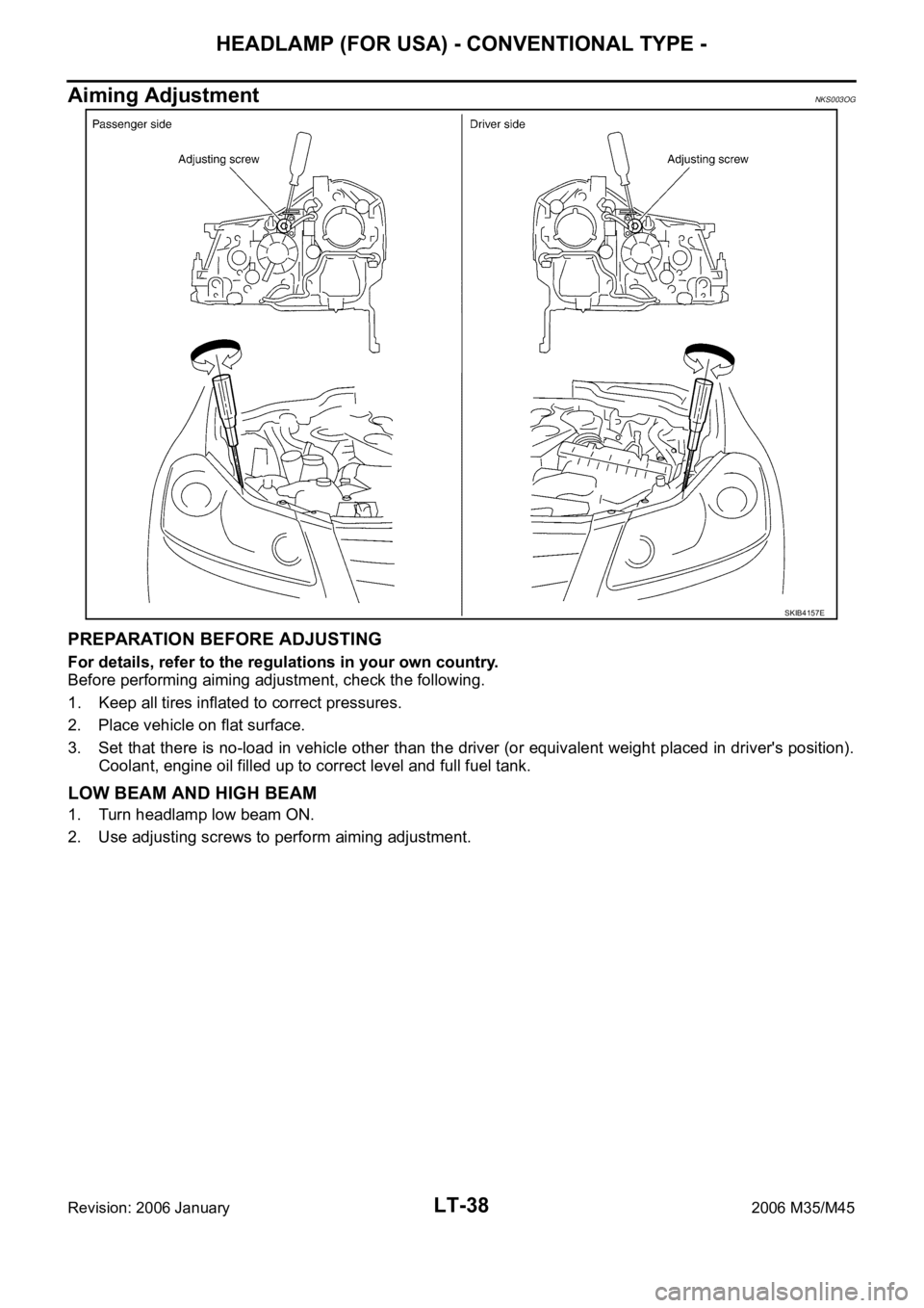
Aiming AdjustmentNKS003OG
PREPARATION BEFORE ADJUSTING
For details, refer to the regulations in your own country.
Before performing aiming adjustment, check the following.
1. Keep all tires inflated to correct pressures.
2. Place vehicle on flat surface.
3. Set that there is no-load in vehicle other than the driver (or equivalent weight placed in driver's position).
Coolant, engine oil filled up to correct level and full fuel tank.
LOW BEAM AND HIGH BEAM
1. Turn headlamp low beam ON.
2. Use adjusting screws to perform aiming adjustment.
SKIB4157E
Page 4501 of 5621

LT-74
HEADLAMP (FOR USA) - XENON TYPE -
Revision: 2006 January2006 M35/M45
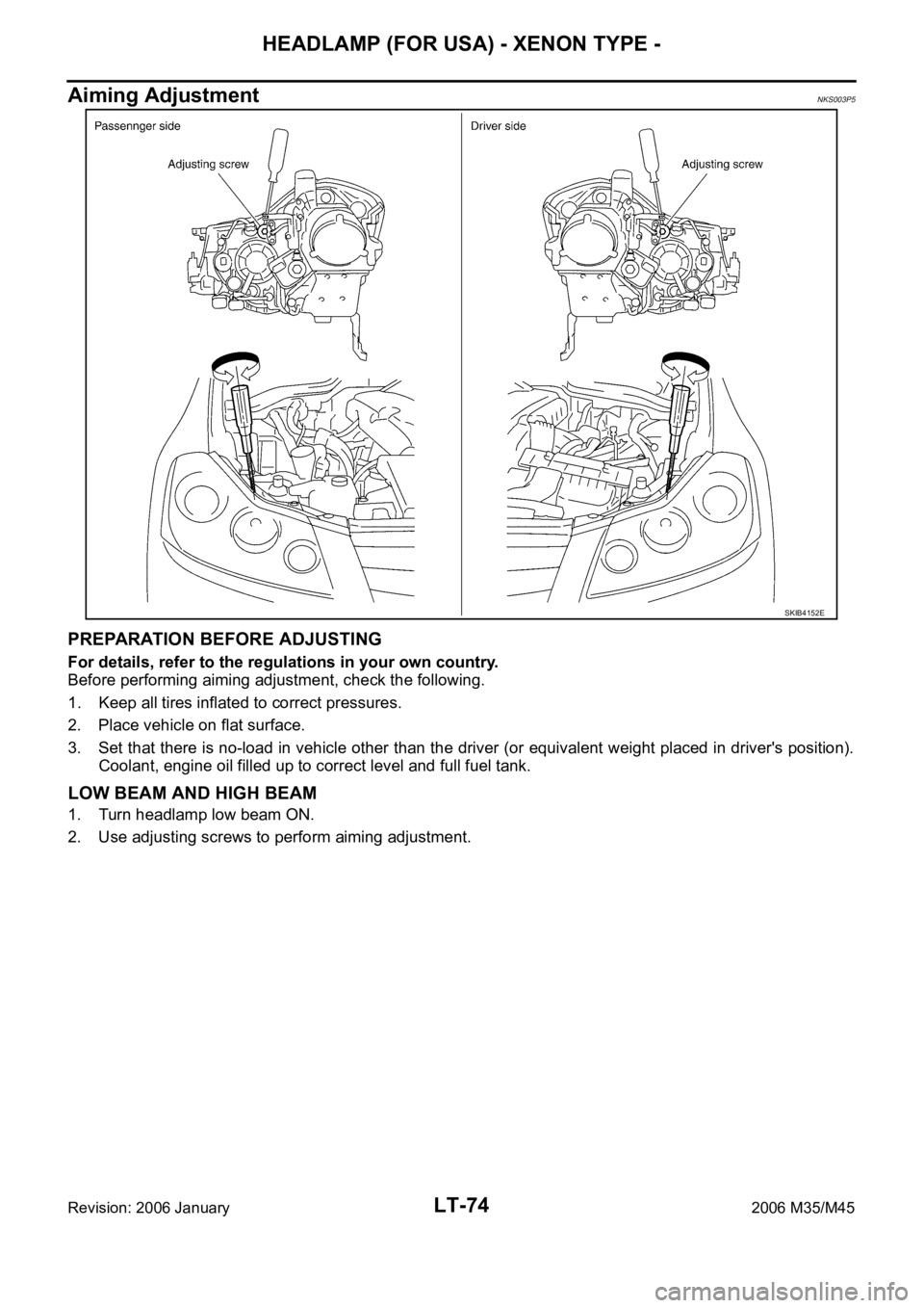
Aiming AdjustmentNKS003P5
PREPARATION BEFORE ADJUSTING
For details, refer to the regulations in your own country.
Before performing aiming adjustment, check the following.
1. Keep all tires inflated to correct pressures.
2. Place vehicle on flat surface.
3. Set that there is no-load in vehicle other than the driver (or equivalent weight placed in driver's position).
Coolant, engine oil filled up to correct level and full fuel tank.
LOW BEAM AND HIGH BEAM
1. Turn headlamp low beam ON.
2. Use adjusting screws to perform aiming adjustment.
SKIB4152E
Page 4750 of 5621
![INFINITI M35 2006 Factory Service Manual ENGINE OIL
LU-7
[VQ35DE]
C
D
E
F
G
H
I
J
K
L
MA
LU
Revision: 2006 January2006 M35/M45
ENGINE OILPFP:KLA92
InspectionNBS004PW
ENGINE OIL LEVEL
NOTE:
Before starting engine, put vehicle horizontally and INFINITI M35 2006 Factory Service Manual ENGINE OIL
LU-7
[VQ35DE]
C
D
E
F
G
H
I
J
K
L
MA
LU
Revision: 2006 January2006 M35/M45
ENGINE OILPFP:KLA92
InspectionNBS004PW
ENGINE OIL LEVEL
NOTE:
Before starting engine, put vehicle horizontally and](/img/42/57023/w960_57023-4749.png)
ENGINE OIL
LU-7
[VQ35DE]
C
D
E
F
G
H
I
J
K
L
MA
LU
Revision: 2006 January2006 M35/M45
ENGINE OILPFP:KLA92
InspectionNBS004PW
ENGINE OIL LEVEL
NOTE:
Before starting engine, put vehicle horizontally and check the engine oil level. If engine is already started, stop
it and allow 10 minutes before checking.
1. Pull out oil level gauge and wipe it clean.
2. Insert oil level gauge and make sure the engine oil level is within
the range shown in the figure.
3. If it is out of range, adjust it.
NOTE:
When checking the engine oil level, insert oil level gauge with its
tip aligned with oil level gauge guide on cylinder head. (In figure,
air cleaner case and air duct are removed.)
ENGINE OIL APPEARANCE
Check engine oil for white turbidity or heavy contamination.
If engine oil becomes turbid and white, it is highly probable that it is contaminated with engine coolant.
Repair or replace damaged parts.
ENGINE OIL LEAKAGE
Check for engine oil leakage around the following areas:
Oil pans (lower and upper)
Oil pan drain plug
Oil pressure switch
Oil filter
Oil filter bracket (AWD models)
Oil cooler
Water pump cover
Chain tensioner cover
Intake valve timing control cover and intake valve timing control solenoid valve
Mating surface between cylinder head and rocker cover
Mating surface between front timing chain case and rear timing chain case
Mating surface between rear timing chain case and cylinder head
Mating surface between rear timing chain case and cylinder block
Mating surface between rear timing chain case and oil pan (upper)
Mating surface between cylinder block and cylinder head
PBIC0249E
KBIA1343E
Page 4751 of 5621
![INFINITI M35 2006 Factory Service Manual LU-8
[VQ35DE]
ENGINE OIL
Revision: 2006 January2006 M35/M45
Crankshaft oil seals (front and rear)
Camshaft position sensor (PHASE)
OIL PRESSURE CHECK
WAR NING :
Be careful not to get burn yourself, as INFINITI M35 2006 Factory Service Manual LU-8
[VQ35DE]
ENGINE OIL
Revision: 2006 January2006 M35/M45
Crankshaft oil seals (front and rear)
Camshaft position sensor (PHASE)
OIL PRESSURE CHECK
WAR NING :
Be careful not to get burn yourself, as](/img/42/57023/w960_57023-4750.png)
LU-8
[VQ35DE]
ENGINE OIL
Revision: 2006 January2006 M35/M45
Crankshaft oil seals (front and rear)
Camshaft position sensor (PHASE)
OIL PRESSURE CHECK
WAR NING :
Be careful not to get burn yourself, as engine oil may be hot.
Oil pressure check should be done in “Parking position”.
1. Check the engine oil level. Refer to LU-7, "
ENGINE OIL LEVEL" .
2. Remove front engine undercover with power tool.
3. Disconnect harness connector at oil pressure switch, and
remove oil pressure switch using deep socket (commercial ser-
vice tool).
CAUTION:
Do not drop or shock oil pressure switch.
Remove the oil pressure switch using a 26 mm (1.02 in) box
wrench. (AWD models)
4. Install the oil pressure gauge (SST) and hose (SST).
5. Start the engine and warm it up to normal operating temperature.
6. Check the engine oil pressure with engine running under no-load.
NOTE:
When the engine oil temperature is low, the engine oil pressure becomes high.
Engine oil pressure [Engine oil temperature at 80
C (176 F)]
If difference is extreme, check engine oil passage and oil pump for engine oil leaks.
7. After the inspections, install oil pressure switch as follows:
SBIA0452E
SBIA0453E
SLC926
Engine speed (rpm)
Approximate discharge pressure [kPa (kg/cm2 , psi)]
Idle speed More than 98 (1.0, 14)
2,000 More than 294 (3.0, 43)
Page 4755 of 5621
![INFINITI M35 2006 Factory Service Manual LU-12
[VQ35DE]
OIL FILTER BRACKET (AWD)
Revision: 2006 January2006 M35/M45
OIL FILTER BRACKET (AWD)PFP:15238
ComponentsNBS004PZ
Refer to GI-11, "Components" for symbol marks in the figure.
Re INFINITI M35 2006 Factory Service Manual LU-12
[VQ35DE]
OIL FILTER BRACKET (AWD)
Revision: 2006 January2006 M35/M45
OIL FILTER BRACKET (AWD)PFP:15238
ComponentsNBS004PZ
Refer to GI-11, "Components" for symbol marks in the figure.
Re](/img/42/57023/w960_57023-4754.png)
LU-12
[VQ35DE]
OIL FILTER BRACKET (AWD)
Revision: 2006 January2006 M35/M45
OIL FILTER BRACKET (AWD)PFP:15238
ComponentsNBS004PZ
Refer to GI-11, "Components" for symbol marks in the figure.
Removal and InstallationNBS004Q0
REMOVAL
WAR NING :
Be careful not to get burn yourself, as engine oil may be hot.
1. Remove front engine undercover with power tool.
2. Using the oil filter wrench [SST: KV10115801 (J38956)], remove oil filter. Refer to LU-10, "
OIL FILTER" .
CAUTION:
Do not spill engine oil on drive belt.
3. Remove connector bolt, and then oil cooler with water hoses connected.
4. Disconnect oil pressure switch harness connectors.
5. Remove oil filter bracket from oil pan (upper).
6. Remove oil pressure switch from oil filter bracket.
INSTALLATION
Note the following, and install in the reverse order of removal.
Install oil pressure switch as follows:
–Remove old liquid gasket adhering to oil filter bracket.
–Apply liquid gasket and install oil pressure switch.
1. Oil filter 2. Connector bolt 3. Oil cooler
4. O-ring 5. Relief valve 6. Oil filter bracket
7. Gasket 8. Oil pressure switch
A. Refer to LU-10
: Engine front
PBIC3393E
Page 4764 of 5621
![INFINITI M35 2006 Factory Service Manual SERVICE DATA AND SPECIFICATIONS (SDS)
LU-21
[VQ35DE]
C
D
E
F
G
H
I
J
K
L
MA
LU
Revision: 2006 January2006 M35/M45
SERVICE DATA AND SPECIFICATIONS (SDS)PFP:00030
Standard and LimitNBS004Q6
ENGINE OIL P INFINITI M35 2006 Factory Service Manual SERVICE DATA AND SPECIFICATIONS (SDS)
LU-21
[VQ35DE]
C
D
E
F
G
H
I
J
K
L
MA
LU
Revision: 2006 January2006 M35/M45
SERVICE DATA AND SPECIFICATIONS (SDS)PFP:00030
Standard and LimitNBS004Q6
ENGINE OIL P](/img/42/57023/w960_57023-4763.png)
SERVICE DATA AND SPECIFICATIONS (SDS)
LU-21
[VQ35DE]
C
D
E
F
G
H
I
J
K
L
MA
LU
Revision: 2006 January2006 M35/M45
SERVICE DATA AND SPECIFICATIONS (SDS)PFP:00030
Standard and LimitNBS004Q6
ENGINE OIL PRESSURE
*: Engine oil temperature at 80C (176F)
ENGINE OIL CAPACITY (APPROXIMATE)
Unit: (US qt, lmp qt)
OIL PUMP
Unit: mm (in)
REGULATOR VALVE
Unit: mm (in) Engine speed (rpm)
Approximate discharge pressure* [kPa (kg/cm
2 , psi)]
Idle speed More than 98 (1.0, 14)
2,000 More than 294 (3.0, 43)
Drain and refill With oil filter change 4.7 (5, 4-1/8)
Without oil filter change 4.4 (4-5/8, 3-7/8)
Dry engine (Overhaul)5.4 (5-3/4, 4-3/4)
Oil pump body to oil pump outer rotor radial clearance 0.114 - 0.260 (0.0045 - 0.0102)
Oil pump inner rotor to oil pump outer rotor tip clearance Below 0.180 (0.0071)
Oil pump body to oil pump inner rotor axial clearance 0.030 - 0.070 (0.0012 - 0.0028)
Oil pump body to oil pump outer rotor axial clearance 0.050 - 0.110 (0.0020 - 0.0043)
Oil pump inner rotor to brazed portion of housing clearance 0.045 - 0.091 (0.0018 - 0.0036)
Regulator valve to oil pump cover clearance 0.040 - 0.097 (0.0016 - 0.0038)
Page 4769 of 5621
![INFINITI M35 2006 Factory Service Manual LU-26
[VK45DE]
ENGINE OIL
Revision: 2006 January2006 M35/M45
ENGINE OILPFP:KLA92
InspectionNBS004QC
ENGINE OIL LEVEL
NOTE:
Before starting engine, put vehicle horizontally and check the engine oil lev INFINITI M35 2006 Factory Service Manual LU-26
[VK45DE]
ENGINE OIL
Revision: 2006 January2006 M35/M45
ENGINE OILPFP:KLA92
InspectionNBS004QC
ENGINE OIL LEVEL
NOTE:
Before starting engine, put vehicle horizontally and check the engine oil lev](/img/42/57023/w960_57023-4768.png)
LU-26
[VK45DE]
ENGINE OIL
Revision: 2006 January2006 M35/M45
ENGINE OILPFP:KLA92
InspectionNBS004QC
ENGINE OIL LEVEL
NOTE:
Before starting engine, put vehicle horizontally and check the engine oil level. If engine is already started, stop
it and allow 15 minutes before checking.
1. Pull out oil level gauge and wipe it clean.
2. Insert oil level gauge and make sure the engine oil level is within
the range shown in the figure.
3. If it is out of range, adjust it.
ENGINE OIL APPEARANCE
Check engine oil for white turbidity or heavy contamination.
If engine oil becomes turbid and white, it is highly probable that it is contaminated with engine coolant.
Repair or replace damaged parts.
ENGINE OIL LEAKAGE
Check for oil leakage around the following area.
Oil pan
Oil pan drain plug
Oil pressure switch
Oil filter
Intake valve timing control cover
Intake valve timing control solenoid valve
Front cover
Chain tensioner cover
Mating surface between cylinder block and cylinder head
Mating surface between cylinder head and rocker cover
Crankshaft oil seals (front and rear)
OIL PRESSURE CHECK
WAR NING :
Be careful not to burn yourself, as engine oil may be hot.
Oil pressure check should be done in “Parking position”.
1. Check the engine oil level. Refer to LU-26, "
ENGINE OIL LEVEL" .
2. Remove front engine undercover with power tool.
3. Disconnect harness connector at oil pressure switch, and
remove oil pressure switch using deep socket (commercial ser-
vice tool).
CAUTION:
Do not drop or shock oil pressure switch.
PBIC0801E
PBIC1524E