wheel INFINITI M35 2006 Factory Service Manual
[x] Cancel search | Manufacturer: INFINITI, Model Year: 2006, Model line: M35, Model: INFINITI M35 2006Pages: 5621, PDF Size: 65.56 MB
Page 3026 of 5621
FENDER PROTECTOR
EI-21
C
D
E
F
G
H
J
K
L
MA
B
EI
Revision: 2006 January2006 M35/M45
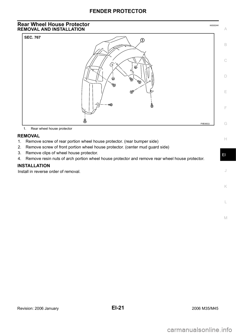
Rear Wheel House ProtectorNIS0024K
REMOVAL AND INSTALLATION
REMOVAL
1. Remove screw of rear portion wheel house protector. (rear bumper side)
2. Remove screw of front portion wheel house protector. (center mud guard side)
3. Remove clips of wheel house protector.
4. Remove resin nuts of arch portion wheel house protector and remove rear wheel house protector.
INSTALLATION
Install in reverse order of removal.
1. Rear wheel house protector
PIIB3602J
Page 3042 of 5621
BODY SIDE TRIM
EI-37
C
D
E
F
G
H
J
K
L
MA
B
EI
Revision: 2006 January2006 M35/M45
BODY SIDE TRIMPFP:76913
Removal and InstallationNIS0024V
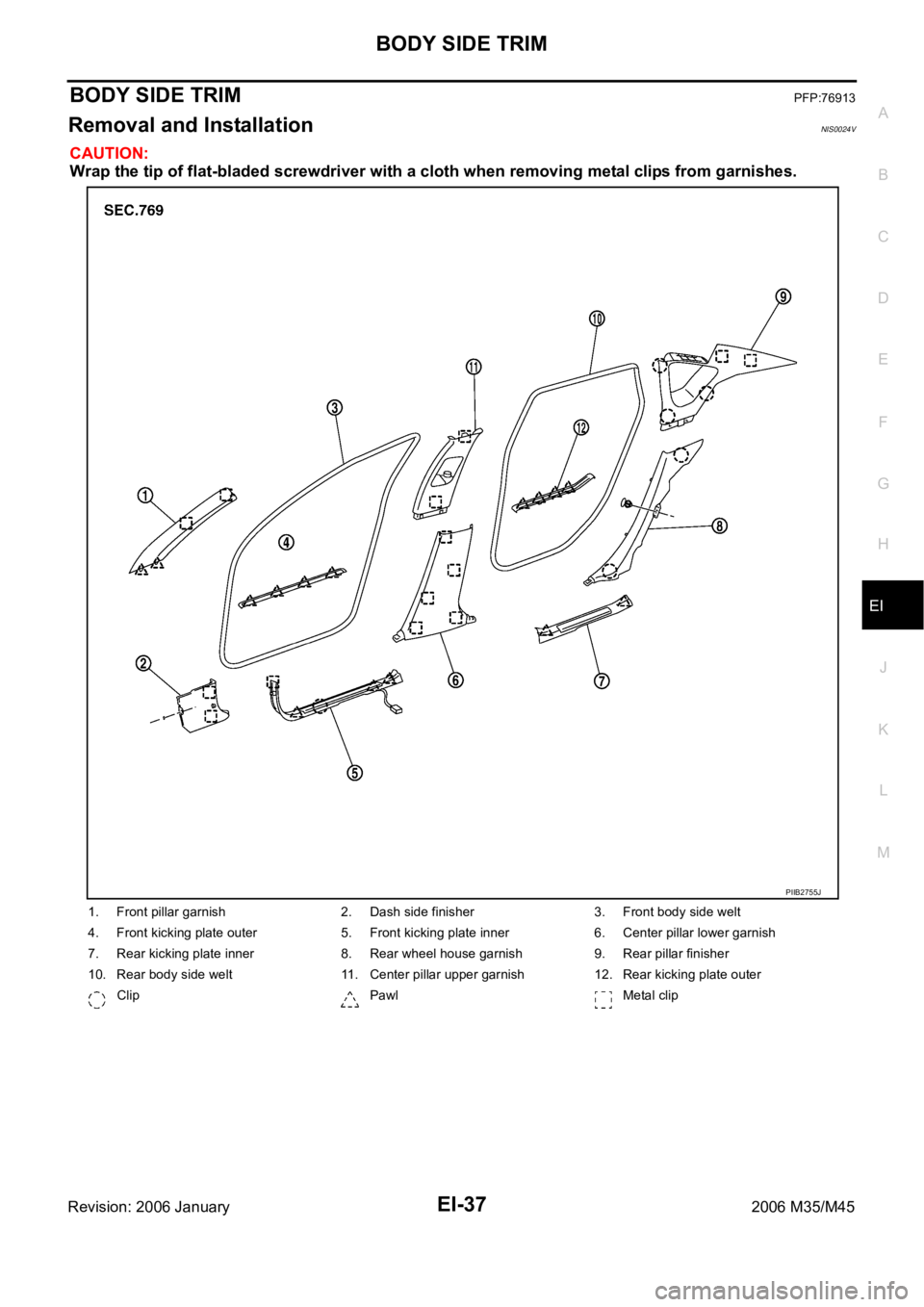
CAUTION:
Wrap the tip of flat-bladed screwdriver with a cloth when removing metal clips from garnishes.
1. Front pillar garnish 2. Dash side finisher 3. Front body side welt
4. Front kicking plate outer 5. Front kicking plate inner 6. Center pillar lower garnish
7. Rear kicking plate inner 8. Rear wheel house garnish 9. Rear pillar finisher
10. Rear body side welt 11. Center pillar upper garnish 12. Rear kicking plate outer
Clip Pawl Metal clip
PIIB2755J
Page 3046 of 5621
BODY SIDE TRIM
EI-41
C
D
E
F
G
H
J
K
L
MA
B
EI
Revision: 2006 January2006 M35/M45
REAR WHEEL HOUSE GARNISH
Removal
1. Remove rear seat cushion and rear seatback. Refer to SE-176, "Removal and Installation" .
2. Remove rear body side welt.
3. Remove clip of rear wheel house garnish.
4. Remove rear wheel house garnish.
Installation
Install in the reverse order of removal.
NOTE:
To install, check if all clips are matched over holes of panel on vehicle, then push on.
REAR PILLAR FINISHER
Removal
1. Remove rear seat cushion and rear seatback. Refer to SE-176, "Removal and Installation" .
2. Remove rear seat belt floor anchor bolt. Refer to SB-32, "
Removal and Installation of Rear Seat Belt" .
3. Remove rear kicking plate inner.
4. Remove rear wheel house garnish.
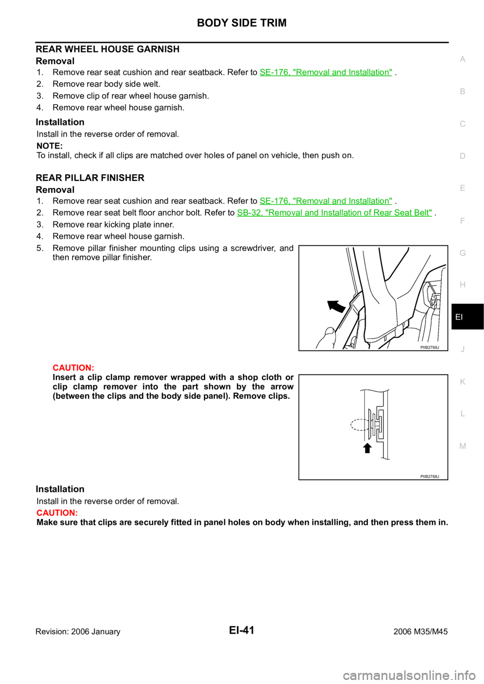
5. Remove pillar finisher mounting clips using a screwdriver, and
then remove pillar finisher.
CAUTION:
Insert a clip clamp remover wrapped with a shop cloth or
clip clamp remover into the part shown by the arrow
(between the clips and the body side panel). Remove clips.
Installation
Install in the reverse order of removal.
CAUTION:
Make sure that clips are securely fitted in panel holes on body when installing, and then press them in.
PIIB2769J
PIIB2768J
Page 3047 of 5621

EI-42
REAR PARCEL SHELF FINISHER
Revision: 2006 January2006 M35/M45
REAR PARCEL SHELF FINISHERPFP:79910
Removal and InstallationNIS0024W
REMOVAL
1. Remove rear seatback and rear seat cushion. Refer to SE-176, "Removal and Installation" .
2. Remove rear seat belt floor anchor bolt and rear seat belt shoulder anchor bolt. Refer to SB-32, "
Removal
and Installation of Rear Seat Belt" .
3. Disengage child anchor cover front pawls, and then pull out child anchor cover (LH/RH center) toward
front of vehicle. (Models with rear window sunshade)
4. Remove rear kicking plate inner, rear wheelhouse garnish, rear pillar finisher. Refer to EI-37, "
BODY SIDE
TRIM" .
1. Rear parcel shelf lid 2. High-mounted stop lamp 3. Child anchor cover
4. Rear parcel shelf finisher 5. Rear seat belt shoulder anchor cover 6. Rear window sunshade
PIIB4590E
Page 3055 of 5621
EI-50
FLOOR TRIM
Revision: 2006 January2006 M35/M45
FLOOR TRIMPFP:74902
Removal and InstallationNIS00252
REMOVAL
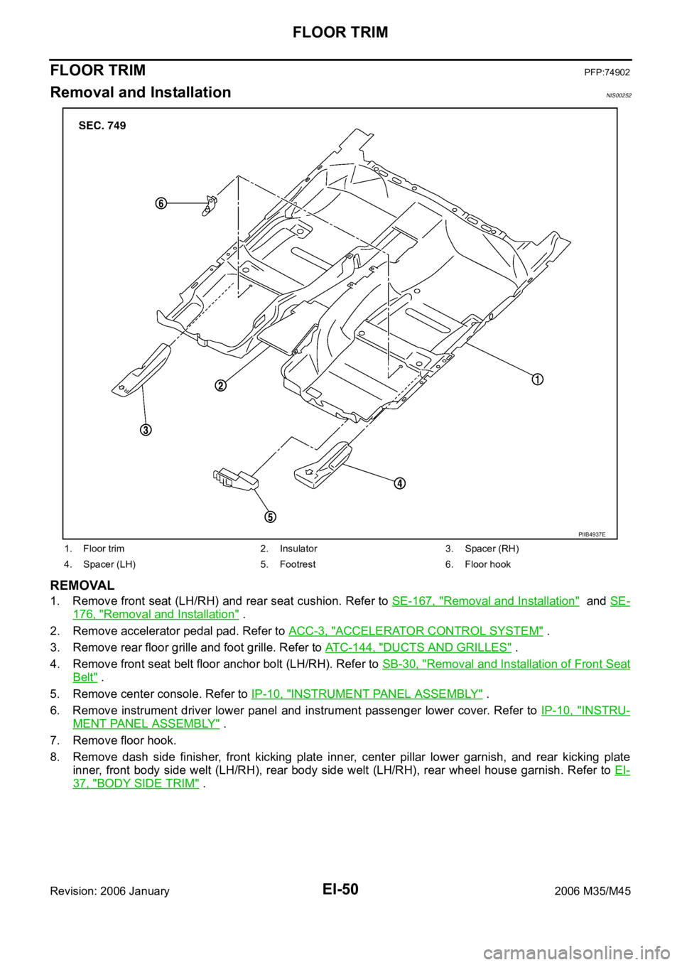
1. Remove front seat (LH/RH) and rear seat cushion. Refer to SE-167, "Removal and Installation" and SE-
176, "Removal and Installation" .
2. Remove accelerator pedal pad. Refer to ACC-3, "
ACCELERATOR CONTROL SYSTEM" .
3. Remove rear floor grille and foot grille. Refer to ATC-144, "
DUCTS AND GRILLES" .
4. Remove front seat belt floor anchor bolt (LH/RH). Refer to SB-30, "
Removal and Installation of Front Seat
Belt" .
5. Remove center console. Refer to IP-10, "
INSTRUMENT PANEL ASSEMBLY" .
6. Remove instrument driver lower panel and instrument passenger lower cover. Refer to IP-10, "
INSTRU-
MENT PANEL ASSEMBLY" .
7. Remove floor hook.
8. Remove dash side finisher, front kicking plate inner, center pillar lower garnish, and rear kicking plate
inner, front body side welt (LH/RH), rear body side welt (LH/RH), rear wheel house garnish. Refer to EI-
37, "BODY SIDE TRIM" .
1. Floor trim 2. Insulator 3. Spacer (RH)
4. Spacer (LH) 5. Footrest 6. Floor hook
PIIB4937E
Page 3058 of 5621
HEADLINING
EI-53
C
D
E
F
G
H
J
K
L
MA
B
EI
Revision: 2006 January2006 M35/M45
REMOVAL
1. Remove front pillar garnish (LH/RH). Refer to EI-37, "BODY SIDE TRIM" .
2. Remove roof harness and antenna feeder securing clip using a clip clamp remover after removing front
pillar garnish (LH/RH), and then disconnect roof harness and antenna feeder connectors.
3. Remove rear seat cushion and seatback. Refer to SE-172, "
REAR SEAT" .
4. Remove front kicking plate inner, center pillar lower garnish, center pillar upper garnish, front body side
welt, rear kicking plate inner, rear wheelhouse garnish, rear pillar finisher, rear body side welt. Refer to EI-
37, "BODY SIDE TRIM" .
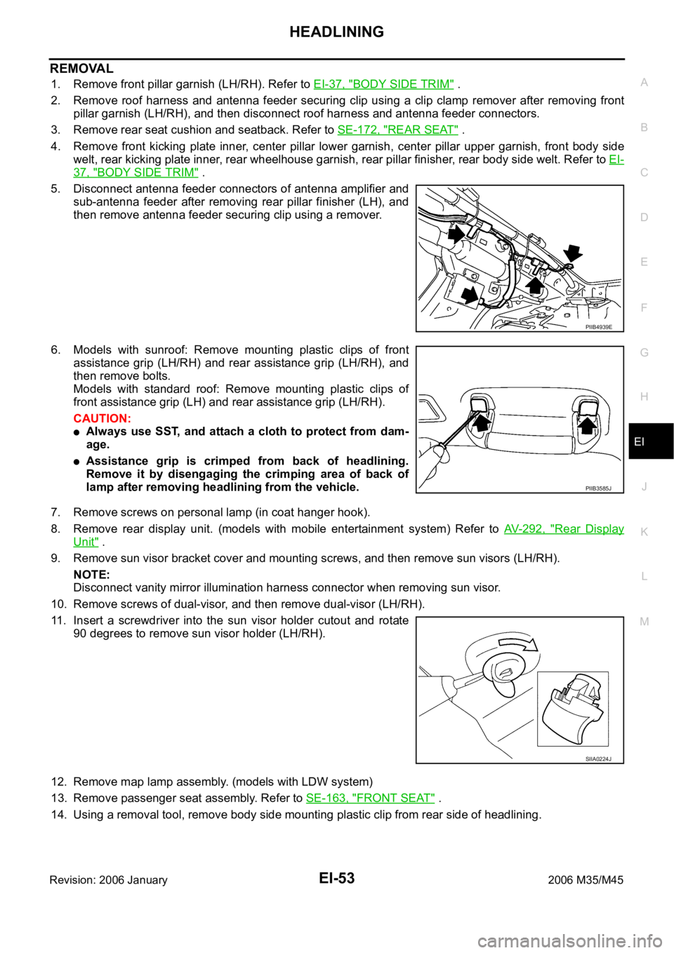
5. Disconnect antenna feeder connectors of antenna amplifier and
sub-antenna feeder after removing rear pillar finisher (LH), and
then remove antenna feeder securing clip using a remover.
6. Models with sunroof: Remove mounting plastic clips of front
assistance grip (LH/RH) and rear assistance grip (LH/RH), and
then remove bolts.
Models with standard roof: Remove mounting plastic clips of
front assistance grip (LH) and rear assistance grip (LH/RH).
CAUTION:
Always use SST, and attach a cloth to protect from dam-
age.
Assistance grip is crimped from back of headlining.
Remove it by disengaging the crimping area of back of
lamp after removing headlining from the vehicle.
7. Remove screws on personal lamp (in coat hanger hook).
8. Remove rear display unit. (models with mobile entertainment system) Refer to AV- 2 9 2 , "
Rear Display
Unit" .
9. Remove sun visor bracket cover and mounting screws, and then remove sun visors (LH/RH).
NOTE:
Disconnect vanity mirror illumination harness connector when removing sun visor.
10. Remove screws of dual-visor, and then remove dual-visor (LH/RH).
11. Insert a screwdriver into the sun visor holder cutout and rotate
90 degrees to remove sun visor holder (LH/RH).
12. Remove map lamp assembly. (models with LDW system)
13. Remove passenger seat assembly. Refer to SE-163, "
FRONT SEAT" .
14. Using a removal tool, remove body side mounting plastic clip from rear side of headlining.
PIIB4939E
PIIB3585J
SIIA0224J
Page 3064 of 5621

EM-1
ENGINE MECHANICAL
B ENGINE
CONTENTS
C
D
E
F
G
H
I
J
K
L
M
SECTION EM
A
EM
Revision: 2006 January2006 M35/M45
ENGINE MECHANICAL
VQ35DE
PRECAUTIONS .......................................................... 5
Precautions for Procedures without Cowl Top Cover ..... 5
Precautions Necessary for Steering Wheel Rotation
After Battery Disconnect .......................................... 5
OPERATION PROCEDURE ................................. 5
Precautions for Drain Engine Coolant and Engine
Oil ............................................................................. 5
Precautions for Disconnecting Fuel Piping .............. 5
Precautions for Removal and Disassembly ............. 5
Precautions for Inspection, Repair and Replace-
ment ......................................................................... 6
Precautions for Assembly and Installation ............... 6
Precautions for Angle Tightening ............................. 6
Precautions for Liquid Gasket .................................. 6
REMOVAL OF LIQUID GASKET SEALING .......... 6
LIQUID GASKET APPLICATION PROCEDURE ..... 7
PREPARATION ........................................................... 8
Special Service Tools ............................................... 8
Commercial Service Tools ...................................... 10
NOISE, VIBRATION AND HARSHNESS (NVH)
TROUBLESHOOTING .............................................. 12
NVH Troubleshooting — Engine Noise .................. 12
Use the Chart Below to Help You Find the Cause
of the Symptom. ..................................................... 13
ENGINE ROOM COVER .......................................... 14
Components ........................................................... 14
Removal and Installation ........................................ 14
REMOVAL ........................................................
... 14
INSTALLATION ................................................... 14
DRIVE BELTS ........................................................... 15
Checking Drive Belts .............................................. 15
Tension Adjustment ................................................ 15
ALTERNATOR AND POWER STEERING OIL
PUMP BELT ........................................................ 16
A/C COMPRESSOR BELT ................................. 16
Removal and Installation ........................................ 16
REMOVAL ........................................................
... 16
INSTALLATION ................................................... 16AIR CLEANER AND AIR DUCT ............................... 17
Components ........................................................... 17
Removal and Installation ........................................ 17
REMOVAL ........................................................
... 17
INSTALLATION ................................................... 17
Changing Air Cleaner Filter .................................... 18
REMOVAL ........................................................
... 18
INSTALLATION ................................................... 18
INTAKE MANIFOLD COLLECTOR .......................... 19
Components ........................................................... 19
Removal and Installation ........................................ 19
REMOVAL ........................................................
... 19
INSPECTION AFTER REMOVAL ....................... 21
INSTALLATION ................................................... 22
INTAKE MANIFOLD ................................................. 24
Components ........................................................... 24
Removal and Installation ........................................ 24
REMOVAL ........................................................
... 24
INSPECTION AFTER REMOVAL ....................... 25
INSTALLATION ................................................... 25
EXHAUST MANIFOLD ............................................. 26
Components ........................................................... 26
Removal and Installation ........................................ 26
REMOVAL ........................................................
... 26
INSPECTION AFTER REMOVAL ....................... 27
INSTALLATION ................................................... 27
OIL PAN AND OIL STRAINER ................................. 29
Components (2WD Models) ................................... 29
Removal and Installation (2WD Models) ................ 29
REMOVAL ........................................................
... 29
INSPECTION AFTER REMOVAL ....................... 31
INSTALLATION ................................................... 31
INSPECTION AFTER INSTALLATION ................ 34
Components (AWD Models) ................................... 35
Removal and Installation (AWD Models) ................ 36
REMOVAL ........................................................
... 36
INSPECTION AFTER REMOVAL ....................... 38
INSTALLATION ................................................... 38
INSPECTION AFTER INSTALLATION ................ 41
Page 3066 of 5621
EM-3
C
D
E
F
G
H
I
J
K
L
M
EMA
Revision: 2006 January2006 M35/M45 ANCE ................................................................146
MAIN BEARING OIL CLEARANCE ..................147
MAIN BEARING CRUSH HEIGHT ....................148
CONNECTING ROD BEARING CRUSH
HEIGHT .............................................................148
MAIN BEARING CAP BOLT OUTER DIAMETER .148
CONNECTING ROD BOLT OUTER DIAMETER .149
DRIVE PLATE ...................................................149
OIL JET .............................................................149
OIL JET RELIEF VALVE ...................................149
SERVICE DATA AND SPECIFICATIONS (SDS) ....150
Standard and Limit ...............................................150
GENERAL SPECIFICATIONS ..........................150
DRIVE BELT .....................................................151
INTAKE MANIFOLD COLLECTOR, INTAKE
MANIFOLD AND EXHAUST MANIFOLD .........151
SPARK PLUG ...................................................151
CAMSHAFT AND CAMSHAFT BEARING ........152
CYLINDER HEAD .............................................154
CYLINDER BLOCK ...........................................157
PISTON, PISTON RING AND PISTON PIN ......158
CONNECTING ROD .........................................159
CRANKSHAFT ..................................................160
MAIN BEARING ................................................161
CONNECTING ROD BEARING ........................162
VK45DE
PRECAUTIONS ......................................................163
Precautions for Procedures without Cowl Top Cover .163
Precautions Necessary for Steering Wheel Rotation
After Battery Disconnect ......................................163
OPERATION PROCEDURE .............................163
Precautions for Drain Engine Coolant and Engine
Oil .........................................................................163
Precautions for Disconnecting Fuel Piping ..........163
Precautions for Removal and Disassembly .........163
Precautions for Inspection, Repair and Replace-
ment .....................................................................164
Precautions for Assembly and Installation ...........164
Parts Requiring Angle Tightening .........................164
Precautions for Liquid Gasket ..............................164
REMOVAL OF LIQUID GASKET SEALING ......164
LIQUID GASKET APPLICATION PROCEDURE .165
PREPARATION .......................................................166
Special Service Tools ...........................................166
Commercial Service Tools ....................................169
NOISE, VIBRATION AND HARSHNESS (NVH)
TROUBLESHOOTING ............................................171
NVH Troubleshooting — Engine Noise ................171
Use the Chart Below to Help You Find the Cause
of the Symptom. ...................................................172
ENGINE ROOM COVER ........................................173
Components .........................................................173
Removal and Installation ......................................173
REMOVAL ........................................................
.173
INSTALLATION .................................................173DRIVE BELTS .........................................................174
Components .........................................................174
Checking Drive Belts ............................................174
Tension Adjustment .............................................
.174
Removal and Installation ......................................174
REMOVAL ........................................................
.174
INSTALLATION .................................................175
Components .........................................................176
Drive Belt Auto Tensioner and Idler Pulley ...........176
REMOVAL ........................................................
.176
INSTALLATION .................................................176
AIR CLEANER AND AIR DUCT .............................177
Components .........................................................177
Removal and Installation ......................................177
REMOVAL ........................................................
.177
INSPECTION AFTER REMOVAL .....................178
INSTALLATION .................................................178
Changing Air Cleaner Filter ..................................178
REMOVAL ........................................................
.178
INSTALLATION .................................................178
INTAKE MANIFOLD ..............................................
.179
Components .........................................................179
Removal and Installation ......................................180
REMOVAL ........................................................
.180
INSPECTION AFTER REMOVAL .....................182
INSTALLATION .................................................182
INSPECTION AFTER INSTALLATION ..............182
EXHAUST MANIFOLD AND THREE WAY CATA-
LYST ........................................................................183
Components .........................................................183
Removal and Installation ......................................183
REMOVAL ........................................................
.183
INSPECTION AFTER REMOVAL .....................185
INSTALLATION .................................................185
OIL PAN AND OIL STRAINER ...............................187
Components .........................................................187
Removal and Installation ......................................187
REMOVAL ........................................................
.187
INSPECTION AFTER REMOVAL .....................188
INSTALLATION .................................................188
INSPECTION AFTER INSTALLATION ..............189
IGNITION COIL .......................................................190
Components .........................................................190
Removal and Installation ......................................190
REMOVAL ........................................................
.190
INSTALLATION .................................................190
SPARK PLUG (PLATINUM-TIPPED TYPE) ...........191
Components .........................................................191
Removal and Installation ......................................191
REMOVAL ........................................................
.191
INSPECTION AFTER REMOVAL .....................191
INSTALLATION .................................................192
FUEL INJECTOR AND FUEL TUBE ......................193
Components .........................................................193
Removal and Installation ......................................193
REMOVAL ........................................................
.193
INSTALLATION .................................................195
INSPECTION AFTER INSTALLATION ..............197
Page 3068 of 5621
![INFINITI M35 2006 Factory Service Manual PRECAUTIONS
EM-5
[VQ35DE]
C
D
E
F
G
H
I
J
K
L
MA
EM
Revision: 2006 January2006 M35/M45
[VQ35DE]PRECAUTIONSPFP:00001
Precautions for Procedures without Cowl Top CoverNBS004MF
When performing the proced INFINITI M35 2006 Factory Service Manual PRECAUTIONS
EM-5
[VQ35DE]
C
D
E
F
G
H
I
J
K
L
MA
EM
Revision: 2006 January2006 M35/M45
[VQ35DE]PRECAUTIONSPFP:00001
Precautions for Procedures without Cowl Top CoverNBS004MF
When performing the proced](/img/42/57023/w960_57023-3067.png)
PRECAUTIONS
EM-5
[VQ35DE]
C
D
E
F
G
H
I
J
K
L
MA
EM
Revision: 2006 January2006 M35/M45
[VQ35DE]PRECAUTIONSPFP:00001
Precautions for Procedures without Cowl Top CoverNBS004MF
When performing the procedure after removing cowl top cover, cover
the lower end of windshield with urethane, etc.
Precautions Necessary for Steering Wheel Rotation After Battery DisconnectNBS005RR
NOTE:
This Procedure is applied only to models with Intelligent Key system and NVIS/IVIS (NISSAN/INFINITI
VEHICLE IMMOBILIZER SYSTEM - NATS).
Remove and install all control units after disconnecting both battery cables with the ignition knob in the
LOCK position.
Always use CONSULT-II to perform self-diagnosis as a part of each function inspection after finishing
work. If DTC is detected, perform trouble diagnosis according to self-diagnostic results.
For models equipped with the Intelligent Key system and NVIS/IVIS, an electrically controlled steering lock
mechanism is adopted on the key cylinder.
For this reason, if the battery is disconnected or if the battery is discharged, the steering wheel will lock and
steering wheel rotation will become impossible.
If steering wheel rotation is required when battery power is interrupted, follow the procedure below before
starting the repair operation.
OPERATION PROCEDURE
1. Connect both battery cables.
NOTE:
Supply power using jumper cables if battery is discharged.
2. Use the Intelligent Key or mechanical key to turn the ignition switch to the
ACC position. At this time, the
steering lock will be released.
3. Disconnect both battery cables. The steering lock will remain released and the steering wheel can be
rotated.
4. Perform the necessary repair operation.
5. When the repair work is completed, return the ignition switch to the
LOCK position before connecting
the battery cables. (At this time, the steering lock mechanism will engage.)
6. Perform a self-diagnosis check of all control units using CONSULT-II.
Precautions for Drain Engine Coolant and Engine OilNBS004MH
Drain engine coolant and engine oil when the engine is cooled.
Precautions for Disconnecting Fuel PipingNBS004MI
Before starting work, make sure no fire or spark producing items are in the work area.
Release fuel pressure before disconnecting and disassembly.
After disconnecting pipes, plug openings to stop fuel leakage.
Precautions for Removal and DisassemblyNBS004MJ
When instructed to use SST, use specified tools. Always be careful to work safely, avoid forceful or unin-
structed operations.
Exercise maximum care to avoid damage to mating or sliding surfaces.
PIIB3706J
Page 3176 of 5621
![INFINITI M35 2006 Factory Service Manual ENGINE ASSEMBLY
EM-113
[VQ35DE]
C
D
E
F
G
H
I
J
K
L
MA
EM
Revision: 2006 January2006 M35/M45
ENGINE ASSEMBLYPFP:10001
Components (2WD Models)NBS004NW
Removal and Installation (2WD Models)NBS004NX
WAR INFINITI M35 2006 Factory Service Manual ENGINE ASSEMBLY
EM-113
[VQ35DE]
C
D
E
F
G
H
I
J
K
L
MA
EM
Revision: 2006 January2006 M35/M45
ENGINE ASSEMBLYPFP:10001
Components (2WD Models)NBS004NW
Removal and Installation (2WD Models)NBS004NX
WAR](/img/42/57023/w960_57023-3175.png)
ENGINE ASSEMBLY
EM-113
[VQ35DE]
C
D
E
F
G
H
I
J
K
L
MA
EM
Revision: 2006 January2006 M35/M45
ENGINE ASSEMBLYPFP:10001
Components (2WD Models)NBS004NW
Removal and Installation (2WD Models)NBS004NX
WAR NING :
Situate the vehicle on a flat and solid surface.
Place chocks at front and back of rear wheels.
For engines not equipped with engine slingers, attach proper slingers and bolts described in
PARTS CATALOG.
CAUTION:
Always be careful to work safely, avoid forceful or uninstructed operations.
Do not start working until exhaust system and engine coolant are cool enough.
If items or work required are not covered by the engine section, refer to the applicable sections.
Always use the support point specified for lifting.
Use either 2-pole lift type or separate type lift as best you can. If board-on type is used for
unavoidable reasons, support at rear axle jacking point with transmission jack or similar tool
before starting work, in preparation for the backward shift of center of gravity.
For supporting points for lifting and jacking point at rear axle, refer to GI-42, "Garage Jack and
Safety Stand and 2-Pole Lift" .
1. Engine mounting bracket (RH) 2. Heat insulator (RH) 3. Engine mounting insulator (RH)
4. Engine mounting bracket (LH) 5. Heat insulator (LH) 6. Engine mounting insulator (LH)
7. Rear engine mounting member 8. Dynamic damper 9. Engine mounting insulator (rear)
10. Dynamic damper
A. Front mark
PBIC3363E