Oil INFINITI M35 2006 Factory Service Manual
[x] Cancel search | Manufacturer: INFINITI, Model Year: 2006, Model line: M35, Model: INFINITI M35 2006Pages: 5621, PDF Size: 65.56 MB
Page 4998 of 5621
SERVICE DATA AND SPECIFICATIONS (SDS)
PS-45
C
D
E
F
H
I
J
K
L
MA
B
PS
Revision: 2006 January2006 M35/M45
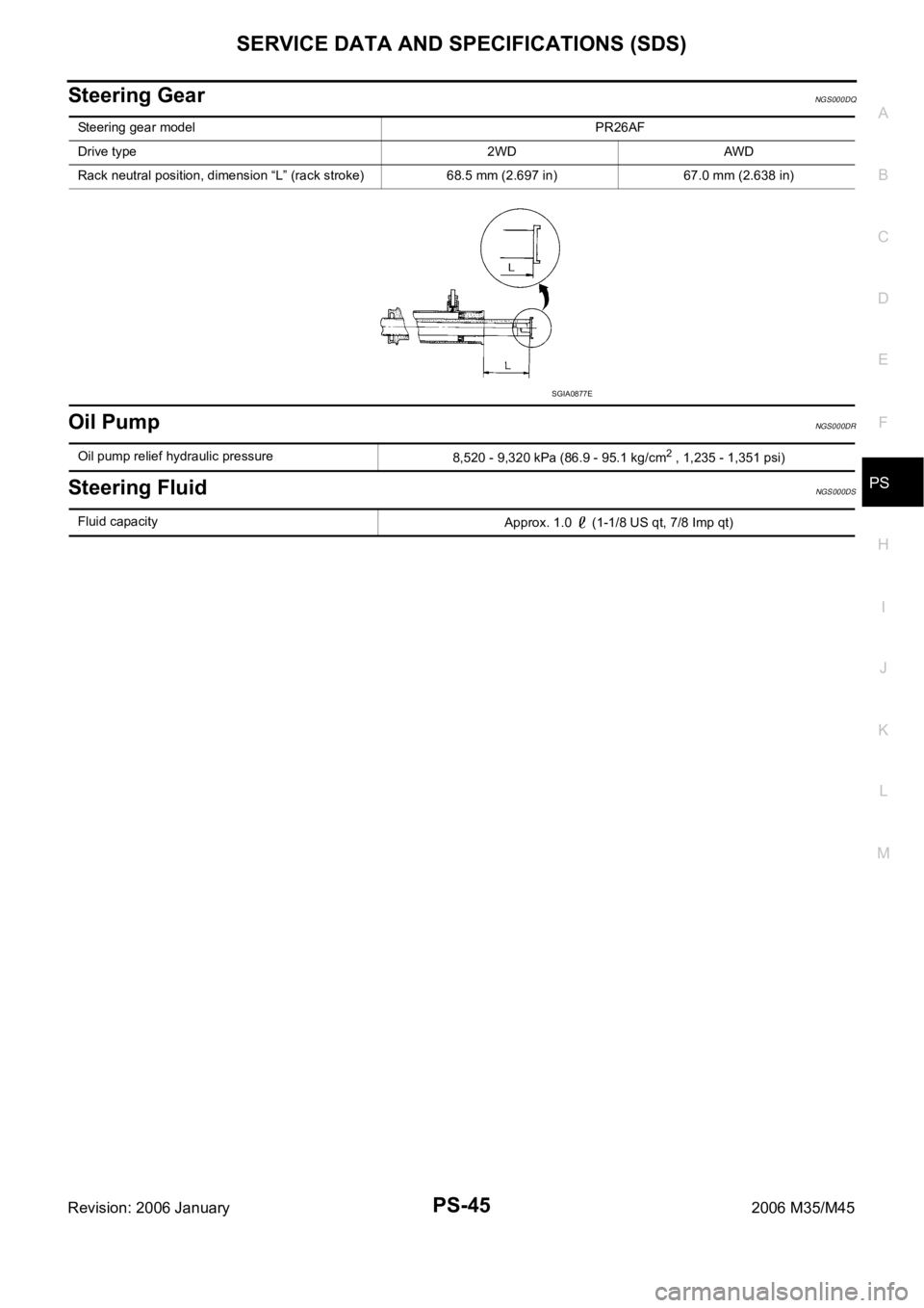
Steering GearNGS000DQ
Oil PumpNGS000DR
Steering FluidNGS000DS
Steering gear model PR26AF
Drive type 2WD AWD
Rack neutral position, dimension “L” (rack stroke) 68.5 mm (2.697 in) 67.0 mm (2.638 in)
SGIA0877E
Oil pump relief hydraulic pressure
8,520 - 9,320 kPa (86.9 - 95.1 kg/cm2 , 1,235 - 1,351 psi)
Fluid capacity
Approx. 1.0 (1-1/8 US qt, 7/8 Imp qt)
Page 5005 of 5621
RAX-6
WHEEL HUB
Revision: 2006 January2006 M35/M45
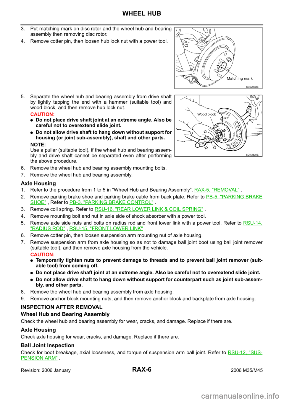
3. Put matching mark on disc rotor and the wheel hub and bearing
assembly then removing disc rotor.
4. Remove cotter pin, then loosen hub lock nut with a power tool.
5. Separate the wheel hub and bearing assembly from drive shaft
by lightly tapping the end with a hammer (suitable tool) and
wood block, and then remove hub lock nut.
CAUTION:
Do not place drive shaft joint at an extreme angle. Also be
careful not to overextend slide joint.
Do not allow drive shaft to hang down without support for
housing (or joint sub-assembly), shaft and other parts.
NOTE:
Use a puller (suitable tool), if the wheel hub and bearing assem-
bly and drive shaft cannot be separated even after performing
the above procedure.
6. Remove the wheel hub and bearing assembly mounting bolts.
7. Remove the wheel hub and bearing assembly.
Axle Housing
1. Refer to the procedure from 1 to 5 in “Wheel Hub and Bearing Assembly”. RAX-5, "REMOVAL" .
2. Remove parking brake shoe and parking brake cable from back plate. Refer to PB-5, "
PA R K I N G B R A K E
SHOE" , Refer to PB-3, "PARKING BRAKE CONTROL" .
3. Remove coil spring. Refer to RSU-16, "
REAR LOWER LINK & COIL SPRING" .
4. Remove mounting bolt and nut in axle side of shock absorber with a power tool.
5. Remove axle side nuts and bolts on radius rod and front lower link with a power tool. Refer to RSU-14,
"RADIUS ROD" , RSU-15, "FRONT LOWER LINK" .
6. Remove cotter pin, then loosen suspension arm mounting nut of axle housing.
7. Remove suspension arm from axle housing so as not to damage ball joint boot using ball joint remover
(suitable tool), and then remove axle housing from the vehicle.
CAUTION:
Temporarily tighten nuts to prevent damage to threads and to prevent ball joint remover (suit-
able tool) from coming off.
Do not place drive shaft joint at an extreme angle. Also be careful not to overextend slide joint.
Do not allow drive shaft to hang down without support for counterpart such as joint sub-assem-
bly, and other parts.
8. Remove the wheel hub and bearing assembly from axle housing.
9. Remove anchor block mounting nuts, and then remove anchor block and backplate from axle housing.
INSPECTION AFTER REMOVAL
Wheel Hub and Bearing Assembly
Check the wheel hub and bearing assembly for wear, cracks, and damage. Replace if there are.
Axle Housing
Check axle housing for wear, cracks, and damage. Replace if there are.
Ball Joint Inspection
Check for boot breakage, axial looseness, and torque of suspension arm ball joint. Refer to RSU-12, "SUS-
PENSION ARM" .
SDIA2638E
SDIA1821E
Page 5015 of 5621

RF-2
PRECAUTIONS
Revision: 2006 January2006 M35/M45
PRECAUTIONSPFP:00001
Precautions for Supplemental Restraint System (SRS) “AIR BAG” and “SEAT
BELT PRE-TENSIONER”
NIS0023J
The Supplemental Restraint System such as “AIR BAG” and “SEAT BELT PRE-TENSIONER”, used along
with a front seat belt, helps to reduce the risk or severity of injury to the driver and front passenger for certain
types of collision. This system includes seat belt switch inputs and dual stage front air bag modules. The SRS
system uses the seat belt switches to determine the front air bag deployment, and may only deploy one front
air bag, depending on the severity of a collision and whether the front occupants are belted or unbelted.
Information necessary to service the system safely is included in the SRS and SB section of this Service Man-
ual.
WAR NING :
To avoid rendering the SRS inoperative, which could increase the risk of personal injury or death
in the event of a collision which would result in air bag inflation, all maintenance must be per-
formed by an authorized NISSAN/INFINITI dealer.
Improper maintenance, including incorrect removal and installation of the SRS, can lead to per-
sonal injury caused by unintentional activation of the system. For removal of Spiral Cable and Air
Bag Module, see the SRS section.
Do not use electrical test equipment on any circuit related to the SRS unless instructed to in this
Service Manual. SRS wiring harnesses can be identified by yellow and/or orange harnesses or
harness connectors.
Precautions NIS0023K
Disconnect both battery cables in advance.
Disconnect air bag system line in advance.
Do not tamper with or force air bag lid open, as this may adversely affect air bag performance.
Be careful not to scratch pad and other parts.
When removing or disassembling any part, be careful not to damage or deform it. Protect parts, which
may get in the way with cloth.
When removing parts with a screwdriver or other tool, protect parts by wrapping them with vinyl or tape.
Keep removed parts protected with cloth.
If a clip is deformed or damaged, replace it.
If an unreusable part is removed, replace it with a new one.
Tighten bolts and nuts firmly to the specified torque.
After re-assembly has been completed, make sure each part functions correctly.
Remove stains in the following way.
Water-soluble stains:
Dip a soft cloth in warm water, and then squeeze it tightly. After wiping the stain, wipe with a soft dry cloth.
Oil stain:
Dissolve a synthetic detergent in warm water (density of 2 to 3% or less), dip the cloth, then clean off the stain
with the cloth. Next, dip the cloth in fresh water and squeeze it tightly. Then clean off the detergent completely.
Then wipe the area with a soft dry cloth.
Do not use any organic solvent, such as thinner or benzine.
Page 5044 of 5621
RFD-1
REAR FINAL DRIVE
D DRIVELINE/AXLE
CONTENTS
C
E
F
G
H
I
J
K
L
M
SECTION RFD
A
B
RFD
Revision: 2006 January2006 M35/M45
REAR FINAL DRIVE
PRECAUTIONS .......................................................... 2
Service Notice or Precautions .................................. 2
PREPARATION ........................................................... 3
Special Service Tools ............................................... 3
Commercial Service Tools ........................................ 6
NOISE, VIBRATION AND HARSHNESS (NVH)
TROUBLESHOOTING ................................................ 7
NVH Troubleshooting Chart ..................................... 7
DESCRIPTION ............................................................ 8
Cross-Sectional View ............................................... 8
DIFFERENTIAL GEAR OIL ........................................ 9
Changing Differential Gear Oil ................................. 9
DRAINING ............................................................. 9
FILLING ................................................................. 9
Checking Differential Gear Oil .................................. 9
OIL LEAKAGE AND OIL LEVEL ........................... 9
FRONT OIL SEAL .................................................
... 10
Removal and Installation ........................................ 10
IDENTIFICATION STAMP OF REPLACEMENT
FREQUENCY OF FRONT OIL SEAL ................. 10
REMOVAL ........................................................
... 10
INSTALLATION ................................................... 12
SIDE OIL SEAL ........................................................ 14
Removal and Installation ........................................ 14
REMOVAL ........................................................
... 14
INSTALLATION ................................................... 14REAR FINAL DRIVE ASSEMBLY ............................ 16
Removal and Installation ........................................ 16
COMPONENTS ................................................... 16
REMOVAL ........................................................
... 16
INSTALLATION ................................................... 17
Disassembly and Assembly .................................... 18
COMPONENTS ................................................... 18
ASSEMBLY INSPECTION AND ADJUSTMENT ... 19
DISASSEMBLY ................................................... 22
INSPECTION AFTER DISASSEMBLY ................ 26
ADJUSTMENT AND SELECTION OF ADJUST-
ING WASHERS ................................................... 26
ASSEMBLY ......................................................... 31
SERVICE DATA AND SPECIFICATIONS (SDS) ...... 37
General Specifications ......................................... ... 37
Inspection and Adjustment ..................................... 37
DRIVE GEAR RUNOUT ...................................... 37
DIFFERENTIAL SIDE GEAR CLEARANCE ....... 37
PRELOAD TORQUE ........................................... 37
BACKLASH ......................................................... 37
COMPANION FLANGE RUNOUT ....................... 37
SELECTIVE PARTS ............................................ 38
Page 5045 of 5621

RFD-2
PRECAUTIONS
Revision: 2006 January2006 M35/M45
PRECAUTIONSPFP:00001
Service Notice or PrecautionsNDS000EY
Check for the correct installation status prior to removal or disassembly. If matching marks are required,
be certain they do not interfere with the function of the parts when applied.
Overhaul should be done in a clean work area, it is preferable to work in dustproof area.
Before disassembly, using steam or white gasoline, completely remove sand and mud from the exterior of
the unit, preventing them from entering into the unit during disassembly or assembly.
Check appearance of the disassembled parts for damage, deformation, and unusual wear. Replace them
with a new ones if necessary.
Gaskets, seals and O-rings should be replaced any time when the unit is disassembled.
In principle, tighten bolts or nuts gradually in several steps working diagonally from inside to outside. If
tightening sequence is specified, observe it.
Clean and flush the parts sufficiently and blow-dry them.
Be careful not to damage sliding surfaces and mating surfaces.
When applying sealant, remove the old sealant from the mounting surface; then remove any moisture, oil,
and foreign materials from the application and mounting surfaces.
Always use shop paper for cleaning the inside of components.
Avoid using cotton gloves or shop rags to prevent entering of lint.
During assembly, observe the specified tightening torque, and apply new gear oil, petroleum jelly, or multi-
purpose grease as specified for each vehicle, if necessary.
Page 5046 of 5621
PREPARATION
RFD-3
C
E
F
G
H
I
J
K
L
MA
B
RFD
Revision: 2006 January2006 M35/M45
PREPARATIONPFP:00002
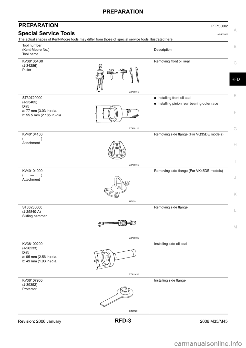
Special Service ToolsNDS000EZ
The actual shapes of Kent-Moore tools may differ from those of special service tools illustrated here.
To o l n u m b e r
(Kent-Moore No.)
To o l n a m eDescription
KV381054S0
(J-34286)
PullerRemoving front oil seal
ST30720000
(J-25405)
Drift
a: 77 mm (3.03 in) dia.
b: 55.5 mm (2.185 in) dia.
Installing front oil seal
Installing pinion rear bearing outer race
KV40104100
(—)
AttachmentRemoving side flange (For VQ35DE models)
KV40101000
(—)
AttachmentRemoving side flange (For VK45DE models)
ST36230000
(J-25840-A)
Sliding hammer Removing side flange
KV38100200
(J-26233)
Drift
a: 65 mm (2.56 in) dia.
b: 49 mm (1.93 in) dia.Installing side oil seal
KV38107900
(J-39352)
ProtectorInstalling side flange
ZZA0601D
ZZA0811D
ZZA0804D
NT159
ZZA0803D
ZZA1143D
S-NT129
Page 5050 of 5621
NOISE, VIBRATION AND HARSHNESS (NVH) TROUBLESHOOTING
RFD-7
C
E
F
G
H
I
J
K
L
MA
B
RFD
Revision: 2006 January2006 M35/M45
NOISE, VIBRATION AND HARSHNESS (NVH) TROUBLESHOOTINGPFP:00003
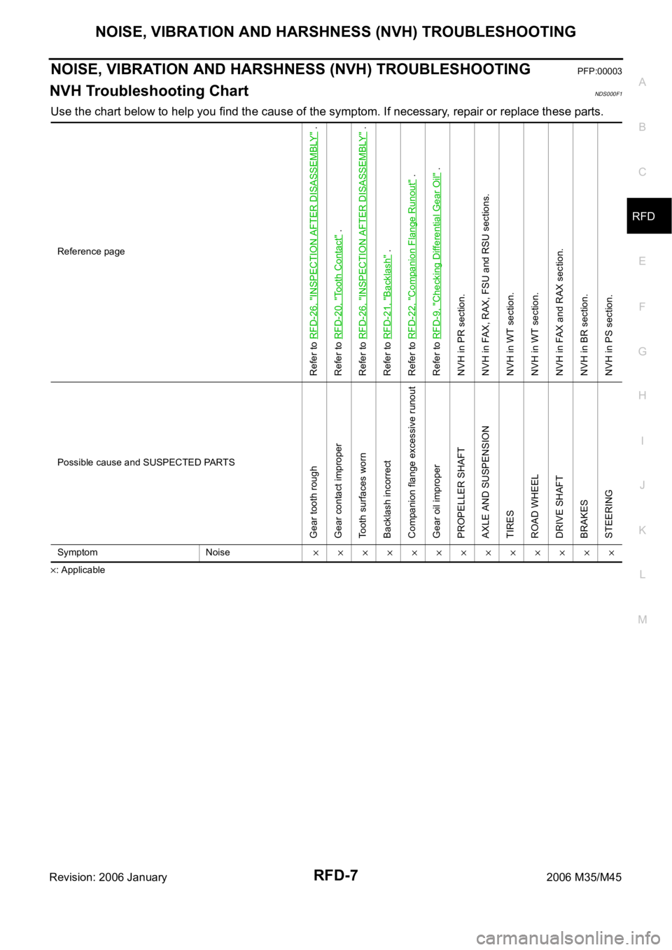
NVH Troubleshooting ChartNDS000F1
Use the chart below to help you find the cause of the symptom. If necessary, repair or replace these parts.
: ApplicableReference page
Refer to RFD-26, "
INSPECTION AFTER DISASSEMBLY
" .
Refer to RFD-20, "
Tooth Contact
" .
Refer to RFD-26, "
INSPECTION AFTER DISASSEMBLY
" .
Refer to RFD-21, "
Backlash
" .
Refer to RFD-22, "
Companion Flange Runout
" .
Refer to RFD-9, "
Checking Differential Gear Oil
" .
NVH in PR section.
NVH in FAX, RAX, FSU and RSU sections.
NVH in WT section.
NVH in WT section.
NVH in FAX and RAX section.
NVH in BR section.
NVH in PS section.
Possible cause and SUSPECTED PARTS
Gear tooth rough
Gear contact improper
Tooth surfaces worn
Backlash incorrect
Companion flange excessive runout
Gear oil improper
PROPELLER SHAFT
AXLE AND SUSPENSION
TIRES
ROAD WHEEL
DRIVE SHAFT
BRAKES
STEERING
Symptom Noise
Page 5052 of 5621
DIFFERENTIAL GEAR OIL
RFD-9
C
E
F
G
H
I
J
K
L
MA
B
RFD
Revision: 2006 January2006 M35/M45
DIFFERENTIAL GEAR OILPFP:KLD30
Changing Differential Gear OilNDS000F3
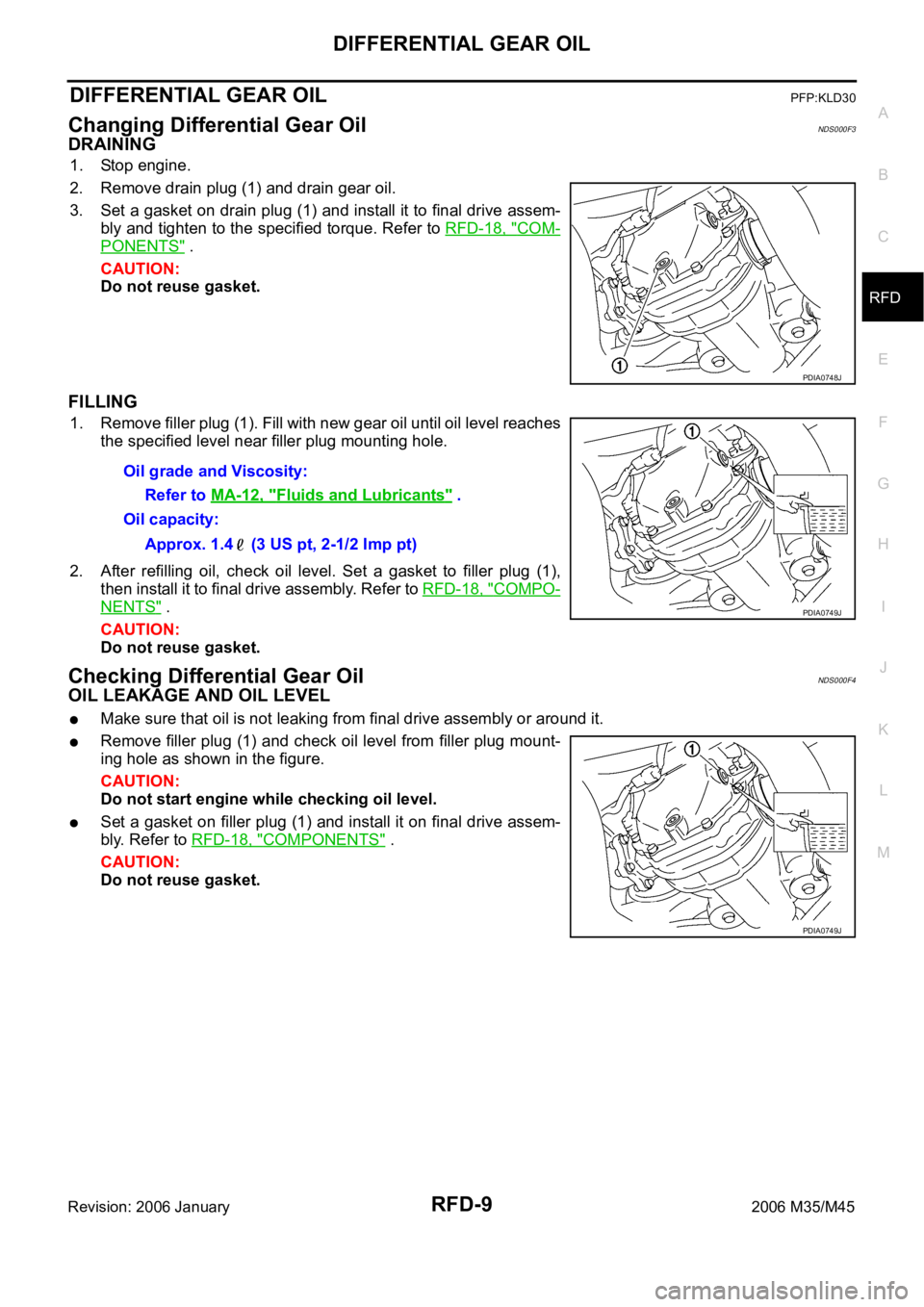
DRAINING
1. Stop engine.
2. Remove drain plug (1) and drain gear oil.
3. Set a gasket on drain plug (1) and install it to final drive assem-
bly and tighten to the specified torque. Refer to RFD-18, "
COM-
PONENTS" .
CAUTION:
Do not reuse gasket.
FILLING
1. Remove filler plug (1). Fill with new gear oil until oil level reaches
the specified level near filler plug mounting hole.
2. After refilling oil, check oil level. Set a gasket to filler plug (1),
then install it to final drive assembly. Refer to RFD-18, "
COMPO-
NENTS" .
CAUTION:
Do not reuse gasket.
Checking Differential Gear OilNDS000F4
OIL LEAKAGE AND OIL LEVEL
Make sure that oil is not leaking from final drive assembly or around it.
Remove filler plug (1) and check oil level from filler plug mount-
ing hole as shown in the figure.
CAUTION:
Do not start engine while checking oil level.
Set a gasket on filler plug (1) and install it on final drive assem-
bly. Refer to RFD-18, "
COMPONENTS" .
CAUTION:
Do not reuse gasket.
PDIA0748J
Oil grade and Viscosity:
Refer to MA-12, "
Fluids and Lubricants" .
Oil capacity:
Approx. 1.4 (3 US pt, 2-1/2 Imp pt)
PDIA0749J
PDIA0749J
Page 5053 of 5621
RFD-10
FRONT OIL SEAL
Revision: 2006 January2006 M35/M45
FRONT OIL SEALPFP:38189
Removal and InstallationNDS000F5
CAUTION:
Verify identification stamp of replacement frequency put in the lower part of gear carrier to determine
replacement for collapsible spacer when replacing front oil seal. Refer to RFD-10, "
IDENTIFICATION
STAMP OF REPLACEMENT FREQUENCY OF FRONT OIL SEAL" . If necessary collapsible spacer
replacement, remove final drive assembly and disassemble it to replace front oil seal and collapsible
spacer. Refer to RFD-16, "
Removal and Installation" and RFD-18, "Disassembly and Assembly" .
NOTE:
The reuse of collapsible spacer is prohibited in principle. However, it is reusable on a one-time basis
only in cases when replacing front oil seal.
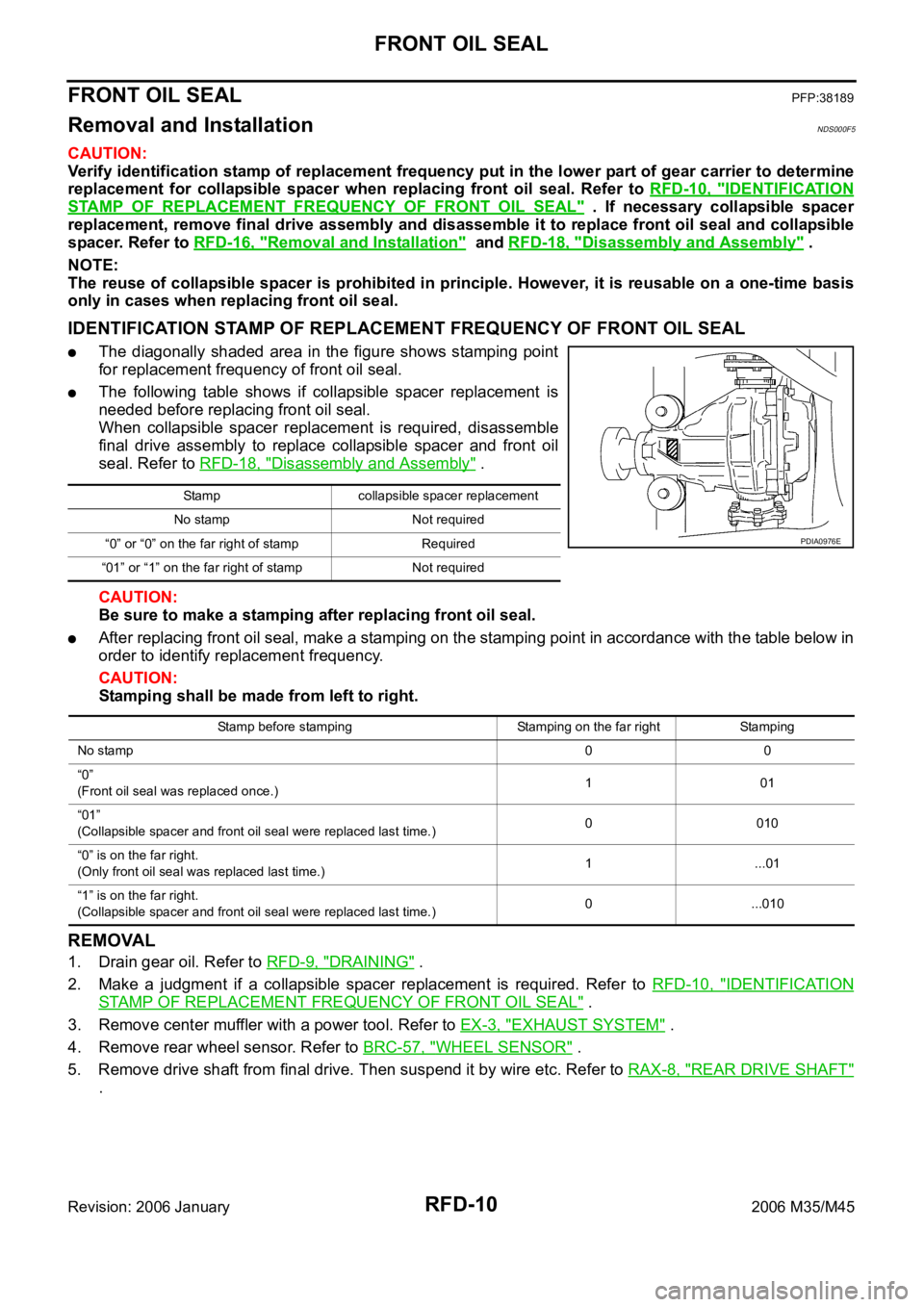
IDENTIFICATION STAMP OF REPLACEMENT FREQUENCY OF FRONT OIL SEAL
The diagonally shaded area in the figure shows stamping point
for replacement frequency of front oil seal.
The following table shows if collapsible spacer replacement is
needed before replacing front oil seal.
When collapsible spacer replacement is required, disassemble
final drive assembly to replace collapsible spacer and front oil
seal. Refer to RFD-18, "
Disassembly and Assembly" .
CAUTION:
Be sure to make a stamping after replacing front oil seal.
After replacing front oil seal, make a stamping on the stamping point in accordance with the table below in
order to identify replacement frequency.
CAUTION:
Stamping shall be made from left to right.
REMOVAL
1. Drain gear oil. Refer to RFD-9, "DRAINING" .
2. Make a judgment if a collapsible spacer replacement is required. Refer to RFD-10, "
IDENTIFICATION
STAMP OF REPLACEMENT FREQUENCY OF FRONT OIL SEAL" .
3. Remove center muffler with a power tool. Refer to EX-3, "
EXHAUST SYSTEM" .
4. Remove rear wheel sensor. Refer to BRC-57, "
WHEEL SENSOR" .
5. Remove drive shaft from final drive. Then suspend it by wire etc. Refer to RAX-8, "
REAR DRIVE SHAFT"
.
Stamp collapsible spacer replacement
No stamp Not required
“0” or “0” on the far right of stamp Required
“01” or “1” on the far right of stamp Not required
PDIA0976E
Stamp before stamping Stamping on the far right Stamping
No stamp00
“0”
(Front oil seal was replaced once.)101
“01”
(Collapsible spacer and front oil seal were replaced last time.)0 010
“0” is on the far right.
(Only front oil seal was replaced last time.)1...01
“1” is on the far right.
(Collapsible spacer and front oil seal were replaced last time.)0 ...010
Page 5054 of 5621
FRONT OIL SEAL
RFD-11
C
E
F
G
H
I
J
K
L
MA
B
RFD
Revision: 2006 January2006 M35/M45
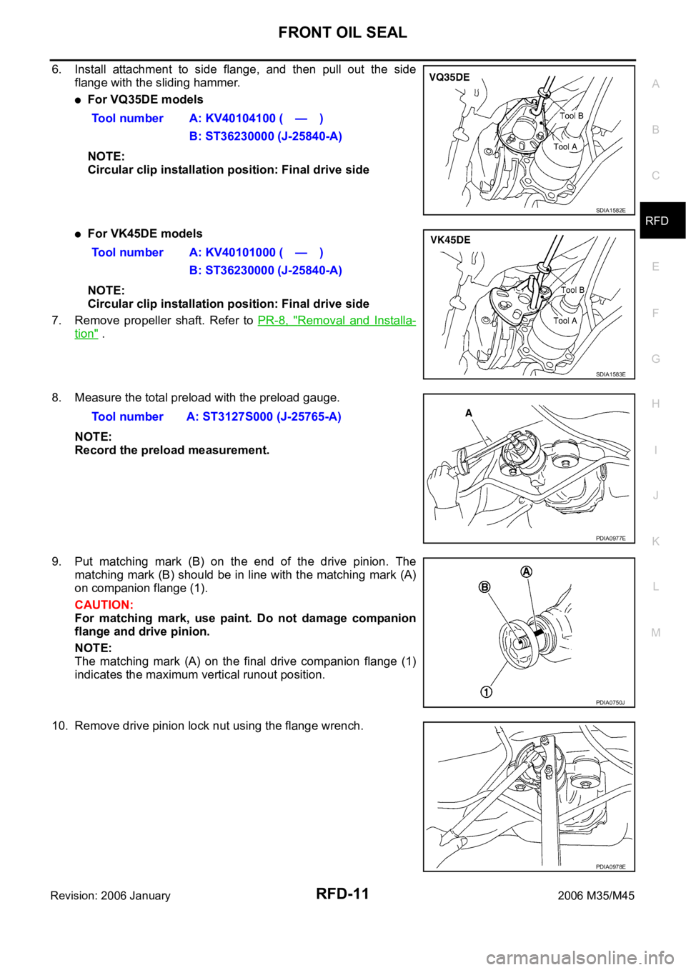
6. Install attachment to side flange, and then pull out the side
flange with the sliding hammer.
For VQ35DE models
NOTE:
Circular clip installation position: Final drive side
For VK45DE models
NOTE:
Circular clip installation position: Final drive side
7. Remove propeller shaft. Refer to PR-8, "
Removal and Installa-
tion" .
8. Measure the total preload with the preload gauge.
NOTE:
Record the preload measurement.
9. Put matching mark (B) on the end of the drive pinion. The
matching mark (B) should be in line with the matching mark (A)
on companion flange (1).
CAUTION:
For matching mark, use paint. Do not damage companion
flange and drive pinion.
NOTE:
The matching mark (A) on the final drive companion flange (1)
indicates the maximum vertical runout position.
10. Remove drive pinion lock nut using the flange wrench.Tool number A: KV40104100 ( — )
B: ST36230000 (J-25840-A)
SDIA1582E
Tool number A: KV40101000 ( — )
B: ST36230000 (J-25840-A)
SDIA1583E
Tool number A: ST3127S000 (J-25765-A)
PDIA0977E
PDIA0750J
PDIA0978E