tow INFINITI Q50 2014 Quick Reference Guide
[x] Cancel search | Manufacturer: INFINITI, Model Year: 2014, Model line: Q50, Model: INFINITI Q50 2014Pages: 24, PDF Size: 1.85 MB
Page 10 of 24

8
Trunk Lid Release
Use one of the following methods to open the trunk:
Push the trunk open request switch
01 for more than
1 second while carrying the INFINITI Intelligent
Key with you.
Press the trunk buttonHOLD on the Intelligent Key for
more than 1 second.
From inside the vehicle, push down on the trunk lid
release switch 02 on the instrument panel.
To completely disable all power to the trunk lid, push
the trunk release power cancel switch
03 to the OFF
position. While in this position, the trunk lid cannot be
opened with the trunk open request switch
01 , trunk
button
HOLD , or the trunk lid release switch
02 until
pushed to the ON position.
For more information, refer to the “Pre-driving checks and adjustments
(section 3)” of your Owner’s Manual.
Seat Adjustments
POWER SEAT ADJUSTMENTS
To slide the seat forward or backward, push the
control switch
01 forward or backward. To recline the seatback, push the switch
02
forward or backward.
SEAT LIFTER
To adjust the angle of the front portion or height of
the seat, push the front or rear end of the switch
01 up or down.
POWER LUMBAR SUPPORT (if so equipped)
To adjust the seat lumbar support, push the front or back end of the swi\
tch 03.
MANUAL LUMBAR SUPPORT (if so equipped)
To adjust the seat lumbar support, move the lever up or down.
SIDE SUPPORT (driver’s seat only) (if so equipped)
The driver’s seat side support adjusts the support on your torso.
Push the switch 04 away from you to loosen the support, or pull the switch
04 toward you
for more support.
MANUAL THIGH EXTENSION (if so equipped)
To slide the thigh extension forward or backward, pull up on the lever 05 under the front of
the seat and slide forward or backward, Release the lever to lock the se\
at in position.
For more information, refer to the “Safety – seats, seat belts and supplemental restraint system (se\
ction 1 )” of your Owner’s Manual.
01
02
03
first drive features
01
04
02
03
05
Page 13 of 24

11
06
light illuminates in the instrument panel.
Pull the headlight switch back to the original
position to select the low beam. The blue
indicator light turns off.
Pull and release the headlight control switch 05 to
flash the headlight high beams on and off.
HIGH BEAM ASSIST (if so equipped)
The high beam assist system will operate when
the vehicle is driven at approximately 22 MPH (35 km/h) and above. If \
an oncoming vehicle
or leading vehicle appears in front of your vehicle when the high beam is on, the headlights
will automatically be switched to the low beam.
Following the procedure below only activates the high beam assist system\
. This does not
necessarily turn on the high beam, even if there is no other traffic. Bo\
th ambient light and
traffic conditions have to be correct for the high beam to illuminate.
To activate high beam assist, turn the headlight control switch to the AUTO position
01 and
push the headlight control switch 04 forward to turn on the high beam. The high beam
assist indicator light will illuminate.
FOG LIGHT SWITCH
The headlights must be on and the low beams selected for the fog lights to operate.
Turn the switch (inside collar) to the
position
06 to turn the fog lights on.
Turn the switch (inside collar)
to the
OFF position to turn the fog lights off.
For more information, refer to the “Instruments and controls (section 2 )” of your Owner’s Manual.
Windshield Wiper and Washer Switch
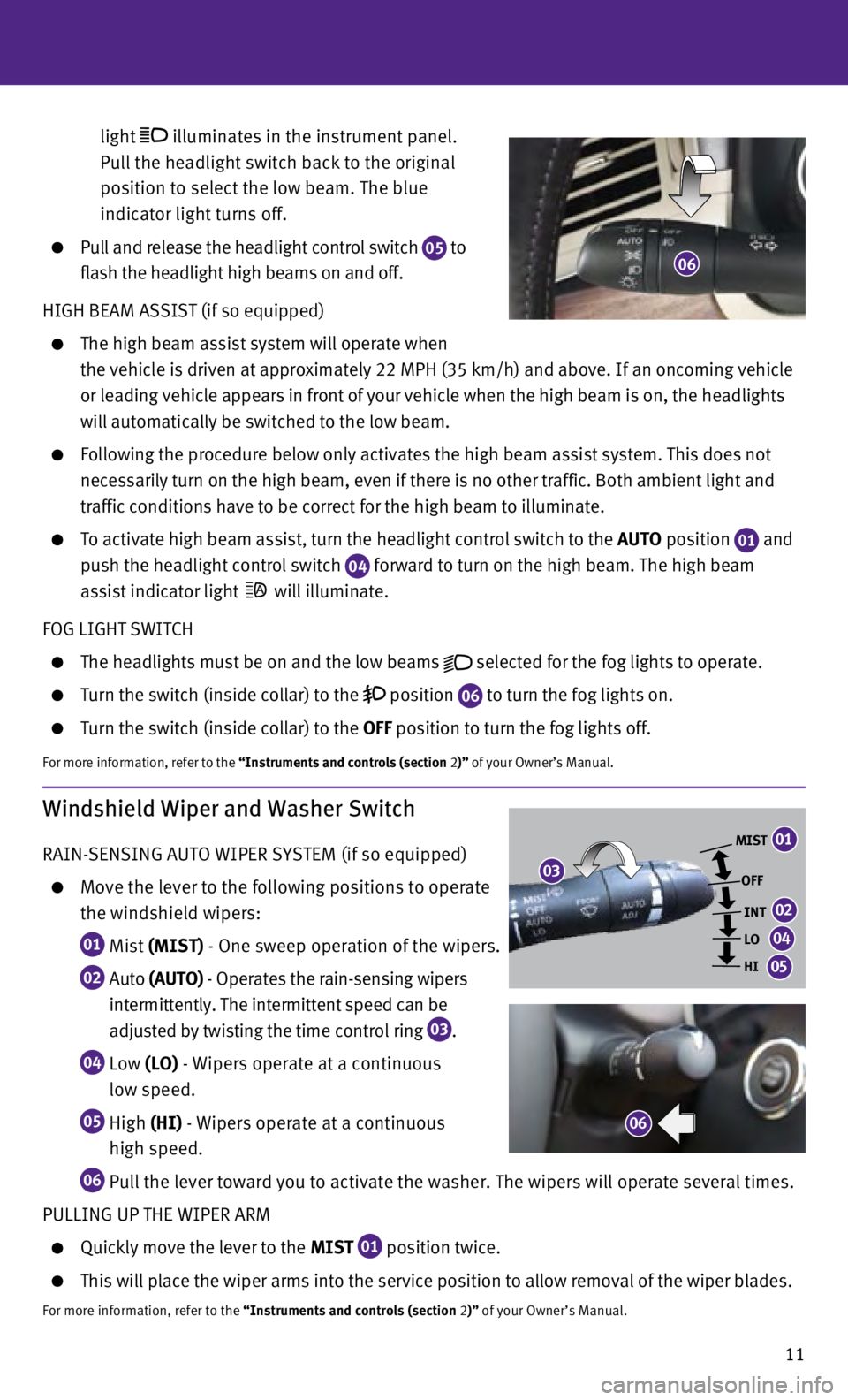
RAIN-SENSING AUTO WIPER SYSTEM (if so equipped)
Move the lever to the following positions to operate
the windshield wipers:
01 Mist (MIST) - One sweep operation of the wipers.
02 Auto (A UTO ) - Operates the rain-sensing wipers
intermittently. The intermittent speed can be
adjusted by twisting the time control ring
03 .
04 Low (LO) - Wipers operate at a continuous
low speed.
05 High (HI) - Wipers operate at a continuous
high speed.
06 Pull the lever toward you to activate the washer. The wipers will operate several times.
PULLING UP THE WIPER ARM
Quickly move the lever to the MIST 01 position twice.
This will place the wiper arms into the service position to allow remova\
l of the wiper blades.
For more information, refer to the “Instruments and controls (section 2)” of your Owner’s Manual.
MIST
OFFINT
LO
HI
06
03
01
02
04
05