INFINITI Q50 2016 Quick Reference Guide
Manufacturer: INFINITI, Model Year: 2016, Model line: Q50, Model: INFINITI Q50 2016Pages: 36, PDF Size: 2.92 MB
Page 11 of 36
9
Scheduled Maintenance Notification – Receive scheduled maintenance no\
tifications
based on mileage data provided by your vehicle.
Maintenance Alert – Receive notification of a vehicle system malfunct\
ion that triggers
instrument panel warning lights.
Destination Assistance – Receive point-of-interest assistance via a g\
uided IVR (Interactive
Voice Response) or a Response Specialist by touching the
key 3
on the map screen or
the Infiniti InTouch Services web portal.
Destination Send-to-Vehicle – Find and download point-of-interest inf\
ormation from
Google Maps™ mapping service.
Connected Search – Select “Connected Search” from the Destinati\
on menu on the
vehicle’s Infiniti InTouch Navigation to conduct a point-of-interest \
search within a certain
distance of the vehicle’s location.
Drive Zone – Monitor the movement of your vehicle within a specified \
region. Set up
boundaries in the Monitoring section of the Infiniti InTouch Services we\
b portal.
Max Speed Alert – Set a maximum speed on the Infiniti InTouch Service\
s web portal. You
will receive notifications if your vehicle exceeds the maximum speed set\
ting.
Mobile Information Service – Receive the latest news headlines, stock\
quotes and sports
scores by setting up preferences on the Mobile Information Service page \
in the Infiniti
InTouch Services web portal.
Valet Alert – Use to set up a 0.2-mile radius around your vehicle.
•
Activate alerts by touching the “Connect to Voice Menu” key on the\
“InTouch Services”
screen or by touching the
key 3 on the map screen.
•
At the prompt, say “Valet Alert” and then “Activate” or “\
Deactivate”.
1 Driving is serious business. Only use services when safe to do so. Servi\
ces, including automatic crash notification and
SOS, require an active subscription and are dependent upon the telematic\
s device being in an operative condition, its
ability to connect to a wireless network, compatible wireless network av\
ailability, navigation map data, and GPS satellite
signal receptions, the absence of which can limit or prevent the ability\
to reach Customer Care or receive support. AT&T
has announced that on December 31, 2016 AT&T will discontinue 2G network\
service. Vehicles equipped with telematics
hardware compatible for use with the 2G GSM/GPRS cellular network provid\
ed by AT&T will be unable to connect to the 2G
network and unable to access the Infiniti InTouch Services features. You\
must enroll by June 30, 2016 to access the services
on the 2G network through December 31, 2016. Services require compatible\
cellular network provided by AT&T. Cellular
network and GPS signal not available in all areas and/or available at al\
l times. Technology is evolving, and changes to cellular
networks provided by independent companies are not within Infiniti’s \
or Sirius XM Connected Vehicle Service’s (“Sirius XM”)
control. Like other devices that rely on network coverage, once the netw\
ork service is discontinued, Infiniti InTouch services
will not function unless equipment replacements, upgrades, or alternativ\
e network coverage are available at that time,
which neither Infiniti nor Sirius XM can guarantee. Infiniti and Sirius \
XM are not responsible for associated costs that may
be required for continued operation due to cellular network turndown or \
discontinuation (including equipment upgrades, if
available, or roaming charges on alternative networks). Certain vehicle\
services and features, including Google
® compatible
services, provided by independent companies are not within Infiniti’s\
or Sirius XM’s control and are subject to change
without notice or liability to Infiniti or Sirius XM and either of their\
affiliates and agents. Text rates and/or data usage may
apply. Certain services require a PIN for activation. See www.infinitius\
a.com/Intouch for more information. App availability
is dependent upon vehicle model, trim level, packaging, and/or options. \
See www.infinitiusa.com/Intouch/system-details
for complete app availability details. Some apps require the Infiniti In\
Touch companion app installed and logged in with an
active account to function. Never program while driving. GPS mapping may\
not be detailed in all areas or reflect current road
status. Compatible smartphone required. Processing speed may vary. May r\
equire retailer service visit or software upgrade to
activate. Terms and conditions of subscription agreement apply.
2 Laws in some communities may restrict the use of text-to-speech. Check \
local regulations before using this feature.
For more information, refer to the “Viewing technical information (section 7)” of your InTouch Owner’s Manual.
1967179_16b_Q50_US_QRG_012916.indd 91/29/16 1:52 PM
Page 12 of 36
10
4
5
6
7
8
first drive features
Infiniti Intelligent Key System
The Infiniti Intelligent Key system allows you to lock or
unlock the vehicle, open the trunk and start the engine.
It is important to make sure the Intelligent Key is with
you (that is, in your pocket or purse).
The operating range of the Intelligent Key is within
31.5 in (80 cm) from each request switch.
LOCKING AND UNLOCKING YOUR VEHICLE
Using the Intelligent Key:
•
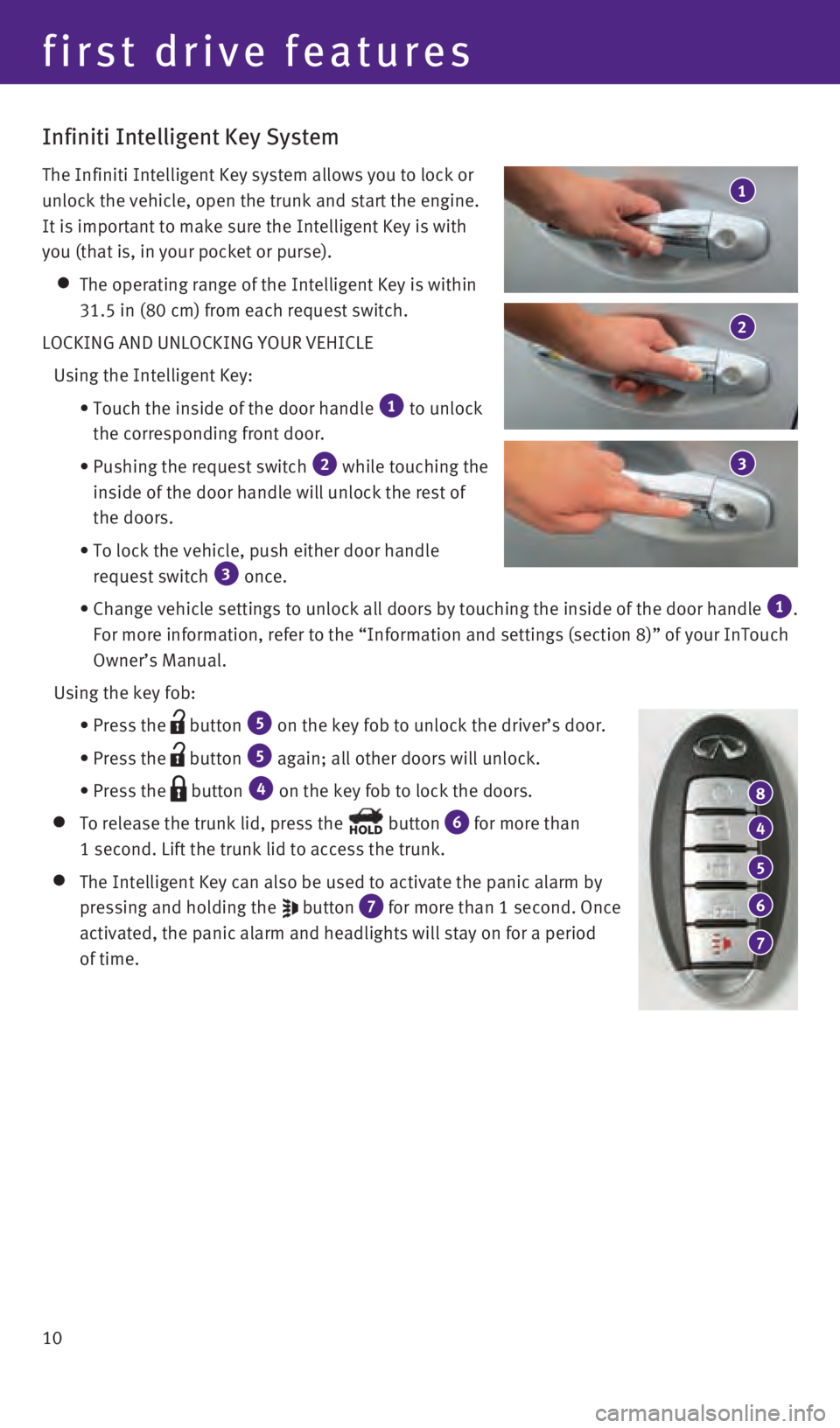
Touch the inside of the door handle 1 to unlock
the corresponding front door.
•
Pushing the request switch 2 while touching the
inside of the door handle will unlock the rest of
the doors.
•
To lock the vehicle, push either door handle
request switch 3 once.
•
Change vehicle settings
to unlock all doors by touching the inside of the door handle
1.
For more information, refer to the “Information and settings (sectio\
n 8)” of your InTouch
Owner’s Manual.
Using the key fob:
•
Press the button 5 on the key fob to unlock the driver’s door.
•
Press the button 5 again; all other doors will unlock.
• Press the button 4 on the key fob to lock the doors.
To release the trunk lid, press the button 6 for more than
1 second. Lift the trunk lid to access the trunk.
The Intelligent Key can also be used to activate the panic alarm by
pressing and holding the
button 7 for more than 1 second. Once
activated, the panic alarm and headlights will stay on for a period
of time.
2
1
3
1967179_16b_Q50_US_QRG_012916.indd 101/29/16 1:52 PM
Page 13 of 36
11
REMOTE ENGINE START* (if so equipped)
The remote engine start system must be enabled in the vehicle settings w\
ithin the
lower display.
The remote engine start operating range is approximately 197 ft (60 m)\
from the vehicle.
The effective operating range may be shorter due to environmental condit\
ions or obstacles
between you and the vehicle.
For the remote engine start to function, the vehicle must be in the P (PARK) position with
the ignition off and all the doors closed and locked.
To start your vehicle remotely:
1.
Press the button 4.
2.
Within 5 seconds, press and hold the remote engine start button 8
for at least 2 seconds.
The engine will start, and the parking lights will turn on.
The automatic climate control system will automatically adjust the passe\
nger compartment
to the appropriate set temperature when the Remote Engine Start feature \
is used.
The engine will run for 10 minutes and then turn off.
Repeat steps 1 and 2 to extend the time for an additional 10-minute peri\
od.
•
After two remote starts, the ignition switch must be cycled before the r\
emote start can be
used again.
To start driving, depress the brake pedal and press the ignition switch \
START/STOP button.
INFINITI INTELLIGENT KEY BATTERY DISCHARGE
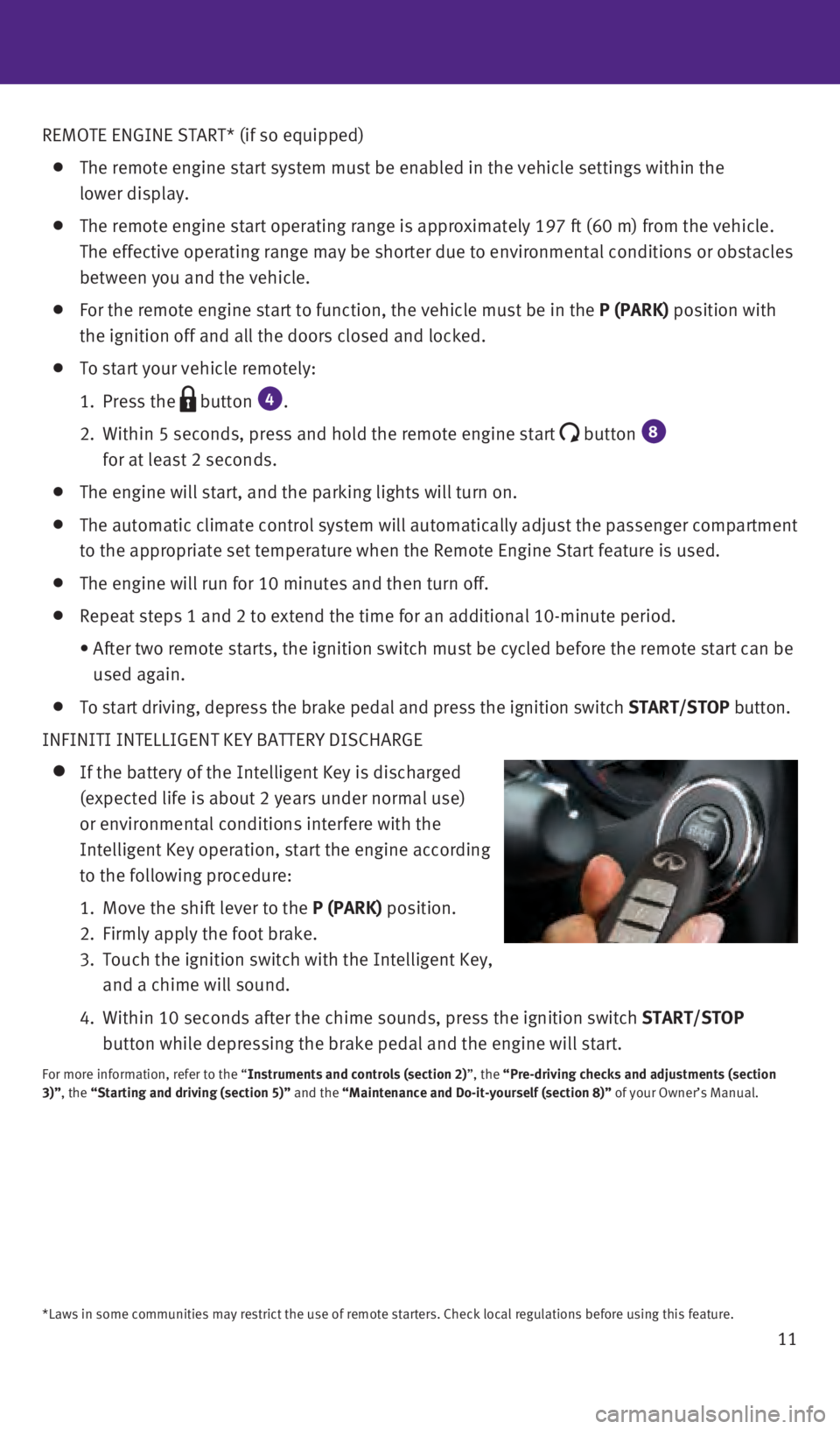
If the battery of the Intelligent Key is discharged
(expected life is about 2 years under normal use)
or environmental conditions interfere with the
Intelligent Key operation, start the engine according
to the following procedure:
1.
Move the shift lever to the
P (PARK) position.
2.
Firmly apply the foot brake.
3.
Touch the ignition switch with the Intelligent Key,
and a chime will sound.
4.
Within 10 seconds after the chime sounds, press the i
gnition switch START/STOP
button while depressing the brake pedal and the engine will start.
For more information, refer to the “Instruments and controls (section 2)”, the “Pre-driving checks and adjustments (section
3)”, the “Starting and driving (section 5)” and the “Maintenance and Do-it-yourself (section 8)” of your Owner’s Manual.
*Laws in some communities may restrict the use of remote starters. Check\
local regulations before using this feature.
1967179_16b_Q50_US_QRG_012916.indd 111/29/16 1:52 PM
Page 14 of 36

12
Around View® Monitor (AVM) with Moving Object Detection (MOD)
(if so equipped)
With the ignition switch in the ON position, the
Around View Monitor is activated by pressing the
CAMERA
button
1, located on the control panel,
or by moving the shift lever to the R (REVERSE)
position. The control panel displays various views
of the position of the vehicle.
When the shift lever is in the P (PARK), N (NEUTRAL)
or D (DRIVE) position and the CAMERA button 1 is
pressed, the following views will display in order:
1
Start from any Control Panel screen
Press
Press Press
Press
Front wide view Front view and bird’s-eye viewFront view and front-side view
When the shift lever is in the
R (REVERSE) position and the CAMERA button 1 is pressed,
the following views will display in order:
Rear view and bird’s-eye view
Press
Press
Press Rear view and front-side view
Rear wide view
first drive features
1967179_16b_Q50_US_QRG_012916.indd 121/29/16 1:53 PM
Page 15 of 36
13
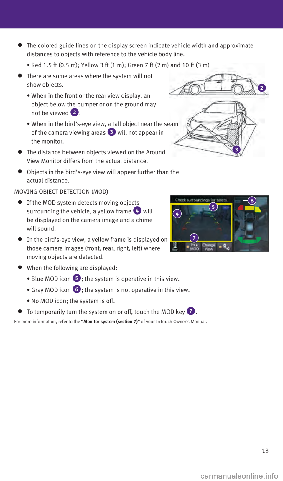
The colored guide lines on the display screen indicate vehicle width and\
approximate
distances to objects with reference to the vehicle body line.
• Red 1.5 ft (0.5 m); Yellow 3 ft (1 m); Green 7 ft (2 m) and 1\
0 ft (3 m)
There are some areas where the system will not
show objects.
•
When in the front or the rear view display, an
object below the bumper or on the ground may
not be viewed
2.
•
When in the bird’s-eye view, a tall object near the seam
of the camera viewing areas 3 will not appear in
the monitor.
The distance between objects viewed on the Around
View Monitor differs from the actual distance.
Objects in the bird’s-eye view will appear further than the
actual distance.
MOVING OBJECT DETECTION (MOD)
If the MOD system detects moving objects
surrounding the vehicle, a yellow frame 4 will
be displayed on the camera image and a chime
will sound.
In the bird’s-eye view, a yellow frame is displayed on
those camera images (front, rear, right, left) where
moving objects are detected.
When the following are displayed:
•
Blue MOD icon 5; the system is operative in this view.
•
Gray MOD icon 6; the system is not operative in this view.
•
No MOD icon; the system is off.
To temporarily turn the system on or off, touch the MOD key 7.
For more information, refer to the “Monitor system (section 7)” of your InTouch Owner’s Manual.
4 5 6
7
3
2
1967179_16b_Q50_US_QRG_012916.indd 131/29/16 1:53 PM
Page 16 of 36
14
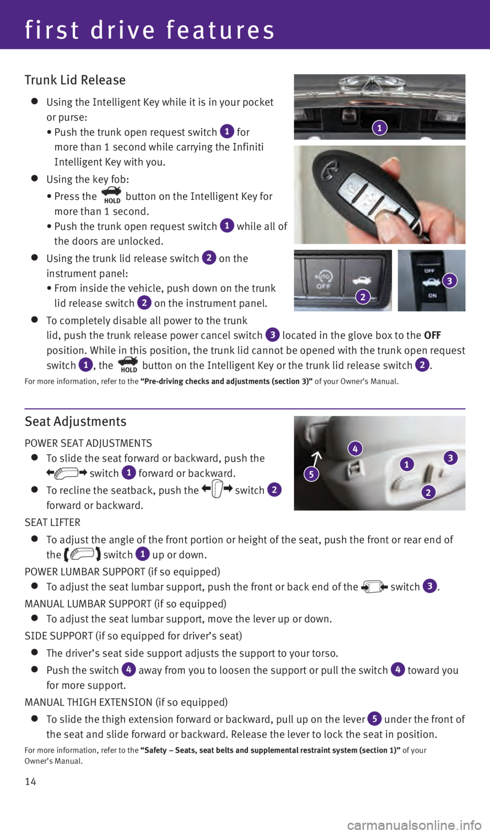
Seat Adjustments
POWER SEAT ADJUSTMENTS
To slide the seat forward or backward, push the
switch 1 forward or backward.
To recline the seatback, push the switch 2
forward or backward.
SEAT LIFTER
To adjust the angle of the front portion or height of the seat, push the\
front or rear end of
the
switch 1 up or down.
POWER LUMBAR SUPPORT (if so equipped)
To adjust the seat lumbar support, push the front or back end of the switch 3.
MANUAL LUMBAR SUPPORT (if so equipped)
To adjust the seat lumbar support, move the lever up or down.
SIDE SUPPORT (if so equipped for driver’s seat)
The driver’s seat side support adjusts the support to your torso.
Push the switch 4 away from you to loosen the support or pull the switch 4 toward you
for more support.
MANUAL THIGH EXTENSION (if so equipped)
To slide the thigh extension forward or backward, pull up on the lever 5 under the front of
the seat and slide forward or backward. Release the lever to lock the se\
at in position.
For more information, refer to the “Safety – Seats, seat belts and supplemental restraint system (se\
ction 1)” of your
Owner’s Manual.
1
4
2
3
5
Trunk Lid Release
Using the Intelligent Key while it is in your pocket
or purse:
•
Push the trunk open request switch 1 for
more than 1 second while carrying the Infiniti
Intelligent Key with you.
Using the key fob:
•
Press the HOLD button on the Intelligent Key for
more than 1 second.
•
Push the trunk open request switch 1 while all of
the doors are unlocked.
Using the trunk lid release switch 2 on the
instrument panel:
•
From inside the vehicle, push down on the trunk
lid release switch
2 on the instrument panel.
To completely disable all power to the trunk
lid, push the trunk release power cancel switch
3 located in the glove box to the OFF
position. While in this position, the trunk lid cannot be opened with th\
e trunk open request
switch
1, the HOLD button on the Intelligent Key or the trunk lid release switch 2.
For more information, refer to the “Pre-driving checks and adjustments (section 3)” of your Owner’s Manual.
1
2
3
first drive features
1967179_16b_Q50_US_QRG_012916.indd 141/29/16 1:53 PM
Page 17 of 36

15
Heated Seats (if so equipped)
There are two ways to operate the heated seats:
1. Push the heated seat switch 1.
•
Every push of the switch allows you to
cycle through the five different modes of
“AUTO”, “High”, “Mid”, “Low” and “OFF”.
2
.
While on the “CLIMATE” screen on the lower
display, touch the left or right heated seat icon
2.
•
The “Left Heater Settings” or “Right Heater
Settings” screen is displayed with a list of the
five different modes of “AUTO”, “High”, “Mid”,
“Low” and “OFF”.
•
The indicator light on the heated seat switch 1
will illuminate when the system is in “AUTO”, “High”, “Mi\
d” or “Low”.
•
While in “AUTO”, the heated seats will turn on and off automatical\
ly depending on
temperature conditions in the vehicle compartment.
•
To view which of the five modes the system is in, press the CLIMATE
button
3. This
will bring up the “CLIMATE” screen on the lower display. From here\
, you will see the
heated seat icons
2 for the driver’s and passenger’s side, and below the icon is the \
mode the system is in currently.
For more information, refer to the “Heater and air conditioner (section 3)” of your InTouch Owner’s Manual.
2 2
3
1 1
Automatic Drive Positioner (if so equipped)
Two positions for the driver’s seat, steering column
and outside mirrors can be stored in the automatic
drive positioner memory.
Follow this procedure to set the memory positions:
•
Confirm the shift lever is in the
P (PARK) position.
•
Adjust the driver’s seat, steering column and
outside mirrors to the desired positions using the adjusting switches fo\
r each feature.
•
Push the
SET switch, and within 5 seconds, push the memory switch (1 or 2) for at
least 1 second.
•
The indicator light on the memory switch you select will illuminate for \
approximately
5 seconds and a buzzer will sound.
•
The driver’s seat, steering column and outside mirror positions are n\
ow set to
your preferences.
For more information, refer to the “Pre-driving checks and adjustments (section 3)” of your Owner’s Manual.
1967179_16b_Q50_US_QRG_012916.indd 151/29/16 1:53 PM
Page 18 of 36
16
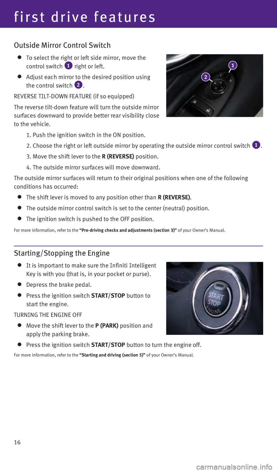
Starting/Stopping the Engine
It is important to make sure the Infiniti Intelligent
Key is with you (that is, in your pocket or purse).
Depress the brake pedal.
Press the ignition switch START/STOP button to
start the engine.
TURNING THE ENGINE OFF
Move the shift lever to the P (PARK) position and
apply the parking brake.
Press the ignition switch START/STOP button to turn the engine off.
For more information, refer to the “Starting and driving (section 5)” of your Owner’s Manual.
Outside Mirror Control Switch
To select the right or left side mirror, move the
control switch 1 right or left.
Adjust each mirror to the desired position using
the control switch 2.
REVERSE TILT-DOWN FEATURE (if so equipped)
The reverse tilt-down feature will turn the outside mirror
surfaces downward to provide better rear visibility close
to the vehicle.
1. Push the ignition switch in the ON position.
2. Choose the right or left outside mirror by operating the outside mirr\
or control switch 1.
3. Move the shift lever to the
R (REVERSE) position.
4. The outside mirror surfaces will move downward.
The outside mirror surfaces will return to their original positions when\
one of the following
conditions has occurred:
The shift lever is moved to any position other than R (REVERSE).
The outside mirror control switch is set to the center (neutral) posit\
ion.
The ignition switch is pushed to the OFF position.
For more information, refer to the “Pre-driving checks and adjustments (section 3)” of your Owner’s Manual.
2
1
first drive features
1967179_16b_Q50_US_QRG_012916.indd 161/29/16 1:53 PM
Page 19 of 36
17
Headlight Control Switch
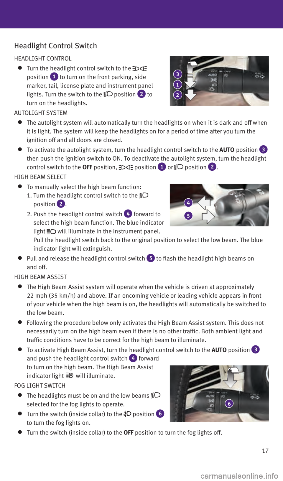
HEADLIGHT CONTROL
Turn the headlight control switch to the
position
1 to turn on the front parking, side
marker, tail, license plate and instrument panel
lights. Turn the switch to the
position 2 to
turn on the headlights.
AUTOLIGHT SYSTEM
The autolight system will automatically turn the headlights on when it i\
s da rk and off when
it is light. The system will keep the headlights on for a period of time\
after you turn the
ignition off and all doors are closed.
To activate the autolight system, turn the headlight control switch to t\
he AUTO position 3
then push the ignition switch to ON. To deactivate the autolight system,\
turn the headlight
control switch to the OFF position,
position 1 or position 2.
HIGH BEAM SELECT
To manually select the high beam function:
1.
Turn the headlight control switch to the
position
2.
2.
Push the headlight control switch 4 forward to
select the high beam function. The blue indicator
light
will illuminate in the instrument panel.
Pull the headlight switch back to the original position to select the lo\
w beam. The blue
indicator light will extinguish.
Pull and release the headlight control switch 5 to flash the headlight high beams on
and off.
HIGH BEAM ASSIST
The High Beam Assist system will operate when the vehicle is driven at a\
pp roximately
22 mph (35 km/h) and above. If an oncoming vehicle or leading vehicle \
appears in front
of your vehicle when the high beam is on, the headlights will automatica\
lly be switched to
the low beam.
Following the procedure below only activates the High Beam Assist system\
. This does not
necessarily turn on the high beam even if there is no other traffic. Bot\
h ambient light and
traffic conditions have to be correct for the high beam to illuminate.
To activate High Beam Assist, turn the headlight control switch to the AUTO position 3
and push the headlight control switch
4 forward
to turn on the high beam. The High Beam Assist
indicator light
will illuminate.
FOG LIGHT SWITCH
The headlights must be on and the low beams
selected for the fog lights to operate.
Turn the switch (inside collar) to the position 6
to turn the fog lights on.
Turn the switch (inside collar) to the OFF position to turn the fog lights off.
6
2
1
3
4
5
1967179_16b_Q50_US_QRG_012916.indd 171/29/16 1:53 PM
Page 20 of 36
18
LANE CHANGE SIGNAL
Move the lever up or down until the turn signal begins to flash but the \
leve
r does not latch
to signal a lane change. Hold the lever until the lane change is complet\
ed.
Move the lever up or down until the turn signal begins to flash but the \
leve r does not latch
and release the lever. The turn signal will automatically flash three ti\
mes.
Choose the appropriate method to signal a lane change based on road and \
traffic conditions.
For more information, refer to the “Instruments and controls (section 2)” of your Owner’s Manual.
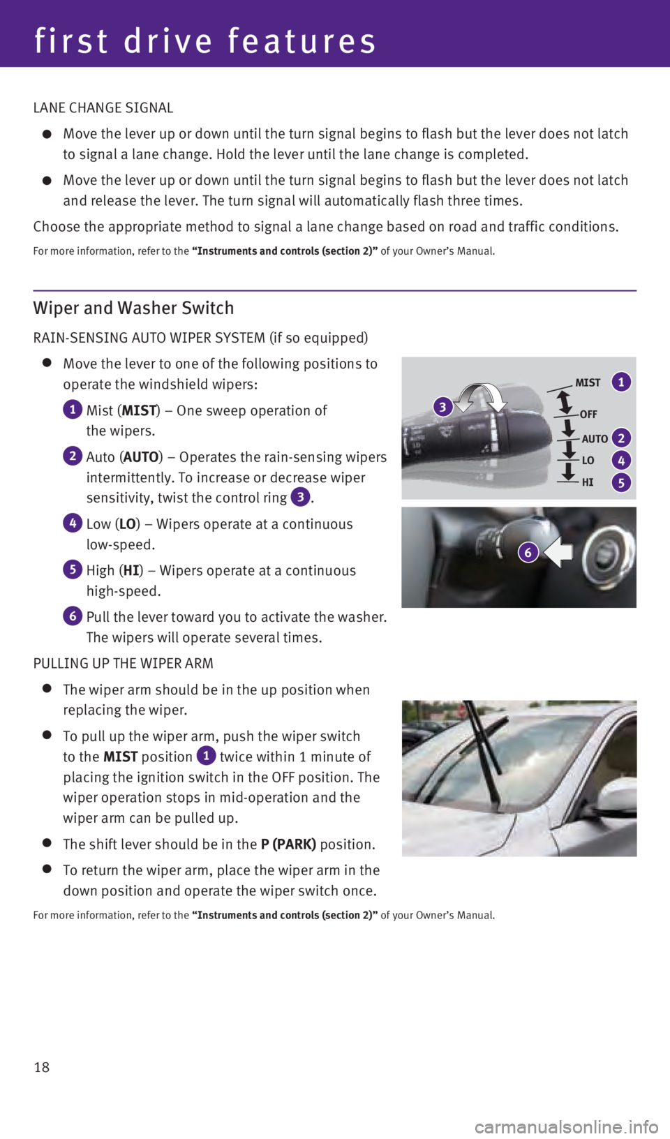
Wiper and Washer Switch
RAIN-SENSING AUTO WIPER SYSTEM (if so equipped)
Move the lever to one of the following positions to
operate the windshield wipers:
1 Mist ( MIST) – One sweep operation of
the wipers.
2 Auto ( AUTO) – Operates the rain-sensing wipers
intermittently. To increase or decrease wiper
sensitivity, twist the control ring
3 .
4 Low ( LO) – Wipers operate at a continuous
low-speed.
5 High ( HI) – Wipers operate at a continuous
high-speed.
6 Pull the lever toward you to activate the washer.
The wipers will operate several times.
PULLING UP THE WIPER ARM
The wiper arm should be in the up position when
replacing the wiper.
To pull up the wiper arm, push the wiper switch
to the MIST position
1 twice within 1 minute of
placing the ignition switch in the OFF position. The
wiper operation stops in mid-operation and the
wiper arm can be pulled up.
The shift lever should be in the P (PARK) position.
To return the wiper arm, place the wiper arm in the
down position and operate the wiper switch once.
For more information, refer to the “Instruments and controls (section 2)” of your Owner’s Manual.
6
MIST
OFFAUTO
LO
HI
3
1
2
4
5
first drive features
1967179_16b_Q50_US_QRG_012916.indd 181/29/16 1:53 PM