tow INFINITI Q50 2018 User Guide
[x] Cancel search | Manufacturer: INFINITI, Model Year: 2018, Model line: Q50, Model: INFINITI Q50 2018Pages: 458, PDF Size: 2.13 MB
Page 120 of 458
SIC3269
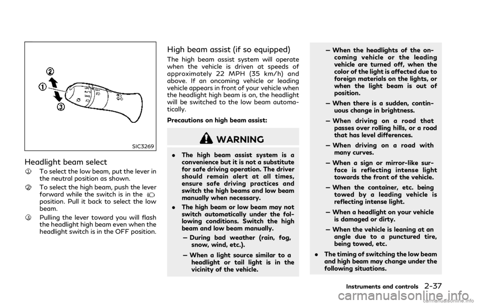
Headlight beam select
To select the low beam, put the lever in
the neutral position as shown.
To select the high beam, push the lever
forward while the switch is in the
position. Pull it back to select the low
beam.
Pulling the lever toward you will flash
the headlight high beam even when the
headlight switch is in the OFF position.
High beam assist (if so equipped)
The high beam assist system will operate
when the vehicle is driven at speeds of
approximately 22 MPH (35 km/h) and
above. If an oncoming vehicle or leading
vehicle appears in front of your vehicle when
the headlight high beam is on, the headlight
will be switched to the low beam automa-
tically.
Precautions on high beam assist:
WARNING
.The high beam assist system is a
convenience but it is not a substitute
for safe driving operation. The driver
should remain alert at all times,
ensure safe driving practices and
switch the high beams and low beam
manually when necessary.
. The high beam or low beam may not
switch automatically under the fol-
lowing conditions. Switch the high
beam and low beam manually.
— During bad weather (rain, fog, snow, wind, etc.).
— When a light source similar to a headlight or tail light is in the
vicinity of the vehicle. — When the headlights of the on-
coming vehicle or the leading
vehicle are turned off, when the
color of the light is affected due to
foreign materials on the lights, or
when the light beam is out of
position.
— When there is a sudden, contin- uous change in brightness.
— When driving on a road that passes over rolling hills, or a road
that has level differences.
— When driving on a road with many curves.
— When a sign or mirror-like sur- face is reflecting intense light
towards the front of the vehicle.
— When the container, etc. being towed by a leading vehicle is
reflecting intense light.
— When a headlight on your vehicle is damaged or dirty.
— When the vehicle is leaning at an angle due to a punctured tire,
being towed, etc.
. The timing of switching the low beam
and high beam may change under the
following situations.
Instruments and controls2-37
Page 123 of 458

2-40Instruments and controls
others.
Adaptive Front lighting System
(AFS) (if so equipped)
The Adaptive Front lighting System (AFS)
will automatically adjust the headlights (low
beam) toward the turning direction to
improve the driver’s view. When the head-
light switch is ON and the driver operates
the steering wheel in a turn, the AFS system
will be activated.
The AFS will operate:
.when the headlight switch is ON.
. when the shift lever is in any position
other than P (Park) or R (Reverse).
. when the vehicle is driven at above 3
MPH (5 km/h) for the left-side head-
light. Note that the right-side low beam
headlight will swivel but the left-side
headlight will not swivel when the vehicle
is below 3 MPH (5 km/h) and the
steering wheel is turned.
AFS will also adjust the headlight to a proper
axis automatically, depending on the number
of occupants in the vehicle, the load the
vehicle is carrying and the road conditions.
If the AFS warning appears in the vehicle
information display after the ignition switch
has been pushed to the ON position, this may indicate that the AFS is not functioning
properly. Have the system checked. It is
recommended you visit an INFINITI retailer
for this service. When the engine is started,
the headlights will vibrate to check the
system condition. This is not a
malfunction.
JVI0644X
JVI0937X
Page 152 of 458
WARNING
.Radio waves could adversely affect
electric medical equipment. Those
who use a pacemaker should contact
the electric medical equipment man-
ufacturer for the possible influences
before use.
. The Intelligent Key transmits radio
waves when the buttons are pushed.
The FAA advises that the radio
waves may affect aircraft navigation
and communication systems. Do not
operate the Intelligent Key while on
an airplane. Make sure the buttons
are not operated unintentionally
when the unit is stored during a
flight.
The Intelligent Key system can operate all
the doors and the trunk lid using the remote
controller function, using one touch unlock
function or pushing the request switch on
the vehicle without taking the key out from a
pocket or purse. The operating environment
and/or conditions may affect the Intelligent
Key system operation.
Be sure to read the following before using
the Intelligent Key system.
CAUTION
. Be sure to carry the Intelligent Key
with you when operating the vehicle.
. Never leave the Intelligent Key in the
vehicle when you leave the vehicle.
The Intelligent Key is always communicating
with the vehicle as it receives radio waves.
The Intelligent Key system transmits weak
radio waves. Environmental conditions may
interfere with the operation of the Intelligent
Key system under the following operating
conditions.
. When operating near a location where
strong radio waves are transmitted, such
as a TV tower, power station and broad-
casting station.
. When in possession of wireless equip-
ment, such as a cellular telephone,
transceiver, and CB radio.
. When the Intelligent Key is in contact
with or covered by metallic materials.
. When any type of radio wave remote
control is used nearby.
. When the Intelligent Key is placed near
an electric appliance such as a personal
computer. .
When the vehicle is parked near a parking
meter.
In such cases, correct the operating condi-
tions before using the Intelligent Key func-
tion or use the mechanical key.
Although the life of the battery varies
depending on the operating conditions, the
battery’s life is approximately 2 years. If the
battery is discharged, replace it with a new
one.
When the Intelligent Key battery is almost
discharged, see “Intelligent Key battery dis-
charge” (P.5-14) to start the engine.
Since the Intelligent Key is continuously
receiving radio waves, if the key is left near
equipment which transmits strong radio
waves, such as signals from a TV and
personal computer, the battery life may
become shorter.
For information regarding replacement of a
battery, see “Intelligent Key battery replace-
ment” (P.8-26).
As many as 4 Intelligent Keys can be
registered and used with one vehicle. For
information about the purchase and use of
additional Intelligent Keys, contact an
INFINITI retailer.
Pre-driving checks and adjustments3-7
INTELLIGENT KEY SYSTEM
Page 166 of 458

Other conditions can affect the performance
of the Intelligent Key transmitter. See “In-
telligent Key system” (P.3-7) for additional
information.
REMOTE ENGINE START OPER-
ATING RANGE
The remote engine start function can only be
used when the Intelligent Key is within the
specified operating range from the vehicle.
When the Intelligent Key battery is dis-
charged or other strong radio wave sources
are present near the operating location, the
Intelligent Key operating range becomes
narrower, and the Intelligent Key may not
function properly.
The remote engine start operating range is
approximately 197 ft (60 m) from the
vehicle.
REMOTE STARTING THE ENGINE
To use the remote start function to start the
engine, perform the following:
1. Aim the Intelligent Key at the vehicle.
2. Push the LOCK
button to lock all
doors.
3. Within 5 seconds push and hold the remote engine start
button until
the turn signal lights flash and the tail
lights illuminate. If the vehicle is not within view, push and hold the remote
engine start
button for at least 2
seconds.
The following events will occur when the
engine starts:
. The front parking lights will turn on and
remain on as long as the engine is
running.
. The doors will be locked and the air
conditioner system may turn on.
. The engine will continue to run for about
10 minutes. Repeat the steps to extend
the time for an additional 10 minutes.
See “Extending engine run time” (P.3-
21).
Depress and hold the brake pedal, then place
the ignition switch in the ON position before
driving. For further instructions, see “Driving
the vehicle” (P.5-16).
EXTENDING ENGINE RUN TIME
The remote engine start function can be
extended one time by performing the steps
listed in “Remote starting the engine” (P.3-
21). Run time will be calculated as follows:
. The first 10 minute run time will start
when the remote engine start function is
performed.
. The second 10 minutes will start imme-
diately when the remote engine start
function is performed. For example, if the engine has been running for 5
minutes, and 10 minutes are added, the
engine will run for a total of 15 minutes.
. Extending engine run time will count
towards the two remote start limit.
A maximum of two remote starts, or a single
start with an extension, are allowed be-
tween ignition cycles.
The ignition switch must be cycled to the ON
position and then back to the OFF position
before the remote engine start procedure
can be used again.
CANCELING A REMOTE START
To cancel a remote start, perform one of the
following:
. Aim the Intelligent Key at the vehicle and
push and hold the remote engine start
button until the parking lights turn
off.
. Turn on the hazard warning flashers.
. Cycle the ignition switch ON and then
OFF.
. The extended engine run time has ex-
pired.
. The first 10 minute timer has expired.
. The engine hood has been opened.
. The shift lever is moved out of P (Park).
. The alarm sounds due to illegal entry into
the vehicle.
Pre-driving checks and adjustments3-21
Page 171 of 458
3-26Pre-driving checks and adjustments
that people become locked inside the trunk
or in the event of the loss of electrical power
such as a discharged battery.
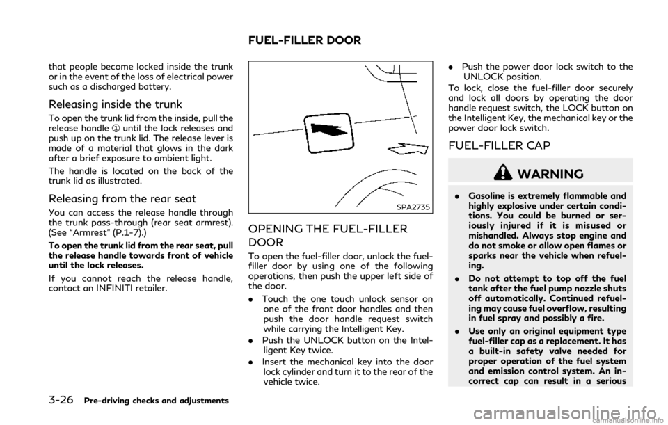
Releasing inside the trunk
To open the trunk lid from the inside, pull the
release handleuntil the lock releases and
push up on the trunk lid. The release lever is
made of a material that glows in the dark
after a brief exposure to ambient light.
The handle is located on the back of the
trunk lid as illustrated.
Releasing from the rear seat
You can access the release handle through
the trunk pass-through (rear seat armrest).
(See “Armrest” (P.1-7).)
To open the trunk lid from the rear seat, pull
the release handle towards front of vehicle
until the lock releases.
If you cannot reach the release handle,
contact an INFINITI retailer.SPA2735
OPENING THE FUEL-FILLER
DOOR
To open the fuel-filler door, unlock the fuel-
filler door by using one of the following
operations, then push the upper left side of
the door.
. Touch the one touch unlock sensor on
one of the front door handles and then
push the door handle request switch
while carrying the Intelligent Key.
. Push the UNLOCK button on the Intel-
ligent Key twice.
. Insert the mechanical key into the door
lock cylinder and turn it to the rear of the
vehicle twice. .
Push the power door lock switch to the
UNLOCK position.
To lock, close the fuel-filler door securely
and lock all doors by operating the door
handle request switch, the LOCK button on
the Intelligent Key, the mechanical key or the
power door lock switch.
FUEL-FILLER CAP
WARNING
. Gasoline is extremely flammable and
highly explosive under certain condi-
tions. You could be burned or ser-
iously injured if it is misused or
mishandled. Always stop engine and
do not smoke or allow open flames or
sparks near the vehicle when refuel-
ing.
. Do not attempt to top off the fuel
tank after the fuel pump nozzle shuts
off automatically. Continued refuel-
ing may cause fuel overflow, resulting
in fuel spray and possibly a fire.
. Use only an original equipment type
fuel-filler cap as a replacement. It has
a built-in safety valve needed for
proper operation of the fuel system
and emission control system. An in-
correct cap can result in a serious
FUEL-FILLER DOOR
Page 177 of 458

3-32Pre-driving checks and adjustments
SPA1829
Foldable outside mirrors
Fold the outside mirror by pushing it toward
the rear of the vehicle.
Reverse tilt-down feature (if so
equipped)
When backing up the vehicle, the right and
left outside mirrors will turn downward
automatically to provide better rear visibility.
1. Push the ignition switch to the ONposition.
2. Move the shift lever to the R (Reverse) position.
3. Select the right or left side mirror by operating the outside mirror control switch.
4. The outside mirror surface moves down- ward.
When one of the following conditions has
occurred, the outside mirror surface will
return to its original position.
. The shift lever is moved to any position
other than R (Reverse).
. The outside mirror control switch is set to
the center position.
. The ignition switch is pushed to the OFF
position.
Automatic anti-glare (if so
equipped)
The outside mirrors are designed so that
they automatically change reflection ac-
cording to the intensity of the headlights of
the vehicle following you.
The anti-glare system will be automatically
turned on when the ignition switch is placed
in the ON position.
SIC3869
VANITY MIRROR
To use the front vanity mirror, pull down the
sun visor and pull up the cover.
Page 188 of 458
THREE-WAY CATALYST
The three-way catalyst is an emission con-
trol device installed in the exhaust system.
Exhaust gases in the three-way catalyst are
burned at high temperatures to help reduce
pollutants.
WARNING
.The exhaust gas and the exhaust
system are very hot. Keep people,
animals or flammable materials away
from the exhaust system compo-
nents.
. Do not stop or park the vehicle over
flammable materials such as dry
grass, waste paper or rags. They
may ignite and cause a fire.
CAUTION
.Do not use leaded gasoline. Deposits
from leaded gasoline seriously reduce
the three-way catalyst’s ability to
help reduce exhaust pollutants.
. Keep your engine tuned up. Malfunc-
tions in the ignition, fuel injection, or
electrical systems can cause overrich fuel flow into the three-way catalyst,
causing it to overheat. Do not keep
driving if the engine misfires, or if
noticeable loss of performance or
other unusual operating conditions
are detected. Have the vehicle in-
spected promptly. It is recommended
you visit an INFINITI retailer for this
service.
. Avoid driving with an extremely low
fuel level. Running out of fuel could
cause the engine to misfire, damaging
the three-way catalyst.
. Do not race the engine while warming
it up.
. Do not push or tow your vehicle to
start the engine.
TIRE PRESSURE MONITORING
SYSTEM (TPMS)
Each tire, including the spare (if provided),
should be checked monthly when cold and
inflated to the inflation pressure recom-
mended by the vehicle manufacturer on the
vehicle placard or tire inflation pressure
label. (If your vehicle has tires of a different
size than the size indicated on the vehicle
placard or tire inflation pressure label, you
should determine the proper tire inflation
pressure for those tires.) As an added safety feature, your vehicle has
been equipped with a Tire Pressure Mon-
itoring System (TPMS) that illuminates a low
tire pressure telltale when one or more of
your tires is significantly under-inflated.
Accordingly, when the low tire pressure
telltale illuminates, you should stop and
check your tires as soon as possible, and
inflate them to the proper pressure. Driving
on a significantly under-inflated tire causes
the tire to overheat and can lead to tire
failure. Under-inflation also reduces fuel
efficiency and tire tread life, and may affect
the vehicle’s handling and stopping ability.
For models with run-flat tires, if the vehicle
is being driven with one or more flat tires,
the low tire pressure warning light will
illuminate continuously and a chime will
sound for 10 seconds. The flat tire warning
will also appear in the vehicle information
display. The chime will only sound at the first
indication of a flat tire, and the warning light
will illuminate continuously. When the flat
tire warning is activated, it is recommended
you have the system reset and the tire
checked and replaced if necessary by an
INFINITI retailer. Even if the tire is inflated
to the specified COLD tire pressure, the
warning light will continue to illuminate until
the system is reset by an INFINITI retailer.
Your vehicle can be driven for a limited time
on a flat tire. See “Run-flat tires” (P.8-39).
Starting and driving5-5
Page 196 of 458

Some indicators and warnings for operation
are displayed in the vehicle information
display between the speedometer and tach-
ometer. (See “Vehicle information display”
(P.2-19).)
The ignition lock is designed so that the
ignition switch position cannot be switched
to LOCK until the shift lever is moved to the
P (Park) position.
When the ignition switch cannot be pushed
toward the LOCK position, proceed as
follows:
1. Move the shift lever into the P (Park)position.
2. Push the ignition switch to the OFF position. The ignition switch position
indicator will not illuminate.
3. Open the door. The ignition switch will change to the LOCK position.
The shift lever can be moved from the P
(Park) position if the ignition switch is in the
ON position and the brake pedal is de-
pressed.PUSH-BUTTON IGNITION
SWITCH POSITIONS
LOCK (Normal parking position)
The ignition switch can only be locked in this
position.
The ignition switch will be unlocked when it
is pushed to the ACC position while carrying
the Intelligent Key.
ACC (Accessories)
This position activates electrical accessories
such as the radio, when the engine is not
running.
ON (Normal operating position)
This position turns on the ignition system
and electrical accessories.
OFF
The engine can be turned off in this position.
The ignition lock is designed so that the
ignition switch cannot be switched to the
LOCK position until the shift lever is moved
to the P (Park) position.
CAUTION
Do not leave the vehicle with the push-
button ignition switch in ACC or ON
positions when the engine is not running
for an extended period. This can dis-
charge the battery.
EMERGENCY ENGINE SHUT OFF
To shut off the engine in an emergency
situation while driving, perform the follow-
ing procedure:
. Rapidly push the push-button ignition
switch 3 consecutive times in less than
1.5 seconds, or
. Push and hold the push-button ignition
switch for more than 2 seconds.
Starting and driving5-13
Page 301 of 458
5-118Starting and driving
JVS0298X
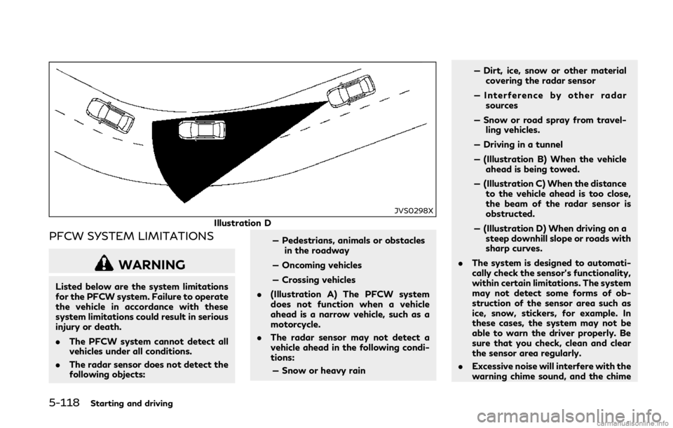
Illustration D
PFCW SYSTEM LIMITATIONS
WARNING
Listed below are the system limitations
for the PFCW system. Failure to operate
the vehicle in accordance with these
system limitations could result in serious
injury or death.
.The PFCW system cannot detect all
vehicles under all conditions.
. The radar sensor does not detect the
following objects: — Pedestrians, animals or obstacles
in the roadway
— Oncoming vehicles
— Crossing vehicles
. (Illustration A) The PFCW system
does not function when a vehicle
ahead is a narrow vehicle, such as a
motorcycle.
. The radar sensor may not detect a
vehicle ahead in the following condi-
tions:
— Snow or heavy rain — Dirt, ice, snow or other material
covering the radar sensor
— Interference by other radar sources
— Snow or road spray from travel- ling vehicles.
— Driving in a tunnel
— (Illustration B) When the vehicle ahead is being towed.
— (Illustration C) When the distance to the vehicle ahead is too close,
the beam of the radar sensor is
obstructed.
— (Illustration D) When driving on a steep downhill slope or roads with
sharp curves.
. The system is designed to automati-
cally check the sensor’s functionality,
within certain limitations. The system
may not detect some forms of ob-
struction of the sensor area such as
ice, snow, stickers, for example. In
these cases, the system may not be
able to warn the driver properly. Be
sure that you check, clean and clear
the sensor area regularly.
. Excessive noise will interfere with the
warning chime sound, and the chime
Page 309 of 458
5-126Starting and driving
SD1006MA
WARNING
.Do not stop or park the vehicle over
flammable materials such as dry
grass, waste paper or rags. They
may ignite and cause a fire.
. Never leave the engine running while
the vehicle is unattended.
. Do not leave children unattended
inside the vehicle. They could un-
knowingly activate switches or con-
trols. Unattended children could
become involved in serious accidents. .
To help avoid risk of injury or death
through unintended operation of the
vehicle and/or its systems, do not
leave children, people who require the
assistance of others or pets unat-
tended in your vehicle. Additionally,
the temperature inside a closed ve-
hicle on a warm day can quickly
become high enough to cause a sig-
nificant risk of injury or death to
people and pets.
. Safe parking procedures require that
both the parking brake be applied
and the transmission placed into P
(Park). Failure to do so could cause the vehicle to move unexpectedly or
roll away and result in an accident.
. Make sure the automatic transmis-
sion shift lever has been pushed as far
forward as it can go and cannot be
moved without depressing the foot
brake pedal.
1. Firmly apply the parking brake.
2. Move the shift lever to the P (Park) position.
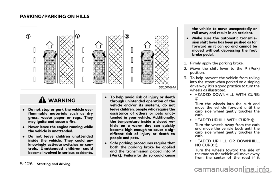
3. To help prevent the vehicle from rolling into the street when parked on a sloping
drive way, it is a good practice to turn the
wheels as illustrated.
.HEADED DOWNHILL WITH CURB:
Turn the wheels into the curb and
move the vehicle forward until the
curb side wheel gently touches the
curb.
.HEADED UPHILL WITH CURB:
Turn the wheels away from the curb
and move the vehicle back until the
curb side wheel gently touches the
curb.
.HEADED UPHILL OR DOWNHILL,
NO CURB:
Turn the wheels toward the side of
the road so the vehicle will move away
from the center of the road if it
PARKING/PARKING ON HILLS