warning lights INFINITI Q50 2019 Owner's Manual
[x] Cancel search | Manufacturer: INFINITI, Model Year: 2019, Model line: Q50, Model: INFINITI Q50 2019Pages: 468, PDF Size: 2.15 MB
Page 237 of 468
![INFINITI Q50 2019 Owners Manual JVS0246X
HOW TO ENABLE/DISABLE THE
BSI SYSTEM
Perform the following steps to enable or
disable the BSI system.
1. Push the MENU button
and touch
[Driver Assistance] on the lower display.
2. Touch [Bli INFINITI Q50 2019 Owners Manual JVS0246X
HOW TO ENABLE/DISABLE THE
BSI SYSTEM
Perform the following steps to enable or
disable the BSI system.
1. Push the MENU button
and touch
[Driver Assistance] on the lower display.
2. Touch [Bli](/img/42/41085/w960_41085-236.png)
JVS0246X
HOW TO ENABLE/DISABLE THE
BSI SYSTEM
Perform the following steps to enable or
disable the BSI system.
1. Push the MENU button
and touch
[Driver Assistance] on the lower display.
2. Touch [Blind Spot Assist].
3. Touch [Blind Spot Intervention] to en- able or disable the system.
Setting the side indicator light
brightness
The brightness of the side indicator lights
can be changed using the following steps: 1. Push the MENU button
and touch
[Driver Assistance] on the lower display.
2. Touch [Blind Spot Assist].
3. Touch [+] or [-] in [Side Indicator Bright- ness] to select [Bright], [Standard] or
[Dark].
When the brightness setting is changed, the
side indicator lights illuminate for a few
seconds.
BSI SYSTEM LIMITATIONS
WARNING
Listed below are the system limitations
for the BSI system. Failure to operate
the vehicle in accordance with these
system limitations could result in serious
injury or death.
. The BSI system cannot detect all
vehicles under all conditions.
. The radar sensors may not be able to
detect and activate BSI when certain
objects are present such as:
— Pedestrians, bicycles, animals.
— Vehicles such as motorcycles, low height vehicles, or high ground
clearance vehicles. — Vehicles remaining in the detec-
tion zone when you accelerate
from a stop.
— Oncoming vehicles.
— A vehicle merging into an adja- cent lane at a speed approxi-
mately the same as your vehicle.
— A vehicle approaching rapidly from behind.
— A vehicle which your vehicle over- takes rapidly.
— A vehicle that passes through the detection zone quickly.
. The radar sensor’s detection zone is
designed based on a standard lane
width. When driving in a wider lane,
the radar sensors may not detect
vehicles in an adjacent lane. When
driving in a narrow lane, the radar
sensors may detect vehicles driving
two lanes away.
. The radar sensors are designed to
ignore most stationary objects, how-
ever objects such as guardrails, walls,
foliage and parked vehicles may oc-
casionally be detected. This is a
normal operation condition.
. The camera may not detect lane
markers in the following situations
Starting and driving5-53
Page 265 of 468

A warning chime will sound and the “cur-
rently unavailable” warning message ap-
pears in the vehicle information display.
.When the INFINITI Drive Mode Selector
is turned to the SNOW mode (To use the
ICC system, turn the INFINITI Drive
Mode Selector to a mode other than
the SNOW mode, push the MAIN switch
to turn off the ICC and reset the ICC
switch by pressing the MAIN switch
again.)
For details about the INFINITI Drive
Mode Selector, see “INFINITI Drive
Mode Selector” (P.5-22).
. When the VDC system is off (To use the
ICC system, turn on the VDC system.
Push the MAIN switch to turn off the
ICC system and reset the ICC switch by
pushing the MAIN switch again.)
For details about the VDC system, see
“Vehicle Dynamic Control (VDC) system”
(P.5-133).
. When ABS or VDC (including the traction
control system) is operating
. When a wheel is slipping (To use the ICC
system, make sure the wheels are no
longer slipping.)
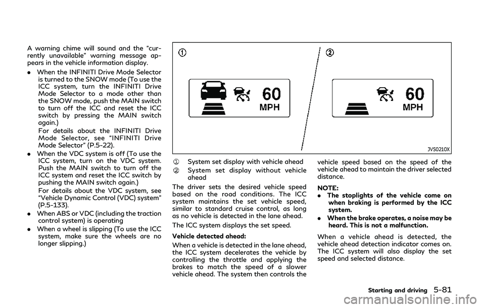
JVS0210X
System set display with vehicle ahead
System set display without vehicle
ahead
The driver sets the desired vehicle speed
based on the road conditions. The ICC
system maintains the set vehicle speed,
similar to standard cruise control, as long
as no vehicle is detected in the lane ahead.
The ICC system displays the set speed.
Vehicle detected ahead:
When a vehicle is detected in the lane ahead,
the ICC system decelerates the vehicle by
controlling the throttle and applying the
brakes to match the speed of a slower
vehicle ahead. The system then controls the vehicle speed based on the speed of the
vehicle ahead to maintain the driver selected
distance.
NOTE:
.
The stoplights of the vehicle come on
when braking is performed by the ICC
system.
. When the brake operates, a noise may be
heard. This is not a malfunction.
When a vehicle ahead is detected, the
vehicle ahead detection indicator comes on.
The ICC system will also display the set
speed and selected distance.
Starting and driving5-81
Page 282 of 468

5-98Starting and driving
JVS0244X
System set display with a vehicle ahead
System set display without a vehicle
ahead
System set display with a vehicle ahead
(brake operation is necessary)
The DCA system helps assist the driver to
keep a following distance to the vehicle
ahead by braking and moving the accelera-
tor pedal upward in the normal driving
condition.
When a vehicle ahead is detected:
The vehicle ahead detection indicator ap-
pears. When the vehicle approaches a vehicle
ahead:
.
If the driver’s foot is not on the accel-
erator pedal, the system activates the
brakes to decelerate smoothly as neces-
sary. If the vehicle ahead comes to a
stop, the vehicle decelerates to a stand-
still within the limitations of the system.
. If the driver’s foot is on the accelerator
pedal, the system moves the accelerator
pedal upward to assist the driver to
release the accelerator pedal.
When brake operation by the driver is
required:
The system alerts the driver by a warning
chime and blinking the vehicle ahead detec- tion indicator. If the driver’s foot is on the
accelerator pedal after the warning, the
system moves the accelerator pedal upward
to assist the driver to switch to the brake
pedal.
NOTE:
.
The stop lights of the vehicle come on
when braking is performed by the DCA
system.
. When the brake operates, a noise may be
heard. This is not a malfunction.
Overriding the system:
The following driver’s operation overrides
the system operation.
. When the driver depresses the accelera-
tor pedal even further while the system is
moving the accelerator pedal upward,
the DCA system control of the accel-
erator pedal is canceled.
. When the driver’s foot is on the accel-
erator pedal, the brake control by the
system is not operated.
. When the driver’s foot is on the brake
pedal, neither the brake control nor the
alert by the system operates.
. When the Intelligent Cruise Control (ICC)
system is set, the DCA system will be
inactive.
Page 291 of 468

JVS0846X
FEB system warning light (on the
instrument panel)
Indicators and warnings (on the vehicle
information display)
Driver assist system forward indica-
tor
Vehicle ahead detection indicator
Lower display
FEB SYSTEM OPERATION
The FEB system operates at speeds above
approximately 3 MPH (5 km/h).
If a risk of a forward collision is detected, the
FEB system will provide the first warning to
the driver by flashing the driver assist system
forward indicator (orange)
and the vehicle
ahead detection indicator (orange), and
providing an audible warning. In addition,
the FEB system pushes the accelerator
pedal up. If the driver releases the accel-
erator pedal, then the system applies partial
braking.
If the driver applies the brakes quickly and
forcefully after the warning, and the FEB
system detects that there is still the possi-
bility of a forward collision, the system will
automatically increase the braking force.
If a forward collision is imminent and the
driver does not take action, the FEB system
issues the second visual (red) and audible
warning and automatically applies harder
braking.
NOTE:
The vehicle’s stop lights come on when
braking is performed by the FEB system.
Depending on vehicle speed and distance to
the vehicle ahead, as well as driving and
roadway conditions, the system may help
the driver avoid a forward collision or may
Starting and driving5-107
Page 307 of 468

could cause failure or malfunction.
. Do not alter, remove or paint the front
bumper. It is recommended you contact
an INFINITI retailer before customizing
or restoring the front bumper.
FCC Notice:
For USA:
This device complies with Part 15 of the
FCC Rules. Operation is subject to the
following two conditions:
1. This device may not cause harmful
interference, and
2. This device must accept any interfer-
ence received, including interference
that may cause undesired operation.
FCC Warning
Changes or modification not expressly ap-
proved by the party responsible for com-
pliance could void the user’s authority to
operate the equipment.
For Canada:
This device complies with Industry Canada
licence-exempt RSS standard(s). Operation
is subject to the following two conditions:
1. This device may not cause interference,
and
2. This device must accept any interfer-
ence, including interference that may
cause undesired operation of the device.
CAUTION
During the first 1,200 miles (2,000 km),
follow these recommendations to obtain
maximum engine performance and en-
sure the future reliability and economy
of your new vehicle.
Failure to follow these recommendations
may result in shortened engine life and
reduced engine performance.
. Avoid driving for long periods at constant
speed, either fast or slow. Do not run the
engine over 4,000 rpm.
. Do not accelerate at full throttle in any
gear.
. Avoid quick starts.
. Avoid hard braking as much as possible. Follow these easy-to-use Fuel Efficient
Driving Tips to help you achieve the most
fuel economy from your vehicle.
1. Use smooth accelerator and brake pedal
application.
.Avoid rapid starts and stops..Use smooth, gentle accelerator andbrake application whenever possible.
.Maintain constant speed while com-muting and coast whenever possible.
2. Maintain constant speed.
.Look ahead to try and anticipate and minimize stops.
.Synchronizing your speed with traffic
lights allows you to reduce your
number of stops.
.Maintaining a steady speed can mini-mize red light stops and improve fuel
efficiency.
3. Use air conditioning (A/C) at higher vehicle speeds.
.Below 40 MPH (64 km/h), it is moreefficient to open windows to cool the
vehicle due to reduced engine load.
.Above 40 MPH (64 km/h), it is moreefficient to use A/C to cool the
vehicle due to increased aerodynamic
drag.
.Recirculating the cool air in the cabinwhen the A/C is on reduces cooling
load.
Starting and driving5-123
BREAK-IN SCHEDULE FUEL EFFICIENT DRIVING TIPS
Page 332 of 468

6-2In case of emergency
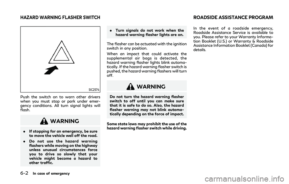
SIC2574
Push the switch on to warn other drivers
when you must stop or park under emer-
gency conditions. All turn signal lights will
flash.
WARNING
.If stopping for an emergency, be sure
to move the vehicle well off the road.
. Do not use the hazard warning
flashers while moving on the highway
unless unusual circumstances force
you to drive so slowly that your
vehicle might become a hazard to
other traffic. .
Turn signals do not work when the
hazard warning flasher lights are on.
The flasher can be actuated with the ignition
switch in any position.
When an impact that could activate the
supplemental air bags is detected, the
hazard warning flasher lights blink automa-
tically. If the hazard warning flasher switch is
pushed, the hazard warning flashers will turn
off.
WARNING
Do not turn the hazard warning flasher
switch to off until you can make sure
that it is safe to do so. Also, the hazard
flasher warning may not blink automa-
tically depending on the force of impact.
Some state laws may prohibit the use of the
hazard warning flasher switch while driving. In the event of a roadside emergency,
Roadside Assistance Service is available to
you. Please refer to your Warranty Informa-
tion Booklet (U.S.) or Warranty & Roadside
Assistance Information Booklet (Canada) for
details.
HAZARD WARNING FLASHER SWITCHROADSIDE ASSISTANCE PROGRAM
Page 333 of 468

To shut off the engine in an emergency
situation while driving, perform the follow-
ing procedure:
.Rapidly push the push-button ignition
switch 3 consecutive times in less than
1.5 seconds, or
. Push and hold the push-button ignition
switch for more than 2 seconds. If you have a flat tire, follow the instructions
in this section.
TIRE PRESSURE MONITORING
SYSTEM (TPMS)
This vehicle is equipped with the Tire
Pressure Monitoring System (TPMS). It
monitors tire pressure of all tires except the
spare. When the low tire pressure warning
light is lit and the “Tire Pressure Low - Add
Air” warning appears in the vehicle informa-
tion display, one or more of your tires is
significantly under-inflated. If the vehicle is
being driven with low tire pressure, the
TPMS will activate and warn you of it by
the low tire pressure warning light. This
system will activate only when the vehicle is
driven at speeds above 16 MPH (25 km/h).
For more details, see “Warning lights, in-
dicator lights and audible reminders” (P.2-
10) and “Tire Pressure Monitoring System
(TPMS)” (P.5-5).
WARNING
.
Radio waves could adversely affect
electric medical equipment. Those
who use a pacemaker should contact
the electric medical equipment man-
ufacturer for the possible influences
before use. .
If the low tire pressure warning light
illuminates while driving, avoid sud-
den steering maneuvers or abrupt
braking, reduce vehicle speed, pull
off the road to a safe location and
stop the vehicle as soon as possible.
Driving with under-inflated tires may
permanently damage the tires and
increase the likelihood of tire failure.
Serious vehicle damage could occur
and may lead to an accident and
could result in serious personal injury.
Check the tire pressure for all four
tires. Adjust the tire pressure to the
recommended COLD tire pressure
shown on the Tire and Loading
Information label to turn the low tire
pressure warning light OFF. If the
light still illuminates while driving
after adjusting the tire pressure, a
tire may be flat. If you have a flat tire,
replace it with a spare tire (if so
equipped).
. Since the spare tire is not equipped
with the TPMS, when a spare tire is
mounted or a wheel is replaced, the
TPMS will not function and the low
tire pressure warning light will flash
for approximately 1 minute. The light
will remain on after 1 minute. Have
your tires replaced and/or TPMS
system reset as soon as possible. It
In case of emergency6-3
EMERGENCY ENGINE SHUT OFF FLAT TIRE
Page 359 of 468

8 Do-it-yourself
Maintenance precautions ............................................... 8-3
Engine compartment check locations ......................... 8-4VR30DDTT engine ..................................................... 8-4
2.0L turbo gasoline engine ...................................... 8-5
Engine cooling system (for VR30DDTT
engine models) ................................................................... 8-6
Checking engine coolant level ................................ 8-7
Changing engine coolant .......................................... 8-7
Engine cooling system (for 2.0L turbo gasoline
engine models) ................................................................... 8-8
Checking engine coolant level ................................. 8-8
Changing engine coolant .......................................... 8-9
Intercooler cooling system (for VR30DDTT
engine models) ................................................................... 8-9 Checking intercooler coolant level ...................... 8-10
Changing intercooler coolant ............................... 8-10
Engine oil ........................................................................\
.. 8-10 Checking engine oil level ......................................... 8-11
Changing engine oil and filter ................................ 8-11
Automatic Transmission Fluid (ATF) ........................ 8-14
Power steering fluid (models with hydraulic pump
electric power steering) ................................................ 8-14
Brake fluid ........................................................................\
. 8-15
Window washer fluid .................................................... 8-15 Battery ........................................................................\
...... 8-16
Main battery location ............................................ 8-17
Auxiliary battery location (for 2.0L turbo
gasoline engine models) ........................................ 8-17
Checking battery fluid level .................................. 8-18
Jump starting ........................................................... 8-19
Variable voltage control system ................................ 8-19
Drive belts ........................................................................\
8-19
Spark plugs ..................................................................... 8-20 Replacing spark plugs ............................................ 8-21
Air cleaner ........................................................................\
8-21
Windshield wiper blades .............................................. 8-22 Cleaning ..................................................................... 8-22
Replacing ................................................................... 8-22
Brakes ........................................................................\
........ 8-23 Self-adjusting brakes ............................................. 8-23
Brake pad wear warning ....................................... 8-23
Fuses ........................................................................\
.......... 8-23 Engine compartment ............................................. 8-24
Passenger compartment ....................................... 8-25
Intelligent Key battery replacement ......................... 8-26
Lights ........................................................................\
......... 8-29 Headlights ................................................................. 8-29
Exterior and interior lights ................................... 8-30
Page 408 of 468

9-4Maintenance and schedules
Warning lights and chimes:Make sure that
all warning lights and chimes are operating
properly.
Windshield defroster: Check that the air
comes out of the defroster outlets properly
and in sufficient quantity when operating
the heater or air conditioner.
Windshield wiper and washer*: Check that
the wipers and washer operate properly and
that the wipers do not streak.
Under the hood and vehicle
The maintenance items listed here should be
checked periodically (for example, each time
you check the engine oil or refuel).
Battery*: Check the fluid level in each cell. It
should be between the MAX and MIN lines.
Vehicles operated in high temperatures or
under severe condition require frequent
checks of the battery fluid level.
NOTE:
Care should be taken to avoid situations
that can lead to potential battery discharge
and potential no-start conditions such as:
1. Installation or extended use of electro-
nic accessories that consume battery
power when the engine is not running
(Phone chargers, GPS, DVD players,
etc.) 2.
Vehicle is not driven regularly and/or
only driven short distances.
In these cases, the battery may need to be
charged to maintain battery health.
Brake fluid level*: Make sure that the brake
fluid level is between the MAX and MIN lines
on the reservoir.
Engine coolant level*: Check the coolant
level when the engine is cold.
Intercooler coolant level*: Check the coolant
level when the engine is cold.
Engine drive belts*: Make sure that no belt is
frayed, worn, cracked or oily.
Engine oil level*: Check the level after
parking the vehicle on a level spot and
turning off the engine. Wait more than 15
minutes for the oil to drain back into the oil
pan.
Exhaust system: Make sure there are no
loose supports, cracks or holes. If the sound
of the exhaust seems unusual or there is a
smell of exhaust fumes, immediately have
the exhaust system inspected. It is recom-
mended you visit an INFINITI retailer for this
service. (See “Precautions when starting and
driving” (P.5-4).)
Fluid leaks: Check under the vehicle for fuel,
oil, water or other fluid leaks after the
vehicle has been parked for a while. Water
dripping from the air conditioner after use is normal. If you should notice any leaks or if
gasoline fumes are evident, check for the
cause and have it corrected immediately.
Power steering fluid level* and lines:
Check
the level when the fluid is cold, with the
engine off. Check the lines for proper
attachment, leaks, cracks, etc.
Radiator and hoses: Check the front of the
radiator and clean off any dirt, insects,
leaves, etc., that may have accumulated.
Make sure the hoses have no cracks, defor-
mation, rot or loose connections.
Underbody: The underbody is frequently
exposed to corrosive substances such as
those used on icy roads or to control dust. It
is very important to remove these sub-
stances, otherwise rust will form on the
floor pan, frame, fuel lines and around the
exhaust system. At the end of winter, the
underbody should be thoroughly flushed
with plain water, being careful to clean
those areas where mud and dirt may accu-
mulate. For additional information, see
“Cleaning exterior” (P.7-2).
Windshield washer fluid*: Check that there
is adequate fluid in the reservoir.
Page 455 of 468

Floor mat installation ............................................ 7-6
FluidAutomatic Transmission Fluid (ATF) ....... 8-14
Brake fluid ....................................................... 8-15
Capacities and
recommended fluids/lubricants ................. 10-2
Engine coolant .................................................. 8-6
Engine oil ........................................................ 8-10
Power steering fluid ..................................... 8-14
Window washer fluid ................................... 8-15
Fog light switch ................................................... 2-42
Forward Emergency Braking (FEB) ............ 5-106
Forward Emergency Braking (FEB) system
warning light .......................................................... 2-11
Front passenger air bag and status light ..... 1-50
Front power seat adjustment ............................. 1-3
Front seat Front seat adjustment .................................... 1-3
Fuel
Capacities and
recommended fluids/lubricants ................. 10-2
Fuel economy .............................................. 5-124
Fuel information ............................... 10-4, 10-6
Fuel octane rating ............................ 10-4, 10-6
Fuel-filler cap .................................................. 3-26
Fuel-filler door ............................................... 3-26
Gauge .................................................................. 2-9
Fuel Efficient Driving Tips .............................. 5-123
Fuses ....................................................................... 8-23
Fusible links ........................................................... 8-25G
Garage door opener
HomeLink®Universal Transceiver ............ 2-58
Gas cap ................................................................... 3-26
Gauge ........................................................................\
. 2-6
Engine coolant temperature gauge ............ 2-8
Fuel gauge ......................................................... 2-9
Odometer ............................................................ 2-7
Speedometer ...................................................... 2-7
Tachometer ....................................................... 2-8
Trip computer ................................................. 2-27
General maintenance ............................................. 9-2
Glove box ............................................................... 2-48
H
Hazard warning flasher switch ........................... 6-2
Head restraints/headrests .................................. 1-8
Headlights Aiming control (See Adaptive Front
lighting System (AFS)) ................................ 2-40
Headlight switch ............................................ 2-36
Heated seats ......................................................... 2-43
Heated steering wheel ....................................... 2-45
Heater Engine block heater ................................... 5-143
High beam assist ................................................. 2-37
Hill start assist system ..................................... 5-137
HomeLink
®Universal Transceiver .................. 2-58
Hood release ......................................................... 3-23 Hook
Coat hooks ..................................................... 2-50
Trunk hooks ................................................... 2-50
Horn ........................................................................\
. 2-42
Hydraulic pump electric power steering ..... 5-128
I
Idling Stop System ............................................ 5-138
Idling Stop System indicator light .................. 2-16
Idling Stop System reminder buzzer .............. 2-18
Ignition switch
(Push-button) ................................................. 5-11
Automatic transmission models ................ 5-16
Immobilizer system .............................................. 2-31
Indicator
Lights ................................................................ 2-16
Vehicle information display ........................ 2-19
Indicator lights ...................................................... 2-16
Indicators for operation (vehicle
information display) ............................................ 2-21
INFINITI Drive Mode Selector ......................... 5-22
INFINITI InTouch Owner’s Manual .................. 4-2
INFINITI Vehicle Immobilizer System ............ 2-31 Engine start ..................................................... 2-31
Inside mirror .......................................................... 3-30
Inspection/maintenance (I/M) test ............. 10-25
Instrument brightness control ......................... 2-41
Instrument panel ..................................................... 2-5
Intelligent All-Wheel Drive (AWD) ............... 5-125
Intelligent Cruise Control (ICC) ....................... 5-74
11-3