Windshield INFINITI Q50 2021 User Guide
[x] Cancel search | Manufacturer: INFINITI, Model Year: 2021, Model line: Q50, Model: INFINITI Q50 2021Pages: 484, PDF Size: 1.86 MB
Page 254 of 484
5-30Starting and driving
The displayed keys on the lower display may
vary depending on models, specifications
and software versions.
ACTIVE LANE CONTROL LIM-
ITATIONS
WARNING
Listed below are the limitations for
Active Lane Control. Failure to operate
the vehicle in accordance with these
limitations could result in serious injury
or death.
.Active Lane Control is primarily in-
tended for use on well-developed
freeways or highways. It may not
detect the lane markers for certain
roads, weather or driving conditions.
. Using Active Lane Control under
some conditions of road, lane marker
or weather, or if you attempt to
change lanes without using the lane
change signal could lead to an un-
expected system operation. In such
conditions, you need to correct the
vehicle’s direction with your steering
operation to avoid accidents.
. Active Lane Control will not operate
at speeds below approximately 45 MPH (70 km/h) or if it cannot detect
lane markers.
. Active Lane Control may not operate
properly and should not be used
under the following conditions:
— During bad weather (rain, fog, snow, etc.).
— When driving on slippery roads, such as on ice or snow, etc.
— When driving on winding or un- even roads.
— When there is a lane closure due to road repairs.
— When driving in a makeshift lane.
— When driving on roads where the lane width is too narrow.
— When driving with a tire that is not within normal tire conditions
(for example, tire wear, low tire
pressure, installation of spare tire,
tire chains, non-standard wheels).
— When the vehicle is equipped with non-original steering parts or sus-
pension parts.
. Active Lane Control may or may not
operate properly under the following
conditions: — On roads where there are multi-
ple parallel lane markers; lane
markers that are faded or not
painted clearly; yellow painted
lane markers; non-standard lane
markers; or lane markers covered
with water, dirt, snow, etc.
— On roads where discontinued lane markers are still detectable.
— On roads where there are sharp curves.
— On roads where there are sharply contrasting objects, such as sha-
dows, snow, water, wheel ruts,
seams or lines remaining after
road repairs. (Active Lane Control
could detect these items as lane
markers.)
— On roads where the traveling lane merges or separates.
— When the vehicle’s traveling di- rection does not align with the
lane marker.
— When traveling close to the ve- hicle in front of you, which ob-
structs the lane camera unit
detection range.
— When rain, snow, dirt or object adheres to the windshield in front
Page 256 of 484

5-32Starting and driving
Action to take:
If the chassis control warning appears, pull
off the road to a safe location and stop the
vehicle. Turn the engine off and restart the
engine. If the chassis control warning con-
tinues to illuminate, have the system
checked. It is recommended you visit an
INFINITI retailer for this service.
SSD0453
SYSTEM MAINTENANCE
The lane camera unitfor Active Lane
Control is located above the inside mirror. To
keep the proper operation of Active Lane
Control and prevent a system malfunction,
be sure to observe the following:
. Always keep the windshield clean.
. Do not attach a sticker (including trans-
parent material) or install an accessory
near the camera unit.
. Do not place reflective materials, such as
white paper or a mirror, on the instru-
ment panel. The reflection of sunlight
may adversely affect the camera unit’s
capability of detecting the lane markers. .
Do not strike or damage the areas around
the camera unit. Do not touch the
camera lens or remove the screw located
on the camera unit. It is recommended
you contact an INFINITI retailer if the
camera unit is damaged due to an
accident.
Page 257 of 484

WARNING
Failure to follow the warnings and
instructions for proper use of the LDW
and LDP systems could result in serious
personal injury or death.
.The LDW and LDP systems will not
prevent loss of control. It is the
driver’s responsibility to stay alert,
drive safely, keep the vehicle in the
traveling lane, and be in control of
the vehicle at all times.
. The LDP system may activate if you
change lanes without first activating
your turn signal or, for example, if a
construction zone directs traffic to
cross an existing lane marker. If this
occurs, you may need to apply cor-
rective steering to complete your lane
change.
. Because the LDP system may not
activate under the road, weather,
and lane marker conditions described
in this section, it may not activate
every time your vehicle begins to
leave its lane and you will need to
apply corrective steering. .
Lane Departure Warning (LDW) system
— warns the driver with an indicator in the vehicle information display and
vibrations of the steering wheel that
the vehicle is beginning to leave the
driving lane.
. Lane Departure Prevention (LDP) system
(if so equipped)
— warns the driver with an indicator in the vehicle information display and
vibrations of the steering wheel, and
helps the driver to return the vehicle
to the center of the traveling lane.
JVS1124X
The LDW and LDP systems use a camerainstalled behind the windshield to monitor
the lane markers of your traveling lane.
Starting and driving5-33
LANE DEPARTURE WARNING
(LDW)/LANE DEPARTURE
PREVENTION (LDP) (if so equipped)
Page 262 of 484
5-38Starting and driving
dows, snow, water, wheel ruts,
seams or lines remaining after
road repairs. (The LDW and LDP
systems could detect these items
as lane markers.)
— On roads where the traveling lane merges or separates.
— When the vehicle’s traveling di- rection does not align with the
lane marker.
— When traveling close to the ve- hicle in front of you, which ob-
structs the lane camera unit
detection range.
— When rain, snow or dirt adheres to the windshield in front of the
lane camera unit.
— When the headlights are not bright due to dirt on the lens or
if the aiming is not adjusted
properly.
— When strong light enters the lane camera unit. (For example, the
light directly shines on the front
of the vehicle at sunrise or sun-
set.)
— When a sudden change in bright- ness occurs. (For example, when
the vehicle enters or exits a tunnel or under a bridge.)
JVS0826X
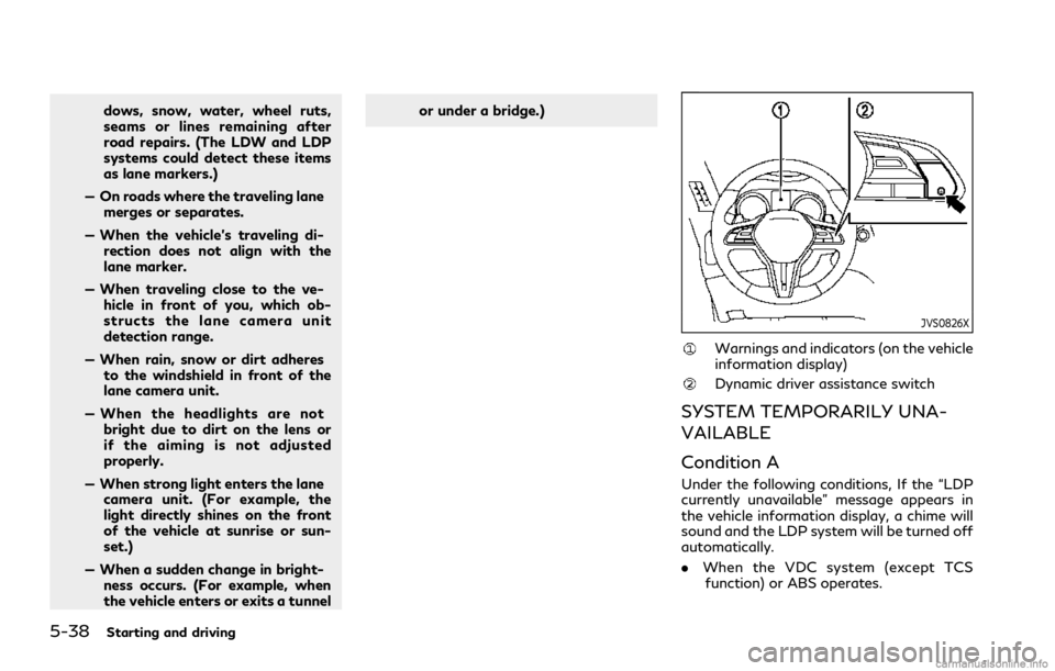
Warnings and indicators (on the vehicle
information display)
Dynamic driver assistance switch
SYSTEM TEMPORARILY UNA-
VAILABLE
Condition A
Under the following conditions, If the “LDP
currently unavailable” message appears in
the vehicle information display, a chime will
sound and the LDP system will be turned off
automatically.
.
When the VDC system (except TCS
function) or ABS operates.
Page 263 of 484

.When the VDC system is turned off.
. When the INFINITI Drive Mode Selector
is turned to the SNOW mode.
Action to take:
When the above conditions no longer exist,
push the dynamic driver assistance switch
again to turn the LDP system back on.
Condition B
LDW system: If the vehicle is parked in direct
sunlight under high temperature conditions
(over approximately 104°F (40°C)) and then
started, the LDW system may be deacti-
vated automatically. The “high cabin tem-
perature” warning message will appear in
the vehicle information display.
LDP system: If the vehicle is parked in direct
sunlight under high temperature conditions
(over approximately 104°F (40°C)) and then
the LDP system is turned on, the LDP
system may be deactivated automatically.
The “high cabin temperature” message will
appear in the vehicle information display.
The LDW and LDP systems are not available
until the conditions no longer exist.
Action to take:
When the above conditions no longer exist,
the LDW system will resume automatically.
For the LDP system, push the dynamic driver
assistance switch
again to turn the LDP system back on.
SYSTEM MALFUNCTION
LDW system:
If the LDW system malfunc-
tions, it will cancel automatically, and the
LDW “malfunction” message will appear in
the vehicle information display.
LDP system: If the LDP system malfunc-
tions, it will cancel automatically. The LDP
“malfunction” message will appear in the
vehicle information display.
Action to take:
Stop the vehicle in a safe location, place the
vehicle in the P (Park) position, turn the
engine off and restart the engine. If the
“malfunction” message continues to appear,
have the system checked. It is recommended
you visit an INFINITI retailer for this service.
SSD0453
SYSTEM MAINTENANCE
The lane camera unitfor LDW/LDP
systems is located above the inside mirror.
To keep the proper operation of LDW/LDP
systems and prevent a system malfunction,
be sure to observe the following:
. Always keep the windshield clean.
. Do not attach a sticker (including trans-
parent material) or install an accessory
near the camera unit.
. Do not place reflective materials, such as
white paper or a mirror, on the instru-
ment panel. The reflection of sunlight
may adversely affect the camera unit’s
capability of detecting the lane markers.
Starting and driving5-39
Page 272 of 484
5-48Starting and driving
WARNING
Failure to follow the warnings and
instructions for proper use of the BSI
system could result in serious injury or
death.
.The BSI system is not a replacement
for proper driving procedures and is
not designed to prevent contact with
vehicles or objects. When changing
lanes, always use the side and rear
mirrors and turn and look in the
direction your vehicle will move to
ensure it is safe to change lanes.
Never rely solely on the BSI system.
. There is a limitation to the detection
capability of the radar. Not every
moving object or vehicle will be
detected. Using the BSI system under
some road, ground, lane marker,
traffic or weather conditions could
lead to improper system operation.
Always rely on your own operation to
avoid accidents.
The BSI system helps alert the driver of other
vehicles in adjacent lanes when changing
lanes, and helps assist the driver to return
the vehicle to the center of the traveling
lane.
JVS1125X
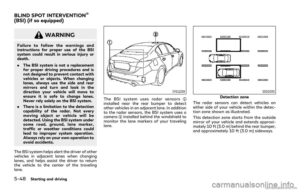
The BSI system uses radar sensorsinstalled near the rear bumper to detect
other vehicles in an adjacent lane. In addition
to the radar sensors, the BSI system uses a
camera
installed behind the windshield to
monitor the lane markers of your traveling
lane.
SSD1030
Detection zone
The radar sensors can detect vehicles on
either side of your vehicle within the detec-
tion zone shown as illustrated.
This detection zone starts from the outside
mirror of your vehicle and extends approxi-
mately 10 ft (3.0 m) behind the rear bumper,
and approximately 10 ft (3.0 m) sideways.
BLIND SPOT INTERVENTION®
(BSI) (if so equipped)
Page 276 of 484
5-52Starting and driving
.The radar sensors may not be able to
detect and activate BSI when certain
objects are present such as:
— Pedestrians, bicycles, animals.
— Vehicles such as motorcycles, low height vehicles, or high ground
clearance vehicles.
— Vehicles remaining in the detec- tion zone when you accelerate
from a stop.
— Oncoming vehicles.
— A vehicle merging into an adja- cent lane at a speed approxi-
mately the same as your vehicle.
— A vehicle approaching rapidly from behind.
— A vehicle which your vehicle over- takes rapidly.
— A vehicle that passes through the detection zone quickly.
. The radar sensor’s detection zone is
designed based on a standard lane
width. When driving in a wider lane,
the radar sensors may not detect
vehicles in an adjacent lane. When
driving in a narrow lane, the radar
sensors may detect vehicles driving
two lanes away. .
The radar sensors are designed to
ignore most stationary objects, how-
ever objects such as guardrails, walls,
foliage and parked vehicles may oc-
casionally be detected. This is a
normal operation condition.
. The camera may not detect lane
markers in the following situations
and the BSI system may not operate
properly.
— On roads where there are multi- ple parallel lane markers; lane
markers that are faded or not
painted clearly; yellow painted
lane markers; nonstandard lane
markers; lane markers covered
with water, dirt, snow, etc.
— On roads where discontinued lane markers are still detectable.
— On roads where there are sharp curves.
— On roads where there are sharply contrasting objects, such as sha-
dows, snow, water, wheel ruts,
seams or lines remaining after
road repairs.
— On roads where the traveling lane merges or separates. — When the vehicle’s traveling di-
rection does not align with the
lane markers.
— When traveling close to the ve- hicle in front of you, which ob-
structs the lane camera unit
detection range.
— When rain, snow or dirt adheres to the windshield in front of a lane
camera unit.
— When the headlights are not bright due to dirt on the lens or
if aiming is not adjusted properly.
— When strong light enters a lane camera unit. (For example: light
directly shines on the front of the
vehicle at sunrise or sunset.)
— When a sudden change in bright- ness occurs. (For example: when
the vehicle enters or exits a tunnel
or under a bridge.)
. Do not use the BSI system under the
following conditions because the sys-
tem may not function properly.
— During bad weather. (For exam- ple: rain, fog, snow, etc.)
— When driving on slippery roads, such as on ice or snow, etc.
Page 283 of 484

JVS1125X
SYSTEM MAINTENANCE
The two radar sensorsfor the BSI system
are located near the rear bumper. Always
keep the area near the radar sensors clean.
The radar sensors may be blocked by
temporary ambient conditions such as
splashing water, mist or fog.
The blocked condition may also be caused by
objects such as ice, frost or dirt obstructing
the radar sensors.
Check for and remove objects obstructing
the area around the radar sensors.
Do not attach stickers (including transparent
material), install accessories or apply addi-
tional paint near the radar sensors. Do not strike or damage the area around the
radar sensors.
It is recommended you visit an INFINITI
retailer if the area around the radar sensors
is damaged due to a collision.
The lane camera unit
for BSI system is
located above the inside mirror. To keep the
proper operation of BSI and prevent a
system malfunction, be sure to observe the
following:
. Always keep the windshield clean.
. Do not attach a sticker (including trans-
parent material) or install an accessory
near the camera unit.
. Do not place reflective materials, such as
white paper or a mirror, on the instru-
ment panel. The reflection of sunlight
may adversely affect the camera unit’s
capability of detecting the lane markers.
. Do not strike or damage the areas around
the camera unit. Do not touch the
camera lens or remove the screw located
on the camera unit. It is recommended
you contact an INFINITI retailer if the
camera unit is damaged due to an
accident.
Radio frequency statement
For USA
FCC ID: OAYSRR3B
This device complies with part 15 of the
FCC Rules. Operation is subject to the
following two conditions:
(1) this device may not cause harmful
interference, and
(2) this device must accept any interference
received, including interference that may
cause undesired operation.
CAUTION TO USERS
Changes or modifications not expressly
approved by the party responsible for
compliance could void the user’s authority
to operate the equipment.
For Canada
This device complies with Industry Canada
licence-exempt RSS standard(s). Operation
is subject to the following two conditions:
(1) this device may not cause interference,
and (2) this device must accept any inter-
ference, including interference that may
cause undesired operation of the device.
Frequency bands: 24.05 – 24.25 Ghz
The field strength of SRR3-B is below 250
millivolts/m measured at 3 metres with an
average detector.
Starting and driving5-59
Page 383 of 484

8 Do-it-yourself
Maintenance precautions ............................................... 8-2
Engine compartment check locations ......................... 8-3VR30DDTT engine ..................................................... 8-3
Engine cooling system ..................................................... 8-3 Checking engine coolant level ................................ 8-4
Changing engine coolant .......................................... 8-5
Intercooler cooling system ............................................. 8-5 Checking intercooler coolant level ......................... 8-6
Changing intercooler coolant .................................. 8-6
Engine oil ........................................................................\
..... 8-7
Checking engine oil level ........................................... 8-7
Changing engine oil and filter .................................. 8-7
Automatic Transmission Fluid (ATF) .......................... 8-9
Brake fluid ........................................................................\
8-10
Window washer fluid ................................................... 8-10
Battery ........................................................................\
....... 8-11
Checking battery fluid level .................................... 8-12
Jump starting ............................................................. 8-13
Variable voltage control system ................................. 8-13
Drive belts ........................................................................\
. 8-13
Spark plugs ....................................................................... 8-14 Replacing spark plugs .............................................. 8-14 Air cleaner ........................................................................\
8-15
Windshield wiper blades .............................................. 8-15
Cleaning ..................................................................... 8-15
Replacing ................................................................... 8-16
Brakes ........................................................................\
........ 8-16 Self-adjusting brakes ............................................. 8-16
Brake pad wear warning ....................................... 8-16
Fuses ........................................................................\
.......... 8-17 Engine compartment .............................................. 8-17
Passenger compartment ....................................... 8-18
Intelligent Key battery replacement ......................... 8-19
Lights ........................................................................\
......... 8-22 Headlights ................................................................. 8-23
Exterior and interior lights .................................... 8-23
Wheels and tires ............................................................. 8-25 Tire pressure ............................................................. 8-25
Tire labeling .............................................................. 8-29
Types of tires ........................................................... 8-31
Tire chains ................................................................. 8-33
Changing wheels and tires .................................. 8-34
Jacking up the vehicle and replacing tires ....... 8-37
Page 393 of 484
To check the window washer fluid level, use
your finger to plug the holeof the cap/
tube assembly, then remove it from the
reservoir. If there is no fluid in the tube,
add fluid.
Add a washer solvent to the washer for
better cleaning. In the winter season, add a
windshield washer antifreeze. Follow the
manufacturer’s instructions for the mixture
ratio.
Refill the reservoir more frequently when
driving conditions require an increased
amount of window washer fluid.
Recommended fluid is Genuine NISSAN
Windshield Washer Concentrate Cleaner &
Antifreeze or equivalent.
CAUTION
. Do not substitute engine anti-freeze
coolant for window washer solution.
This may result in damage to the
paint.
. Do not fill the window washer re-
servoir with washer fluid concen-
trates at full strength. Some methyl
alcohol based washer fluid concen-
trates may permanently stain the
grille if spilled while filling the win-
dow washer reservoir. .
Pre-mix washer fluid concentrates
with water to the manufacturer’s
recommended levels before pouring
the fluid into the window washer
reservoir. Do not use the window
washer reservoir to mix the washer
fluid concentrate and water. .
Keep the battery surface clean and dry.
Clean the battery with a solution of
baking soda and water.
. Make certain the terminal connections
are clean and securely tightened.
. If the vehicle is not to be used for 30 days
or longer, disconnect the negative (−)
battery terminal cable to prevent dis-
charging it.
NOTE:
Care should be taken to avoid situations
that can lead to potential battery discharge
and potential no-start conditions such as:
1. Installation or extended use of electro-
nic accessories that consume battery
power when the engine is not running
(Phone chargers, GPS, DVD players,
etc.)
2. Vehicle is not driven regularly and/or
only driven short distances.
In these cases, the battery may need to be
charged to maintain battery health.
WARNING
. Do not expose the battery to flames
or electrical sparks. Hydrogen gas
generated by the battery is explosive.
Do not allow battery fluid to contact
your skin, eyes, fabrics, or painted
Do-it-yourself8-11
BATTERY