display INFINITI Q50 2021 Owner's Guide
[x] Cancel search | Manufacturer: INFINITI, Model Year: 2021, Model line: Q50, Model: INFINITI Q50 2021Pages: 484, PDF Size: 1.86 MB
Page 161 of 484
LOG-IN FUNCTION
After setting up the user information, the
system will automatically recognize the user
upon turning on the vehicle.
There will be a personalized welcome greet-
ing and screen prompt to log-in.
This feature allows 4 drivers to use their
own registration, drive mode, driving posi-
tion, air conditioner, and auto settings and
memorizes these custom settings.
The log-in user can be changed on the
welcome greeting screen or the User Profiles
screen. For more details, see the INFINITI
InTouch
TMOwner’s Manual.
The log-in function is linked to the following
items:
. Meter
. Audio
. Navigation system display (if so
equipped)
. Navigation settings (if so equipped)
. Air conditioner
. Memory seat (if so equipped)
. Engine/Transmission
. Steering
. Suspension (if so equipped)
. Active trace control system .
Driver assistance* (if so equipped)
. Vehicle settings
*: except for the Forward Emergency Brak-
ing (FEB) system
WARNING
The Intelligent Key transmits radio
waves when the buttons are pushed.
The FAA advises that the radio waves
may affect aircraft navigation and com-
munication systems. Do not operate the
Intelligent Key while on an airplane.
Make sure the buttons are not operated
unintentionally when the unit is stored
during a flight.
It is possible to lock/unlock all doors and
fuel-filler door, open the trunk lid, activate
the panic alarm and open the windows by
pushing the buttons on the Intelligent Key
from outside the vehicle.
Before locking the doors, make sure the
Intelligent Key is not left in the vehicle.
The remote keyless entry function can
operate at a distance of approximately 33
ft (10 m) from the vehicle. (The effective
distance depends upon the conditions
around the vehicle.)
As many as 4 Intelligent Keys can be used
with one vehicle. For information concerning
the purchase and use of additional Intelli-
gent Keys, contact an INFINITI retailer.
The buttons on the Intelligent Key will not
Pre-driving checks and adjustments3-15
REMOTE KEYLESS ENTRY SYSTEM
Page 167 of 484

CANCELING A REMOTE ENGINE
START
To cancel a remote engine start, perform one
of the following:
.Aim the Intelligent Key at the vehicle and
push and hold the remote engine start
button until the parking lights turn
off.
. Turn on the hazard warning flashers.
. Cycle the ignition switch ON and then
OFF.
. The extended engine run time has ex-
pired.
. The first 10 minute timer has expired.
. The engine hood has been opened.
. The shift lever is moved out of P (Park).
. The alarm sounds due to illegal entry into
the vehicle.
. The ignition switch is pushed without an
Intelligent Key in the vehicle.
. The ignition switch is pushed with an
Intelligent Key in the vehicle but the
brake pedal is not depressed.
CONDITIONS THE REMOTE EN-
GINE START WILL NOT WORK
The remote engine start will not operate if
any of the following conditions are present:
. The ignition switch is placed in the ON
position.
. The hood is not securely closed.
. The hazard warning lights are on.
. The engine is still running. The engine
must be completely stopped. Wait at
least 6 seconds if the engine goes from
running to off. This is not applicable
when extending engine run time.
. The remote engine start
button is
not pushed and held for at least 2
seconds.
. The remote engine start
button is
not pushed and held within 5 seconds of
pushing the LOCK button.
. The brake pedal is depressed.
. The doors are not closed and locked.
. The trunk is open.
. The Intelligent Key warning message is
displayed in the vehicle information dis-
play.
. The alarm sounds due to illegal entry into
the vehicle.
. Two remote engine starts, or a single
remote engine start with an extension,
have already been used. .
The vehicle is not in P (Park).
. The remote engine start function has
been switched to OFF in the settings
menu on the lower display. For additional
information, see the INFINITI InTouch
TM
Owner’s Manual.
The remote engine start may display a
warning or indicator in the vehicle informa-
tion display. For an explanation of the
warning or indicator, see “Indicators for
operation” (P.2-21).
Pre-driving checks and adjustments3-21
Page 172 of 484
3-26Pre-driving checks and adjustments
Indicator Light (MIL) to come on.
. Never pour fuel into the throttle body
to attempt to start your vehicle.
. Do not fill a portable fuel container in
the vehicle or trailer. Static electricity
can cause an explosion of flammable
liquid, vapor or gas in any vehicle or
trailer. To reduce the risk of serious
injury or death when filling portable
fuel containers:
— Always place the container on the ground when filling.
— Do not use electronic devices when filling.
— Keep the pump nozzle in contact with the container while you are
filling it.
— Use only approved portable fuel containers for flammable liquid.
CAUTION
. If fuel is spilled on the vehicle body,
flush it away with water to avoid
paint damage.
. Insert the cap straight into the fuel-
filler tube, then tighten the fuel-filler
cap until a single click is heard. Failure to tighten the fuel-filler cap properly
may cause the
Malfunction In-
dicator Light (MIL) to illuminate. If
the
light illuminates because the
fuel-filler cap is loose or missing,
tighten or install the cap and con-
tinue to drive the vehicle. The
light should turn off after a few
driving trips. If thelight does
not turn off after a few driving trips,
have the vehicle inspected. It is
recommended you visit an INFINITI
retailer for this service.
. The Loose Fuel Cap warning will
appear if the fuel-filler cap is not
properly tightened. It may take a few
driving trips for the warning to be
displayed. Failure to tighten the fuel-
filler cap properly after the Loose
Fuel Cap warning appears may cause
the
Malfunction Indicator Light
(MIL) to illuminate.
. For additional information, see “Mal-
function Indicator Light (MIL)” (P.2-
15).
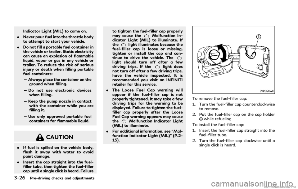
JVP0204X
To remove the fuel-filler cap:
1. Turn the fuel-filler cap counterclockwise
to remove.
2. Put the fuel-filler cap on the cap holder
while refueling.
To install the fuel-filler cap:
1. Insert the fuel-filler cap straight into the fuel-filler tube.
2. Turn the fuel-filler cap clockwise until a single click is heard.
Page 173 of 484
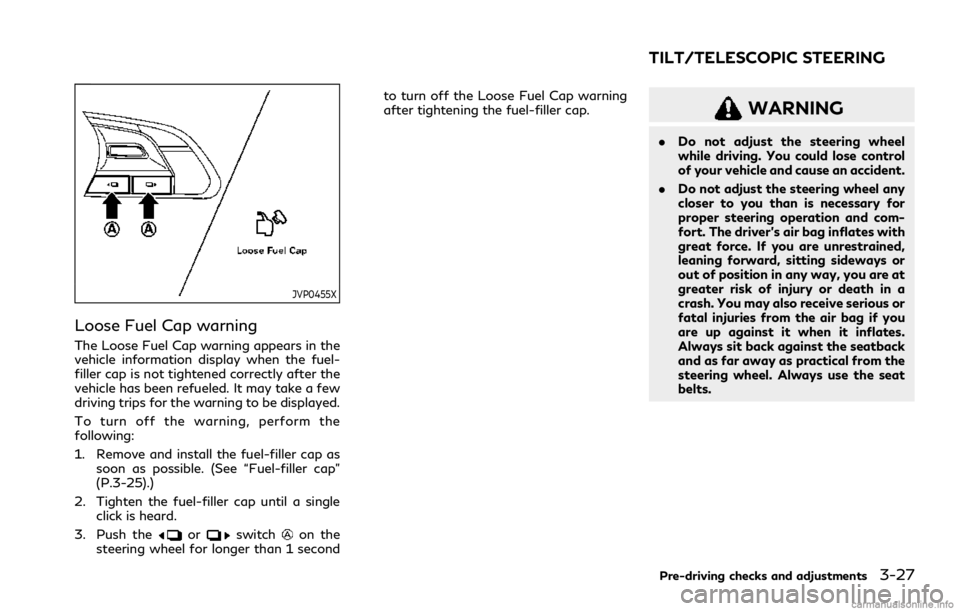
JVP0455X
Loose Fuel Cap warning
The Loose Fuel Cap warning appears in the
vehicle information display when the fuel-
filler cap is not tightened correctly after the
vehicle has been refueled. It may take a few
driving trips for the warning to be displayed.
To turn off the warning, perform the
following:
1. Remove and install the fuel-filler cap assoon as possible. (See “Fuel-filler cap”
(P.3-25).)
2. Tighten the fuel-filler cap until a single click is heard.
3. Push the
orswitchon the
steering wheel for longer than 1 second to turn off the Loose Fuel Cap warning
after tightening the fuel-filler cap.
WARNING
.
Do not adjust the steering wheel
while driving. You could lose control
of your vehicle and cause an accident.
. Do not adjust the steering wheel any
closer to you than is necessary for
proper steering operation and com-
fort. The driver’s air bag inflates with
great force. If you are unrestrained,
leaning forward, sitting sideways or
out of position in any way, you are at
greater risk of injury or death in a
crash. You may also receive serious or
fatal injuries from the air bag if you
are up against it when it inflates.
Always sit back against the seatback
and as far away as practical from the
steering wheel. Always use the seat
belts.
Pre-driving checks and adjustments3-27
TILT/TELESCOPIC STEERING
Page 179 of 484

The memory seat system has two features:
.Entry/exit function
. Memory storage
ENTRY/EXIT FUNCTION
This system is designed so that the driver’s
seat and steering column will automatically
move when the shift lever is in the P (Park)
position. This allows the driver to get into
and out of the driver’s seat more easily.
The driver’s seat will slide backward and the
steering wheel will move up when the
driver’s door is opened with the ignition
switch in the LOCK position.
The driver’s seat and steering wheel will
return to the previous positions when the
ignition switch is pushed to the ACC posi-
tion.
The driver’s seat will not return to the
previous positions if the seat or steering
adjusting switch is operated when the seat is
at the exit position.
Cancel or activate entry/exit func-
tion
All the following conditions must be met
before cancelling or activating the entry/exit
function.
.The ignition switch is placed in the LOCK
position. .
The entry/exit function is not in opera-
tion.
. The following switches are not operated.
— Seat memory switches
— Power seat switches
— Electric tilting/telescopic steering wheel switch
The entry/exit function can be activated or
canceled by pushing and holding the SET
switch for more than 10 seconds.
The entry/exit function can also be acti-
vated or canceled if the [Lift Steering Wheel
on Exit] or [Slide Driver Seat Back on Exit]
key is turned to ON or OFF in the [Settings]
menu on the lower display. (See the INFINITI
InTouch
TMOwner’s Manual. The displayed
keys on the lower display may vary depend-
ing on models, specifications and software
versions.)
Initialize entry/exit function
If the battery cable is disconnected, or if the
fuse opens, the entry/exit function will not
work though this function was set on before.
In such a case, after connecting the battery
or replacing with a new fuse, open and close
the driver’s door more than two times after
the ignition switch is switched from the ON
position to the LOCK position. The entry/
exit function will be activated.
JVP0240X
MEMORY STORAGE
Two positions for the driver’s seat, steering
column and outside mirrors can be stored in
the memory switch. Follow these procedures
to use the memory system.
1. Adjust the driver’s seat, steering column and outside mirrors to the desired posi-
tions by manually operating each adjust-
ing switch. For additional information,
see “Seats” (P.1-2), “Tilt/telescopic
steering” (P.3-27) and “Outside mirrors”
(P.3-30).
2. Push the SET switch and, within 5 seconds, push the memory switch (1 or
2) fully for at least 1 second.
Pre-driving checks and adjustments3-33
MEMORY SEAT (if so equipped)
Page 180 of 484

3-34Pre-driving checks and adjustments
The indicator light for the pushed mem-
ory switch will stay on for approximately
5 seconds after pushing the switch.
When the memory is stored in the
memory switch (1 or 2), a buzzer will
sound.
If memory is stored in the same memory
switch, the previous memory will be
deleted.
Confirming memory storage
Push the SET switch. If the main memory
has not been stored, the indicator light will
come on for approximately 0.5 seconds.
When the memory has stored in position,
the indicator light will stay on for approxi-
mately 5 seconds.
Selecting the memorized position
1. Move the shift lever to the P (Park)position.
2. Push the memory switch (1 or 2) fully for at least 1 second.
The driver’s seat, steering column and
outside mirrors will move to the memor-
ized position with the indicator light
flashing, and then the light will stay on
for approximately 5 seconds.
Linking log-in function to a stored
memory position
The log-in function can be linked to a stored
memory position with the following proce-
dure.
1. Place the ignition switch in the ONposition while carrying an Intelligent
Key that was registered to the vehicle
with the log-in function. For more de-
tails, see “Log-in function” (P.3-15).
2. Adjust the position of the driver’s seat, steering column and outside mirrors
manually. See “Seats” (P.1-2), “Tilt/tele-
scopic steering” (P.3-27) and “Outside
mirrors” (P.3-30).
3. Place the ignition switch in the OFF position.
The next time you log in (selecting the user
on the display) after placing the ignition
switch in the ON position while carrying the
Intelligent Key, the system will automatically
adjust to the memorized driving position.
SYSTEM OPERATION
The memory seat system will not work or
will stop operating under the following
conditions:
. When the vehicle speed is above 0 MPH
(0 km/h) or 4 MPH (7 km/h) for some
limited functions such linking an Intelli- gent Key to the vehicle when the power
source is turned on from off or during the
Exit function.
. When any of the memory switches are
pushed while the memory seat is operat-
ing.
. When the adjusting switch for the dri-
ver’s seat and steering column is turned
on while the memory seat is operating.
. When the seat has already been moved
to the memorized position.
. When no seat position is stored in the
memory switch.
. When the shift lever is moved from the P
(Park) position to any other position.
Page 181 of 484

4 Monitor, climate, audio, phone and voice re-cognition systems
INFINITI InTouchTMOwner’s Manual ........................ 4-2
Safety precautions ........................................................... 4-2
RearView Monitor (if so equipped) ............................. 4-3
RearView Monitor system operation .................... 4-4
How to read the displayed lines ............................. 4-4
Difference between predictive and
actual distances ........................................................... 4-5
How to park with predictive course lines ............ 4-6
RearView Monitor settings ...................................... 4-7
RearView Monitor system limitations ................... 4-9
System maintenance ............................................... 4-10
Around View
®Monitor (if so equipped) .................. 4-11
Around View®Monitor system operation ......... 4-13
Around View®Monitor settings .......................... 4-20
Around View®Monitor system limitations ........ 4-22
System maintenance ............................................... 4-24
Camera aiding sonar function (for models with
Around View
®Monitor) ................................................ 4-25
Sonar system operation .......................................... 4-26
Turning on and off the sonar function ............... 4-26
Sonar system limitations ......................................... 4-29 System maintenance .............................................. 4-29
Moving Object Detection (MOD) (if
so equipped) ................................................................... 4-30
MOD system operation ......................................... 4-31
Turning the MOD system ON and OFF ........... 4-32
MOD system limitations ....................................... 4-33
System maintenance ............................................. 4-34
Ventilators ........................................................................\
4-35 Center ventilators ................................................... 4-35
Side ventilators ........................................................ 4-35
Rear ventilators ....................................................... 4-35
Heater and air conditioner .......................................... 4-36 Automatic air conditioner ..................................... 4-37
Climate settings ....................................................... 4-41
Operating tips .......................................................... 4-41
Servicing air conditioner ....................................... 4-42
Antenna ........................................................................\
... 4-43 Window antenna .................................................... 4-43
Satellite antenna .................................................... 4-43
Car phone or CB radio ................................................ 4-43
Page 182 of 484
4-2Monitor, climate, audio, phone and voice recognition systems
Refer to the INFINITI InTouchTMOwner’s
Manual that includes the following informa-
tion.
. Navigation system (if so equipped)
. Audio system
. Bluetooth
®Hands-Free Phone system
. INFINITI InTouchTMServices (if so
equipped)
. SiriusXM Traffic
TM(if so equipped)
. SiriusXM®Travel Link (if so equipped)
. SiriusXM®Radio
. Viewing information
. Other settings
. Voice recognition (if so equipped)
. Meter settings
. General system information
. Android Auto
TM
.Apple CarPlay®
WARNING
.Do not adjust the display controls,
heater and air conditioner controls or
audio controls while driving so that
full attention may be given to vehicle
operation.
. If you noticed any foreign objects
entering the system hardware, spilled
liquid on the system, or noticed
smoke or fumes coming out from the
system, or any other unusual opera-
tion is observed, stop using the
system immediately and contact the
nearest INFINITI retailer. Ignoring
such conditions may lead to an acci-
dent, fire or electric shock.
. Do not disassemble or modify this
system. If you do, it may lead to an
accident, fire, or electric shock.
. Park the vehicle in a safe location and
apply the parking brake to view
images on the touch screen display.
CAUTION
.Do not use the system when the
engine is not running for extended periods of time to prevent battery
discharge.
. The glass screen on the liquid crystal
display may break if it is hit with a
hard or sharp object. If the glass
screen breaks, do not touch it. Doing
so could result in an injury.
. Extreme temperature conditions [be-
low −4°F (−20°C) and above 158°F
(70°C)] could affect the performance
of the system.
INFINITI INTOUCHTMOWNER’S MANUALSAFETY PRECAUTIONS
Page 183 of 484
WAE0191X
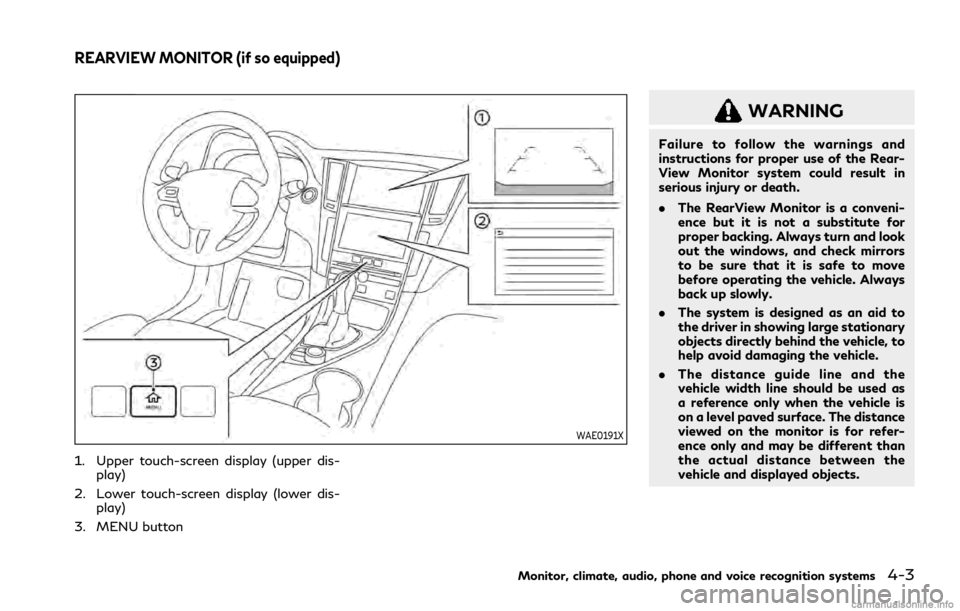
1. Upper touch-screen display (upper dis-play)
2. Lower touch-screen display (lower dis- play)
3. MENU button
WARNING
Failure to follow the warnings and
instructions for proper use of the Rear-
View Monitor system could result in
serious injury or death.
. The RearView Monitor is a conveni-
ence but it is not a substitute for
proper backing. Always turn and look
out the windows, and check mirrors
to be sure that it is safe to move
before operating the vehicle. Always
back up slowly.
. The system is designed as an aid to
the driver in showing large stationary
objects directly behind the vehicle, to
help avoid damaging the vehicle.
. The distance guide line and the
vehicle width line should be used as
a reference only when the vehicle is
on a level paved surface. The distance
viewed on the monitor is for refer-
ence only and may be different than
the actual distance between the
vehicle and displayed objects.
Monitor, climate, audio, phone and voice recognition systems4-3
REARVIEW MONITOR (if so equipped)
Page 184 of 484
4-4Monitor, climate, audio, phone and voice recognition systems
CAUTION
Do not scratch the camera lens when
cleaning dirt or snow from the front of
the camera.
The RearView Monitor system automatically
shows a rear view of the vehicle in the upper
display when the shift lever is shifted into
the R (Reverse) position. When activating
the RearView Monitor, the guide lines, the
icons and the messages may not be dis-
played immediately.
The radio can still be heard while the Rear-
View Monitor is active.
WAE0234X
To display the rear view, the RearView
Monitor system uses a cameralocated
just above the vehicle’s license plate.
REARVIEW MONITOR SYSTEM
OPERATION
With the ignition switch in the ON position,
move the shift lever to the R (Reverse)
position to operate the RearView Monitor.
WAE0241X
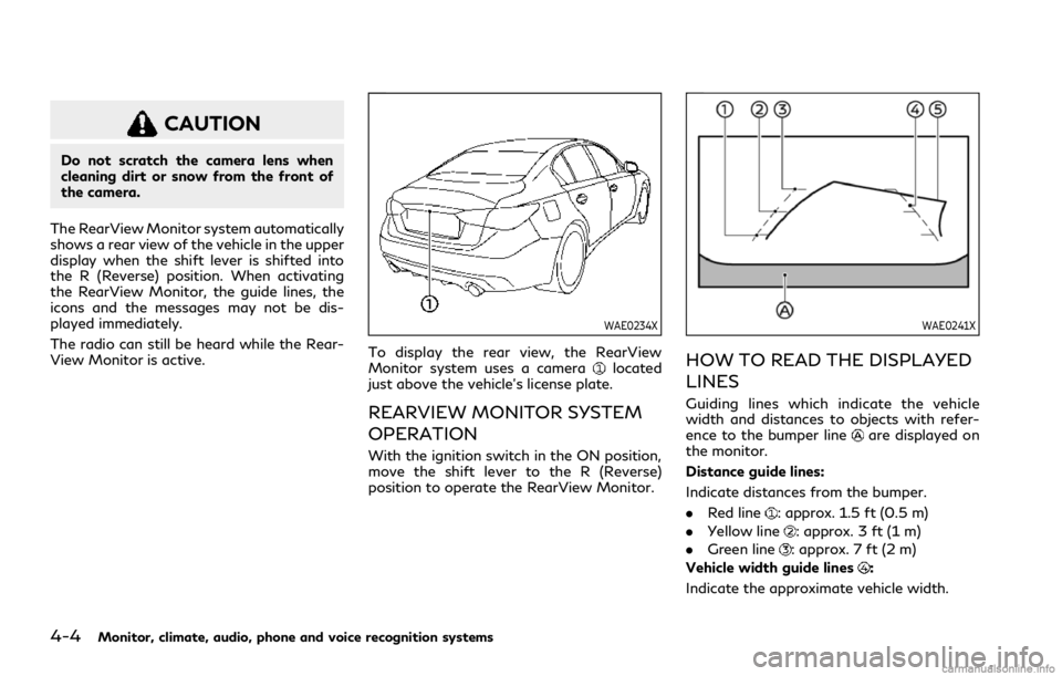
HOW TO READ THE DISPLAYED
LINES
Guiding lines which indicate the vehicle
width and distances to objects with refer-
ence to the bumper line
are displayed on
the monitor.
Distance guide lines:
Indicate distances from the bumper.
. Red line
: approx. 1.5 ft (0.5 m)
. Yellow line
: approx. 3 ft (1 m)
. Green line
: approx. 7 ft (2 m)
Vehicle width guide lines
:
Indicate the approximate vehicle width.