power steering INFINITI Q60 COUPE 2014 Owner's Manual
[x] Cancel search | Manufacturer: INFINITI, Model Year: 2014, Model line: Q60 COUPE, Model: INFINITI Q60 COUPE 2014Pages: 458, PDF Size: 4.27 MB
Page 18 of 458
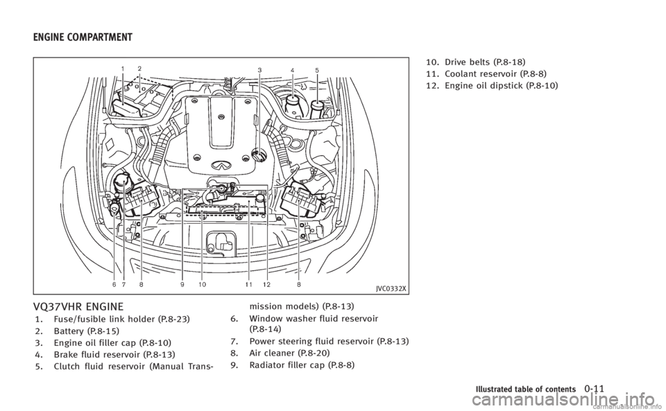
JVC0332X
VQ37VHR ENGINE
1. Fuse/fusible link holder (P.8-23)
2. Battery (P.8-15)
3. Engine oil filler cap (P.8-10)
4. Brake fluid reservoir (P.8-13)
5. Clutch fluid reservoir (Manual Trans-mission models) (P.8-13)
6. Window washer fluid reservoir (P.8-14)
7. Power steering fluid reservoir (P.8-13)
8. Air cleaner (P.8-20)
9. Radiator filler cap (P.8-8) 10. Drive belts (P.8-18)
11. Coolant reservoir (P.8-8)
12. Engine oil dipstick (P.8-10)
Illustrated table of contents0-11
ENGINE COMPARTMENT
Page 132 of 458
3 Pre-driving checks and adjustments
Keys.................................................................... 3-2
Intelligent Key ................................................. 3-2
Valet hand-off.................................................. 3-3
Doors .................................................................. 3-4 Locking with mechanical key ........................... 3-4
Opening and closing windows with the
mechanical key................................................ 3-4
Locking with inside lock knob ......................... 3-5
Locking with power door lock switch ............... 3-5
Automatic door locks....................................... 3-5
Intelligent Key system ......................................... 3-6 Intelligent Key operating range ....................... 3-8
Door locks/unlocks precaution ....................... 3-8
Intelligent Key operation ................................. 3-9
Battery saver system ..................................... 3-11
Warning signals............................................. 3-12
Troubleshooting guide ................................... 3-13
Remote keyless entry system............................. 3-14 How to use remote keyless entry system....... 3-14
Hood ................................................................. 3-17 Trunk lid ........................................................... 3-18
Trunk lid release switch ............................... 3-18
Trunk open request switch ........................... 3-18
Trunk release power cancel switch ............... 3-19
Interior trunk lid release .............................. 3-19
Unique front and rear parts (INFINITI Performance
Line model) ....................................................... 3-20
Fuel-filler door................................................... 3-21 Opening the fuel-filler door.......................... 3-21
Fuel-filler cap............................................... 3-21
Tilt/telescopic steering ...................................... 3-23 Manual operation (if so equipped) ............... 3-24
Electric operation (if so equipped) ............... 3-24
Sun visors......................................................... 3-24
Mirrors ............................................................. 3-25 Inside mirror................................................ 3-25
Outside mirrors............................................ 3-26
Vanity mirror................................................ 3-27
Automatic drive positioner (if so equipped) ....... 3-28 Seat synchronization function ..................... 3-28
Memory storage........................................... 3-29
System operation......................................... 3-30
Page 159 of 458
3-28Pre-driving checks and adjustments
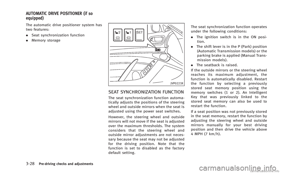
The automatic drive positioner system has
two features:
.Seat synchronization function
. Memory storage
JVP0223X
SEAT SYNCHRONIZATION FUNCTION
The seat synchronization function automa-
tically adjusts the positions of the steering
wheel and outside mirrors when the seat is
adjusted using the power seat switches.
However, the steering wheel and outside
mirrors will not move if the seat is adjusted
over the maximum thresholds. The system
considers that the steering wheel and
outside mirror adjustments are not neces-
sary because the seat may not be adjusted
for the driving position. Note that the
function is set to disabled as the factory
default setting. The seat synchronization function operates
under the following conditions:
.
The ignition switch is in the ON posi-
tion.
. The shift lever is in the P (Park) position
(Automatic Transmission models) or the
parking brake is applied (Manual Trans-
mission models).
. The seatback is raised.
If the outside mirrors or the steering wheel
reaches its maximum adjustment, the
function is automatically disabled. Restart
the function by selecting a previously
stored seat memory position using the
memory switches (1 or 2). An Intelligent
Key that was previously linked to the
stored seat memory can also be used to
restart the function.
If a seat position was not previously stored
in the seat memory, restart the function by
adjusting the steering wheel and outside
mirrors manually for your best driving
position and then drive the vehicle above
4 MPH (7 km/h).
AUTOMATIC DRIVE POSITIONER (if so
equipped)
Page 294 of 458

5 Starting and driving
Precautions when starting and driving................. 5-3
Exhaust gas (carbon monoxide) ....................... 5-3
Three-way catalyst........................................... 5-4
Tire Pressure Monitoring System (TPMS).......... 5-4
Avoiding collision and rollover......................... 5-6
Off-road recovery............................................. 5-7
Rapid air pressure loss ................................... 5-7
Drinking alcohol/drugs and driving ................. 5-8
All-Wheel Drive (AWD) driving safety precautions
(AWD models).................................................. 5-8
Push-button ignition switch ................................. 5-9 Intelligent Key system ..................................... 5-9
Operating range for engine start function ...... 5-10
Push-button ignition switch operation ........... 5-10
Push-button ignition switch positions ............ 5-11
Emergency engine shut off ............................ 5-11
Intelligent Key battery discharge ................... 5-12
Before starting the engine ................................. 5-12
Starting the engine ............................................ 5-13
Driving the vehicle ............................................. 5-14
Automatic transmission ................................. 5-14
Manual Transmission..................................... 5-19
Parking brake .................................................... 5-21
Automatic transmission models ..................... 5-21
Manual Transmission models ........................ 5-22 Cruise control.................................................... 5-22
Precautions on cruise control....................... 5-22
Cruise control operations ............................. 5-23
Intelligent Cruise Control (ICC) system (if
so equipped)..................................................... 5-24 Selecting the vehicle-to-vehicle distance
control mode ............................................... 5-25
Vehicle-to-vehicle distance control mode...... 5-25
Precautions on vehicle-to-vehicle distance
control mode ............................................... 5-26
Vehicle-to-vehicle distance control
mode operation ........................................... 5-28
Conventional (fixed speed) cruise
control mode ............................................... 5-41
Preview function (for Intelligent Cruise Control
system equipped models) ............................ 5-45
Break-in schedule ............................................. 5-46
Fuel Efficient Driving Tips .................................. 5-46
Increasing fuel economy.................................... 5-47
All-Wheel Drive (AWD) (if so equipped) .............. 5-48
Parking/parking on hills.................................... 5-49
Sonar system (if so equipped) .......................... 5-51 Sonar indicator ............................................ 5-52
Sonar system OFF switch ............................. 5-53
Power steering .................................................. 5-53
Page 346 of 458

SSD0929
SONAR SYSTEM OFF SWITCH
The sonar system OFF switch on the
instrument panel allows the driver to turn
the sonar system on and off. To turn the
sonar system on and off, the ignition
switch must be in the“ON”position. The
indicator light
*1on the switch will
illuminate when the system is turned off.
If the indicator light flashes when the
sonar system is not turned off, it may
indicate a malfunction in the sonar system.
WARNING
If the engine is not running or is turned off
while driving, the power assist for the
steering will not work. Steering will be
harder to operate.
The power assisted steering uses a hy-
draulic pump, driven by the engine, to
assist steering.
If the engine stops or the drive belt breaks,
you will still have control of the vehicle.
However, much greater steering effort is
needed, especially in sharp turns and at
low speeds.
BRAKING PRECAUTIONS
The brake system has two separate hy-
draulic circuits. If one circuit malfunctions,
you will still have braking at two wheels.
Vacuum assisted brakes
The brake booster aids braking by using
engine vacuum. If the engine stops, you
can stop the vehicle by depressing the
brake pedal. However, greater foot pres-
sure on the brake pedal will be required to
stop the vehicle and the stopping distance
will be longer.
When the brake pedal is depressed slowly
and firmly, you may hear a clicking noise
and feel a slight pulsation. This is normal
and indicates that the Brake Assist System
is operating.
Wet brakes
When the vehicle is washed or driven
through water, the brakes may get wet.
As a result, your braking distance will be
longer and the vehicle may pull to one side
during braking.
To dry brakes, drive the vehicle at a safe
speed while lightly tapping the brake pedal
to heat-up the brakes. Do this until the
brakes return to normal. Avoid driving the
Starting and driving5-53
POWER STEERING BRAKE SYSTEM
Page 351 of 458

5-58Starting and driving
Normal operation
The ABS operates at speeds above 3 to 6
MPH (5 to 10 km/h).
When the ABS senses that one or more
wheels are close to locking up, the actuator
rapidly applies and releases hydraulic
pressure. This action is similar to pumping
the brakes very quickly. You may feel a
pulsation in the brake pedal and hear a
noise from under the hood or feel a
vibration from the actuator when it is
operating. This is normal and indicates
that the ABS is operating properly. How-
ever, the pulsation may indicate that road
conditions are hazardous and extra care is
required while driving.The Vehicle Dynamic Control (VDC) system
uses various sensors to monitor driver
inputs and vehicle motion. Under certain
driving conditions, the VDC system helps
to perform the following functions.
.
Controls brake pressure to reduce
wheel slip on one slipping drive wheel
so power is transferred to a non
slipping drive wheel on the same axle.
. Controls brake pressure and engine
output to reduce drive wheel slip based
on vehicle speed (traction control func-
tion).
. Controls brake pressure at individual
wheels and engine output to help the
driver maintain control of the vehicle in
the following conditions:
— understeer (vehicle tends to not
follow the steered path despite
increased steering input)
— oversteer (vehicle tends to spin due
to certain road or driving condi-
tions).
The VDC system can help the driver to
maintain control of the vehicle, but it
cannot prevent loss of vehicle control in
all driving situations.
When the VDC system operates, the VDC
warning light
in the instrument panel flashes so note the following:
.
The road may be slippery or the system
may determine some action is required
to help keep the vehicle on the steered
path.
. You may feel a pulsation in the brake
pedal and hear a noise or vibration
from under the hood. This is normal
and indicates that the VDC system is
working properly.
. Adjust your speed and driving to the
road conditions.
See “Vehicle Dynamic Control (VDC) warn-
ing light” (P.2-17).
If a malfunction occurs in the system, the
VDC warning light
illuminates in the
instrument panel. The VDC system auto-
matically turns off.
The VDC OFF switch is used to turn off the
VDC system. The VDC off indicator
illuminates to indicate the VDC system is
off. When the VDC switch is used to turn off
the system, the VDC system still operates
to prevent one drive wheel from slipping by
transferring power to a non slipping drive
wheel. The VDC warning light
flashes if
this occurs. All other VDC functions are off,
and the VDC warning light
will not
flash. The VDC system is automatically
VEHICLE DYNAMIC CONTROL (VDC) SYSTEM
Page 367 of 458
6-12In case of emergency
When towing your vehicle, all State (Pro-
vincial in Canada) and local regulations for
towing must be followed. Incorrect towing
equipment could damage your vehicle.
Towing instructions are available from an
INFINITI retailer. Local service operators are
familiar with the applicable laws and
procedures for towing. To assure proper
towing and to prevent accidental damage
to your vehicle, INFINITI recommends that
you have a service operator tow your
vehicle. It is advisable to have the service
operator carefully read the following pre-
cautions.
WARNING
.Never ride in a vehicle that is being
towed.
. Never get under your vehicle after it has
been lifted by a tow truck.
CAUTION
.When towing, make sure that the trans-
mission, axles, steering system and
powertrain are in working condition. If
any unit is damaged, dollies must be used.
. Always attach safety chains before tow-
ing.
For information about towing your vehicle
behind a recreational vehicle (RV), see
“Flat towing” (P.9-19) of this manual.
TOWING YOUR VEHICLE
Page 382 of 458
8 Maintenance and do-it-yourself
Maintenance requirement.................................... 8-2
Scheduled maintenance .................................. 8-2
General maintenance....................................... 8-2
Where to go for service ................................... 8-2
General maintenance ........................................... 8-2 Explanation of maintenance items ................... 8-2
Maintenance precautions ..................................... 8-5
Engine compartment check locations ................... 8-7 VQ37VHR engine ............................................. 8-7
Engine cooling system ......................................... 8-8
Checking engine coolant level ......................... 8-9
Changing engine coolant ................................. 8-9
Engine oil .......................................................... 8-10
Checking engine oil level............................... 8-10
Changing engine oil and filter ....................... 8-10
Automatic transmission fluid (if so equipped) .... 8-12
Power steering fluid........................................... 8-13
Brake and clutch fluid ....................................... 8-13 Brake fluid .................................................... 8-14
Clutch fluid (if so equipped) .......................... 8-14
Window washer fluid ......................................... 8-14
Battery .............................................................. 8-15 Jump starting ................................................ 8-17
Variable voltage control system ......................... 8-18 Drive belts ........................................................ 8-18
Spark plugs ...................................................... 8-19 Replacing spark plugs ................................. 8-19
Air cleaner ........................................................ 8-20
Windshield wiper blades ................................... 8-21 Cleaning ...................................................... 8-21
Replacing..................................................... 8-21
Brakes .............................................................. 8-22 Self-adjusting brakes ................................... 8-22
Brake pad wear warning .............................. 8-22
Fuses ................................................................ 8-23 Engine compartment .................................... 8-23
Passenger compartment............................... 8-24
Intelligent Key battery replacement ................... 8-25
Lights................................................................ 8-27 Headlights ................................................... 8-28
Exterior and interior lights ........................... 8-28
Wheels and tires ............................................... 8-30 Tire pressure ............................................... 8-30
Tire labeling ................................................ 8-34
Types of tires............................................... 8-36
Tire chains ................................................... 8-37
Changing wheels and tires........................... 8-37
Page 385 of 458
8-4Maintenance and do-it-yourself
securely. Check the belt webbing for cuts,
fraying, wear or damage.
Seats:Check seat position controls such as
seat adjusters, seatback recliner, etc. to
ensure they operate smoothly and that all
latches lock securely in every position.
Check that the head restraints move up
and down smoothly and that the locks (if
so equipped) hold securely in all latched
positions.
Steering wheel: Check for changes in the
steering conditions, such as excessive free
play, hard steering or strange noises.
Warning lights and chimes: Make sure that
all warning lights and chimes are operating
properly.
Windshield defroster: Check that the air
comes out of the defroster outlets properly
and in sufficient quantity when operating
the heater or air conditioner.
Windshield wiper and washer*: Check that
the wipers and washer operate properly
and that the wipers do not streak.
Under the hood and vehicle
The maintenance items listed here should
be checked periodically (for example, each
time you check the engine oil or refuel). Battery*:
Check the fluid level in each cell.
It should be between the MAX and MIN
lines. Vehicles operated in high tempera-
tures or under severe condition require
frequent checks of the battery fluid level.
NOTE:
Care should be taken to avoid situations
that can lead to potential battery dis-
charge and potential no-start conditions
such as:
1. Installation or extended use of electro-
nic accessories that consume battery
power when the engine is not running
(Phone chargers, GPS, DVD players,
etc.)
2. Vehicle is not driven regularly and/or
only driven short distances.
In these cases, the battery may need to be
charged to maintain battery health.
Brake fluid level*: Make sure that the
brake fluid level is between the MAX and
MIN lines on the reservoir.
Engine coolant level*: Check the coolant
level when the engine is cold.
Engine drive belts*: Make sure that no belt
is frayed, worn, cracked or oily.
Engine oil level*: Check the level after parking the vehicle on a level spot and
turning off the engine. Wait more than 15
minutes for the oil to drain back into the oil
pan.
Exhaust system:
Make sure there are no
loose supports, cracks or holes. If the
sound of the exhaust seems unusual or
there is a smell of exhaust fumes, im-
mediately have the exhaust system in-
spected by an INFINITI retailer. (See
“Precautions when starting and driving”
(P.5-3) for exhaust gas (Carbon monoxide).)
Fluid leaks: Check under the vehicle for
fuel, oil, water or other fluid leaks after the
vehicle has been parked for a while. Water
dripping from the air conditioner after use
is normal. If you should notice any leaks or
if gasoline fumes are evident, check for the
cause and have it corrected immediately.
Power steering fluid level* and lines:
Check the level when the fluid is cold,
with the engine off. Check the lines for
proper attachment, leaks, cracks, etc.
Radiator and hoses: Check the front of the
radiator and clean off any dirt, insects,
leaves, etc., that may have accumulated.
Make sure the hoses have no cracks,
deformation, rot or loose connections.
Page 388 of 458

JVC0332X
VQ37VHR ENGINE
1. Fuse/fusible link holder
2. Battery
3. Engine oil filler cap
4. Brake fluid reservoir
5. Clutch fluid reservoir (Manual Trans-mission models)
6. Window washer fluid reservoir
7. Power steering fluid reservoir
8. Air cleaner
9. Radiator filler cap
10. Drive belts 11. Engine coolant reservoir
12. Engine oil dipstick
Maintenance and do-it-yourself8-7
ENGINE COMPARTMENT CHECK LOCATIONS