steering INFINITI Q70 2019 User Guide
[x] Cancel search | Manufacturer: INFINITI, Model Year: 2019, Model line: Q70, Model: INFINITI Q70 2019Pages: 458, PDF Size: 3.25 MB
Page 69 of 458

1-48Safety — Seats, seat belts and supplemental restraint system
.Do not place objects with sharp edges
on the seat. Also, do not place heavy
objects on the seat that will leave
permanent impressions in the seat.
Such objects can damage the seat or
occupant classification sensor (pat-
tern sensor). This can affect the
operation of the air bag system and
result in serious personal injury.
. Do not use water or acidic cleaners
(hot steam cleaners) on the seat. This
can damage the seat or occupant
classification sensor. This can also
affect the operation of the air bag
system and result in serious personal
injury.
. Immediately after inflation, several
front air bag system components will
be hot. Do not touch them; you may
severely burn yourself.
. No unauthorized changes should be
made to any components or wiring of
the air bag system. This is to prevent
accidental inflation of the supple-
mental air bag or damage to the
supplemental air bag system.
. Do not make unauthorized changes
to your vehicle’s electrical system,
suspension system or front end struc-
ture. This could affect proper opera-
tion of the front air bag system. .
Tampering with the air bag system
may result in serious personal injury.
Tampering includes changes to the
steering wheel and the instrument
panel assembly by placing material
over the steering wheel pad and
above the instrument panel or by
installing additional trim material
around the air bag system.
. Modifying or tampering with the
front passenger seat may result in
serious personal injury. For example,
do not change the front seats by
placing material on the seat cushion
or by installing additional trim mate-
rial, such as seat covers, on the seat
that is not specifically designed to
assure proper air bag operation.
Additionally, do not stow any objects
under the front passenger seat or the
seat cushion and seatback. Such
objects may interfere with the proper
operation of the occupant classifica-
tion sensor.
. No unauthorized changes should be
made to any components or wiring of
the seat belt system. This may affect
the front air bag system. Tampering
with the seat belt system may result
in serious personal injury. .
It is recommended you visit an
INFINITI retailer for work on and
around the front air bag. It is also
recommended you visit an INFINITI
retailer for installation of electrical
equipment. The Supplemental Re-
straint System (SRS) wiring har-
nesses* should not be modified or
disconnected. Unauthorized electrical
test equipment and probing devices
should not be used on the air bag
system.
. A cracked windshield should be re-
placed immediately by a qualified
repair facility. A cracked windshield
could affect the function of the
supplemental air bag system.
* The SRS wiring harness connectors are
yellow and orange for easy identifica-
tion.
When selling your vehicle, we request that
you inform the buyer about the front air bag
system and guide the buyer to the appro-
priate sections in this Owner’s Manual.
Page 76 of 458
2 Instruments and controls
Cockpit ........................................................................\
......... 2-3
Instrument panel ............................................................... 2-5
Meters and gauges .......................................................... 2-6Speedometer and odometer ..................................... 2-7
Tachometer ................................................................... 2-8
Engine coolant temperature gauge ....................... 2-8
Fuel gauge ..................................................................... 2-9
Warning lights, indicator lights and
audible reminders ............................................................ 2-10 Checking lights ........................................................... 2-11
Warning lights ............................................................ 2-11
Indicator lights ........................................................... 2-16
Audible reminders ..................................................... 2-19
Vehicle information display .......................................... 2-20 Indicators for operation .......................................... 2-22
Indicators for maintenance .................................... 2-25
Trip computer ............................................................. 2-27
Security systems ............................................................. 2-29 Vehicle Security System .......................................... 2-29
INFINITI Vehicle Immobilizer System ................. 2-30
Wiper and washer switch ............................................. 2-32 Rain-sensing auto wiper system ........................... 2-33
Rear window and outside mirror
defroster switch .............................................................. 2-34 Headlight and turn signal switch ............................... 2-34
Headlight switch ..................................................... 2-34
Turn signal switch ................................................... 2-39
Fog light switch ....................................................... 2-39
Heated steering wheel (if so equipped) .................. 2-40
Horn ........................................................................\
.......... 2-40
Heated seats (if so equipped) ..................................... 2-41 Front seats (if so equipped) ................................. 2-41
Rear outboard seats (if so equipped) ................ 2-42
Climate controlled seats (if so equipped) ................ 2-43
Warning systems switch (if so equipped) .............. 2-44
Vehicle Dynamic Control (VDC) OFF switch ........ 2-44
Clock ........................................................................\
.......... 2-45
Adjusting the time ................................................... 2-45
Ashtrays ........................................................................\
.... 2-45 Rear ........................................................................\
..... 2-45
Power outlet .................................................................... 2-46
Storage ........................................................................\
..... 2-47 Cup holders ............................................................... 2-47
Sunglasses holder ................................................... 2-48
Glove box .................................................................. 2-48
Console box .............................................................. 2-49
Card holder ............................................................... 2-49
Storage box ............................................................. 2-50
Page 78 of 458
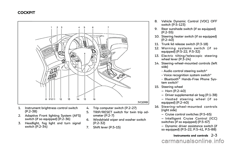
JVC1098X
1. Instrument brightness control switch(P.2-38)
2. Adaptive Front lighting System (AFS) switch (if so equipped) (P.2-36)
3. Headlight, fog light and turn signal switch (P.2-34) 4. Trip computer switch (P.2-27)
5. TRIP/RESET switch for twin trip od-
ometer (P.2-7)
6. Windshield wiper and washer switch (P.2-32)
7. Shift lever (P.5-15) 8. Vehicle Dynamic Control (VDC) OFF
switch (P.5-123)
9. Rear sunshade switch (if so equipped) (P.2-55)
10. Steering heater switch (if so equipped) (P.2-40)
11. Trunk lid release switch (P.3-18)
12. Warning systems switch (if so equipped) (P.5-22, P.5-32)
13. Electric tilting/telescopic steering wheel lever (P.3-24)
14. Steering-wheel-mounted controls (left side)
- Audio control steering switch*
- Voice recognition system switch*
- Bluetooth
®Hands-Free Phone Sys-
tem switch*
15. Steering wheel — Horn (P.2-40)
— Driver supplemental air bag (P.1-38)
— Heated steering wheel (if so
equipped) (P.2-40)
16. Steering-wheel-mounted controls (right side)
— Cruise control switches (P.5-65)
— Intelligent Cruise Control (ICC)
switches (if so equipped) (P.5-67)
— Dynamic driver assistance switch (if
so equipped) (P.5-22, P.5-41, P.5-88)
Instruments and controls2-3
COCKPIT
Page 90 of 458

WARNING
.If the light does not illuminate with
the ignition switch pushed ON, have
the vehicle checked as soon as possi-
ble. It is recommended you visit an
INFINITI retailer for this service.
. If the light illuminates while driving,
avoid sudden steering maneuvers or
abrupt braking, reduce vehicle speed,
pull off the road to a safe location
and stop the vehicle as soon as
possible. Driving with under-inflated
tires may permanently damage the
tires and increase the likelihood of
tire failure. Serious vehicle damage
could occur and may lead to an
accident and could result in serious
personal injury. Check the tire pres-
sure for all four tires. Adjust the tire
pressure to the recommended COLD
tire pressure shown on the Tire and
Loading Information label to turn the
low tire pressure warning light OFF.
If the light still illuminates while
driving after adjusting the tire pres-
sure, a tire may be flat or the TPMS
may be malfunctioning. If you have a
flat tire, replace it with a spare tire as
soon as possible. If no tire is flat and
all tires are properly inflated, have the vehicle checked. It is recom-
mended you visit an INFINITI retailer
for this service.
. Since the spare tire is not equipped
with the TPMS, when a spare tire is
mounted or a wheel is replaced, the
TPMS will not function and the low
tire pressure warning light will flash
for approximately 1 minute. The light
will remain on after the 1 minute.
Have your tires replaced and/or
TPMS system reset as soon as pos-
sible. It is recommended you visit an
INFINITI retailer for these services.
. Replacing tires with those not origin-
ally specified by INFINITI could affect
the proper operation of the TPMS.
CAUTION
.The TPMS is not a substitute for the
regular tire pressure check. Be sure to
check the tire pressure regularly.
. If the vehicle is being driven at speeds
of less than 16 MPH (25 km/h), the
TPMS may not operate correctly.
. Be sure to install the specified size of
tires to the four wheels correctly.
Master warning light
When the ignition switch is in the ON
position, the master warning light illumi-
nates if any of the following are displayed on
the vehicle information display:
.No key warning
. Low fuel warning
. Low washer fluid warning
. Parking brake release warning
. Door/trunk open warning
. Loose fuel cap warning
. Check tire pressure warning
. Intelligent Key system warning
. Headlight warning
. Front radar obstruction warning (if so
equipped)
. Back-up Collision Intervention (BCI) not
available warning (if so equipped)
. Back-up Collision Intervention (BCI) mal-
function warning (if so equipped)
See “Vehicle information display” (P.2-20).
Seat belt warning light and
chime
The light and chime remind you to fasten
seat belts. The light illuminates whenever
the ignition switch is pushed to the ON
position, and will remain illuminated until the
Instruments and controls2-15
Page 97 of 458
2-22Instruments and controls
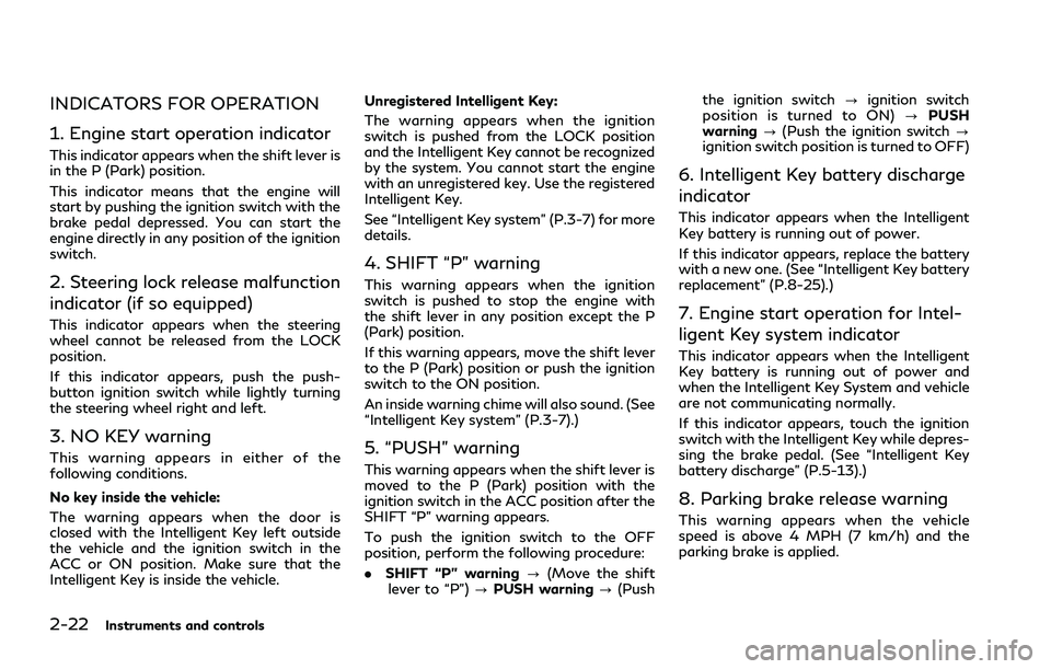
INDICATORS FOR OPERATION
1. Engine start operation indicator
This indicator appears when the shift lever is
in the P (Park) position.
This indicator means that the engine will
start by pushing the ignition switch with the
brake pedal depressed. You can start the
engine directly in any position of the ignition
switch.
2. Steering lock release malfunction
indicator (if so equipped)
This indicator appears when the steering
wheel cannot be released from the LOCK
position.
If this indicator appears, push the push-
button ignition switch while lightly turning
the steering wheel right and left.
3. NO KEY warning
This warning appears in either of the
following conditions.
No key inside the vehicle:
The warning appears when the door is
closed with the Intelligent Key left outside
the vehicle and the ignition switch in the
ACC or ON position. Make sure that the
Intelligent Key is inside the vehicle.Unregistered Intelligent Key:
The warning appears when the ignition
switch is pushed from the LOCK position
and the Intelligent Key cannot be recognized
by the system. You cannot start the engine
with an unregistered key. Use the registered
Intelligent Key.
See “Intelligent Key system” (P.3-7) for more
details.
4. SHIFT “P” warning
This warning appears when the ignition
switch is pushed to stop the engine with
the shift lever in any position except the P
(Park) position.
If this warning appears, move the shift lever
to the P (Park) position or push the ignition
switch to the ON position.
An inside warning chime will also sound. (See
“Intelligent Key system” (P.3-7).)
5. “PUSH” warning
This warning appears when the shift lever is
moved to the P (Park) position with the
ignition switch in the ACC position after the
SHIFT “P” warning appears.
To push the ignition switch to the OFF
position, perform the following procedure:
. SHIFT “P” warning ?(Move the shift
lever to “P”) ?PUSH warning ?(Push the ignition switch
?ignition switch
position is turned to ON) ?PUSH
warning ?(Push the ignition switch ?
ignition switch position is turned to OFF)
6. Intelligent Key battery discharge
indicator
This indicator appears when the Intelligent
Key battery is running out of power.
If this indicator appears, replace the battery
with a new one. (See “Intelligent Key battery
replacement” (P.8-25).)
7. Engine start operation for Intel-
ligent Key system indicator
This indicator appears when the Intelligent
Key battery is running out of power and
when the Intelligent Key System and vehicle
are not communicating normally.
If this indicator appears, touch the ignition
switch with the Intelligent Key while depres-
sing the brake pedal. (See “Intelligent Key
battery discharge” (P.5-13).)
8. Parking brake release warning
This warning appears when the vehicle
speed is above 4 MPH (7 km/h) and the
parking brake is applied.
Page 98 of 458
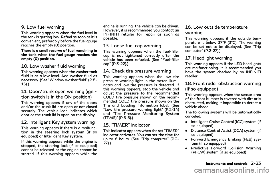
9. Low fuel warning
This warning appears when the fuel level in
the tank is getting low. Refuel as soon as it is
convenient, preferably before the fuel gauge
reaches the empty (0) position.
There is a small reserve of fuel remaining in
the tank when the fuel gauge reaches the
empty (0) position.
10. Low washer fluid warning
This warning appears when the washer tank
fluid is at a low level. Add washer fluid as
necessary. (See “Window washer fluid” (P.8-
15).)
11. Door/trunk open warning (igni-
tion switch is in the ON position)
This warning appears if any of the doors
and/or the trunk lid are open or not closed
securely. The vehicle icon indicates which
door or the trunk lid is open on the display.
12. Intelligent Key system warning
This warning appears if there is a malfunc-
tion in the steering lock system (if so
equipped) or Intelligent Key system.
If this warning appears while the engine is
stopped, the steering lock (if so equipped)
cannot be released or the engine cannot be
started. If this warning appears while theengine is running, the vehicle can be driven.
However, it is recommended you contact an
INFINITI retailer for repair as soon as
possible.
13. Loose fuel cap warning
This warning appears when the fuel-filler
cap is not tightened correctly after the
vehicle has been refueled. (See “Fuel-filler
cap” (P.3-22).)
14. Check tire pressure warning
This warning appears when the low tire
pressure warning light in the meter illumi-
nates and low tire pressure is detected. If
this warning appears, stop the vehicle and
adjust the pressure to the recommended
COLD tire pressure shown on the recom-
mended COLD tire pressure shown on the
Tire and Loading Information label. (See
“Low tire pressure warning light” (P.2-14)
and “Tire Pressure Monitoring System
(TPMS)” (P.5-5).)
15. “TIMER” indicator
This indicator appears when the set “TIMER”
indicator activates. You can set the time for
up to 6 hours. (See “Trip computer” (P.2-
27).)
16. Low outside temperature
warning
This warning appears if the outside tem-
perature is below 37°F (3°C). The warning
can be set not to be displayed. (See “Trip
computer” (P.2-27).)
17. Headlight warning
This warning appears if the LED headlights
are malfunctioning. It is recommended you
have the system checked by an INFINITI
retailer.
18. Front radar obstruction warning
(if so equipped)
This warning appears when the sensor area
of the front bumper is covered with dirt or is
obstructed, making it impossible to detect a
vehicle ahead.
The following systems will be automatically
canceled.
.
Intelligent Cruise Control (ICC) system (if
so equipped)
. Distance Control Assist (DCA) system (if
so equipped)
. Forward Emergency Braking (FEB) sys-
tem (if so equipped)
. Predictive Forward Collision Warning
(PFCW) system (if so equipped)
Instruments and controls2-23
Page 111 of 458
2-36Instruments and controls
SIC3269
Headlight beam select
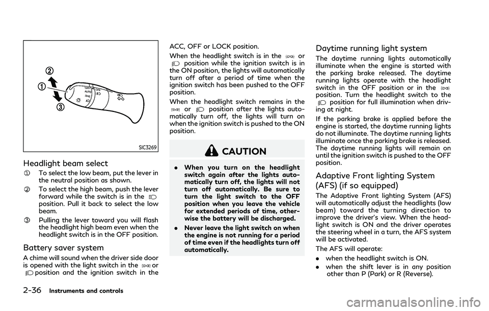
To select the low beam, put the lever in
the neutral position as shown.
To select the high beam, push the lever
forward while the switch is in the
position. Pull it back to select the low
beam.
Pulling the lever toward you will flash
the headlight high beam even when the
headlight switch is in the OFF position.
Battery saver system
A chime will sound when the driver side door
is opened with the light switch in theorposition and the ignition switch in theACC, OFF or LOCK position.
When the headlight switch is in the
orposition while the ignition switch is in
the ON position, the lights will automatically
turn off after a period of time when the
ignition switch has been pushed to the OFF
position.
When the headlight switch remains in the
orposition after the lights auto-
matically turn off, the lights will turn on
when the ignition switch is pushed to the ON
position.
CAUTION
. When you turn on the headlight
switch again after the lights auto-
matically turn off, the lights will not
turn off automatically. Be sure to
turn the light switch to the OFF
position when you leave the vehicle
for extended periods of time, other-
wise the battery will be discharged.
. Never leave the light switch on when
the engine is not running for a period
of time even if the headlights turn off
automatically.
Daytime running light system
The daytime running lights automatically
illuminate when the engine is started with
the parking brake released. The daytime
running lights operate with the headlight
switch in the OFF position or in the
position. Turn the headlight switch to theposition for full illumination when driv-
ing at night.
If the parking brake is applied before the
engine is started, the daytime running lights
do not illuminate. The daytime running lights
illuminate once the parking brake is released.
The daytime running lights will remain on
until the ignition switch is pushed to the OFF
position.
Adaptive Front lighting System
(AFS) (if so equipped)
The Adaptive Front lighting System (AFS)
will automatically adjust the headlights (low
beam) toward the turning direction to
improve the driver’s view. When the head-
light switch is ON and the driver operates
the steering wheel in a turn, the AFS system
will be activated.
The AFS will operate:
. when the headlight switch is ON.
. when the shift lever is in any position
other than P (Park) or R (Reverse).
Page 112 of 458

.when the vehicle is driven at above 3
MPH (5 km/h) for the left-side head-
light. Note that the right-side low beam
headlight will swivel but the left side will
not swivel when the vehicle is below 3
MPH (5 km/h) and the steering wheel is
turned.
SIC4333
To turn the AFS off, push the AFS switch.
(The AFS OFF indicator light will illuminate.)
Push the switch again to turn the system on
again.
AFS will also adjust the headlight to a proper
axis automatically, depending on the number
of occupants in the vehicle, the load the
vehicle is carrying and the road conditions.
If the AFS OFF indicator light blinks after
the ignition switch has been placed in the
ON position, this may indicate that the AFS
is not functioning properly. Have the system
checked. It is recommended you visit an
INFINITI retailer for this service. When the
engine is started, the headlights will vibrate
to check the system condition. This is not a malfunction.
Instruments and controls2-37
Page 115 of 458

2-40Instruments and controls
JVI0395X
The heated steering wheel system is de-
signed to operate only when the surface
temperature of the steering wheel is below
68°F (20°C).
Push the heated steering wheel switch to
warm the steering wheel after the engine
starts. The indicator light
on the switch
will illuminate.
If the surface temperature of the steering
wheel is below 68°F (20°C), the system will
heat the steering wheel and cycle off and on
to maintain a temperature above 68°F
(20°C). The indicator light will remain on as
long as the system is on.
Push the switch again to turn the heated
steering wheel system off manually. The indicator light will turn off.
NOTE:
If the surface temperature of the steering
wheel is above 68°F (20°C) when the switch
is turned on, the system will not heat the
steering wheel. This is not a malfunction.
SIC4332
To sound the horn, push the center pad area
of the steering wheel.
WARNING
Do not disassemble the horn. Doing so
could affect proper operation of the
supplemental front air bag system. Tam-
pering with the supplemental front air
bag system may result in serious perso-
nal injury.
HEATED STEERING WHEEL (if so
equipped)
HORN
Page 140 of 458
3 Pre-driving checks and adjustments
Keys ........................................................................\
.............. 3-2Intelligent Key .............................................................. 3-2
Valet hand-off ............................................................. 3-3
Doors ........................................................................\
............ 3-4 Locking with mechanical key ................................... 3-4
Opening and closing windows with the
mechanical key ............................................................. 3-4
Locking with inside lock knob ................................. 3-5
Rear door auto closure (if so equipped) ............... 3-5
Locking with power door lock switch ................... 3-5
Automatic door locks ................................................. 3-6
Child safety rear door lock ....................................... 3-6
Intelligent Key system ...................................................... 3-7
Intelligent Key operating range ............................... 3-8
Door locks/unlocks precaution .............................. 3-9
Intelligent Key operation ......................................... 3-10
Battery saver system ............................................... 3-11
Warning signals ......................................................... 3-12
Troubleshooting guide ............................................. 3-13
Remote keyless entry system ...................................... 3-14
How to use remote keyless entry system .......... 3-14
Hood ........................................................................\
........... 3-17 Trunk lid ........................................................................\
.... 3-18
Trunk lid release switch ......................................... 3-18
Trunk open request switch ................................... 3-19
Opening with key .................................................... 3-19
Trunk button ............................................................. 3-19
Trunk release power cancel switch ................... 3-20
Auto closure ............................................................. 3-20
Interior trunk lid release ........................................ 3-21
Fuel-filler door ................................................................ 3-22 Opening the fuel-filler door ................................. 3-22
Fuel-filler cap ........................................................... 3-22
Tilt/telescopic steering ................................................. 3-24 Electric operation .................................................... 3-24
Sun visors ........................................................................\
. 3-25
Mirrors ........................................................................\
...... 3-25 Inside mirror .............................................................. 3-25
Outside mirrors ........................................................ 3-26
Vanity mirror ............................................................ 3-28
Automatic drive positioner .......................................... 3-28 Entry/exit function ................................................. 3-28
Memory storage ...................................................... 3-29
Setting memory function ..................................... 3-30
System operation ................................................... 3-30