display INFINITI Q70 HYBRID 2014 Owner's Manual
[x] Cancel search | Manufacturer: INFINITI, Model Year: 2014, Model line: Q70 HYBRID, Model: INFINITI Q70 HYBRID 2014Pages: 522, PDF Size: 4.02 MB
Page 12 of 522

RAPID ACCELERATION
The vehicle is accelerated using both the
gasoline engine and the electric motor
depending on the available Li-ion battery
charge.
DECELERATION AND BRAKING
The Li-ion battery is charged by the electric
motor that changes the energy of the
rotating wheels into electric power. See
“Regenerative brake”(P.Hybrid System-8).
STOPPING
The gasoline engine may stop running to
save fuel depending on the available Li-ion
battery charge. The INFINITI Direct Response Hybrid
®
System monitors the status of power being
sent to the electric motor and the Lithium
ion (Li-ion) battery state of charge. The
status is shown on the assist charge gauge
in the meter and the energy flow/remain-
ing Li-ion battery charge in the dot matrix
display. System status can also be shown
on the navigation system display (if so
equipped) when the screen is in the energy
flow mode or energy/fuel history mode.
JVO0001X
ASSIST CHARGE GAUGE
This meter displays the actual electric
motor power consumption and the char-
ging power to the Li-ion battery.
For additional information, See
“Assist
charge gauge” (P.2-8).
ENERGY FLOW (models with navi-
gation system)
When you use this system, make sure the
hybrid system is in the READY to drive
mode. See“Operation of the hybrid
system” (P.Hybrid System-4).
Hybrid System OverviewHybrid System-5
ENERGY MONITORS
Page 13 of 522

Hybrid System-6Hybrid System Overview
If you use the system with the hybrid
system off (ignition switch placed in the
ACC position) for a long time, it will
discharge the 12-volt battery power, and
the hybrid system will not start.
Energy Flow for various operating modes
can be displayed on the navigation system
monitor.
JVH0034M
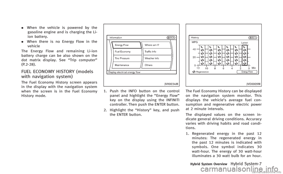
Push the INFO button on the control panel
and highlight the“Energy Flow”key on the
display using the INFINITI controller then
push the ENTER button.
JVO0008M
This is an example of the Energy Flow
display. The Energy Flow display changes,
depending on the following operating
conditions. The graphic indicates the
amount of power in the Li-ion battery.
The following are displayed on the Energy
Flow screen.
. When the vehicle is powered only by
the electric motor or gasoline engine.
. When the vehicle is powered by both
the electric motor and the gasoline
engine.
. When the vehicle is charging the Li-ion
battery with the regenerative brake and
gasoline engine.
Page 14 of 522

.When the vehicle is powered by the
gasoline engine and is charging the Li-
ion battery.
. When there is no Energy Flow in the
vehicle
The Energy Flow and remaining Li-ion
battery charge can be also shown on the
dot matrix display. See “Trip computer”
(P.2-28).
FUEL ECONOMY HISTORY (models
with navigation system)
The Fuel Economy History screen appears
in the display with the navigation system
when the screen is in the Fuel Economy
History mode.JVH0034M
1. Push the INFO button on the control
panel and highlight the “Energy Flow”
key on the display using the INFINITI
controller. Then push the ENTER button.
2. Highlight the “History”key, and push
the ENTER button.
JVO0009M
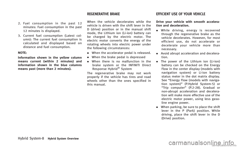
The Fuel Economy History can be displayed
on the navigation system monitor. This
displays the vehicle’s average fuel con-
sumption and regenerative electric power
at 2 minute intervals.
The displayed values on the screen in-
dicate general driving conditions. Accuracy
varies with driving habits and road condi-
tions.
1. Regenerated energy in the past 12 minutes: The regenerated energy in
the past 12 minutes is indicated with
symbols. One symbol indicates 30
watt-hour. The energy of 30 watt-hour
illuminates a 30 watt bulb for an hour.
Hybrid System OverviewHybrid System-7
Page 15 of 522

Hybrid System-8Hybrid System Overview
2. Fuel consumption in the past 12minutes: Fuel consumption in the past
12 minutes is displayed.
3. Current fuel consumption (Latest col- umn): The current fuel consumption is
calculated and displayed based on
distance and fuel consumption.
NOTE:
Information shown in the yellow column
means current (within 2 minutes) and
information shown in the blue columns
means past (more than 2 minutes). When the vehicle decelerates while the
vehicle is driven with the shift lever in the
D (drive) position or in the manual shift
mode, the Lithium ion (Li-ion) battery can
be charged by the electric motor. The
electric motor converts the energy of the
rotating wheels into electric power under
the following circumstances:
.
When the accelerator pedal is released.
. When the brake pedal is depressed
. When there is no malfunction in the
brake system or the INFINITI Direct
Response Hybrid
®System
The regenerative brake may not work
properly if the vehicle has tires and road
wheels other than the ones specified in
this manual. Drive your vehicle with smooth accelera-
tion and deceleration.
.
While driving, energy is recovered
through the regenerative brake as the
vehicle decelerates. However, for most
efficient use, do not accelerate or
decelerate your vehicle more than
necessary.
. Avoid abrupt acceleration and decelera-
tion.
. The power of the Lithium ion (Li-ion)
battery can be checked on the Energy
Flow in the center display (models with
navigation system) or Li-ion battery
status meter in the dot matrix display.
See “Energy Flow (models with naviga-
tion system)” (P.Hybrid System-5) or
“Trip computer” (P.2-28). Gradual or
non-abrupt acceleration and decelera-
tion will make more effective use of the
electric motor power, using less gaso-
line engine power.
. When parking, be sure to place the shift
lever in the P (Park) position. While
driving, place the shift lever in the D
(Drive) position.
REGENERATIVE BRAKE EFFICIENT USE OF YOUR VEHICLE
Page 29 of 522

0-8Illustrated table of contents
JVO0132X
1. Side ventilator (P.4-33)
2. Meters and gauges (P.2-6)
3. Hazard warning flasher switch (P.6-2)
4. Rear window and outside mirrordefroster switch (P.2-37)
5. Center display (P.4-4)/Navigation sys- tem* (if so equipped)
6. Clock (P.2-49)
7. Center multi-function control panel —Navigation system* (if so
equipped) —
Vehicle information and setting
buttons (P.4-10)
— Bluetooth
®Hands-Free Phone Sys-
tem (P.4-84, P.4-95)
— Audio system (P.4-48)
8. Automatic climate control system (P.4-34)/Forest Air
®system (P.4-34)
9. Center ventilator (P.4-33)
10. Audio system (P.4-48)
11. Front passenger supplemental air bag (P.1-37)
12. Hood release handle (P.3-16)
13. Fuse box cover (P.8-24)
14. Parking brake —Parking (P.5-18)
15. Push-button ignition switch (P.5-9)
16. Front passenger air bag status light (P.1-44)
17. Climate controlled seat switch (if so equipped) (P.2-46)/Seat heater switch
(if so equipped) (P.2-44)
18. Drive mode select switch (P.5-18)
19. Cigarette lighter and ashtray (P.2-50)
20. Glove box lid release handle (P.2-52)
21. Trunk release power cancel switch (P.3-18)
*: Refer to the separate Navigation System Owner’s Manual.
INSTRUMENT PANEL
Page 30 of 522

JVI0200X
1. Tachometer (P.2-8)
2. Warning/Indicator lights (P.2-10)
3. Speedometer (P.2-7)
4. Assist charge gauge (P.2-8)
5. Dot matrix liquid crystal display/Odometer/twin trip odometer (P.2-21)
6. Fuel gauge (P.2-8)
Illustrated table of contents0-9
METERS AND GAUGES
Page 83 of 522

1-50Safety—Seats, seat belts and supplemental restraint system
SSS1016
SUPPLEMENTAL AIR BAG WARNING
LABELS
Warning labels about the supplemental
front-impact air bag systems are placed in
the vehicle as shown in the illustration.
SRS air bag
The warning labels*1are located on the
surface of the sun visors.
SPA1097
SUPPLEMENTAL AIR BAG WARNING
LIGHT
The supplemental air bag warning light,
displayingin the instrument panel,
monitors the circuits for the air bag
systems, pretensioners and all related
wiring.
When the ignition switch is in the ON
position, the supplemental air bag warning
light illuminates for about 7 seconds and
then turns off. This means the SRS air bag
systems are operational.
If any of the following conditions occur, the
air bags and/or pretensioner systems need servicing:
.
The supplemental air bag warning light
remains on after approximately 7 sec-
onds.
. The supplemental air bag warning light
flashes intermittently.
. The supplemental air bag warning light
does not come on at all.
Under these conditions, the air bags and/
or pretensioner systems may not operate
properly. They must be checked and
repaired. Take your vehicle to the nearest
INFINITI retailer.
WARNING
If the supplemental air bag warning light is
on, it could mean that the air bags and/or
pretensioner systems will not operate in an
accident. To help avoid injury to yourself or
others, have your vehicle checked by an
INFINITI retailer as soon as possible.
Page 86 of 522

2 Instruments and controls
Cockpit................................................................ 2-3
Instrument panel ................................................. 2-5
Meters and gauges .............................................. 2-6
Speedometer and odometer ............................ 2-7
Tachometer...................................................... 2-8
Assist charge gauge ........................................ 2-8
Fuel gauge ...................................................... 2-8
Warning/indicator lights and
audible reminders ............................................. 2-10 Checking bulbs.............................................. 2-11
Warning lights ............................................... 2-11
Indicator lights .............................................. 2-17
Audible reminders ......................................... 2-20
Dot matrix liquid crystal display ........................ 2-21 Operational indicators ................................... 2-23
Maintenance indicators ................................. 2-26
Trip computer ................................................ 2-28
Security systems ............................................... 2-32 Vehicle Security System ................................ 2-32
INFINITI Vehicle Immobilizer System .............. 2-34
Windshield wiper and washer switch ................. 2-35 Rain-sensing auto wiper system .................... 2-36
Rear window and outside mirror
defroster switch ................................................. 2-37
Headlight and turn signal switch ....................... 2-38 Xenon headlights......................................... 2-38
Headlight switch .......................................... 2-38
Turn signal switch........................................ 2-43
Fog light switch ........................................... 2-43
Heated steering wheel (if so equipped) ............. 2-43
Horn ................................................................. 2-44
Heated seats (if so equipped) ........................... 2-44
Climate controlled seats (if so equipped) .......... 2-46
Warning systems switch (if so equipped) .......... 2-47
Intelligent Brake Assist (IBA) OFF switch
(if so equipped) ................................................ 2-47
Vehicle Dynamic Control (VDC) OFF switch ......... 2-48
Clock................................................................. 2-49
Adjusting the time ....................................... 2-49
Power outlet ..................................................... 2-49
Cigarette lighter and ashtrays ........................... 2-50
Front............................................................ 2-50
Rear............................................................. 2-50
Storage ............................................................. 2-51 Cup holders ................................................. 2-51
Sunglasses holder ...................................... 2-52
Glove box .................................................... 2-52
Console box................................................. 2-53
Card holder.................................................. 2-53
Rear pocket ................................................. 2-54
Page 90 of 522

JVO0132X
1. Side ventilator (P.4-33)
2. Meters and gauges (P.2-6)
3. Hazard warning flasher switch (P.6-2)
4. Rear window and outside mirrordefroster switch (P.2-37)
5. Center display (P.4-4)/Navigation sys- tem* (if so equipped)
6. Clock (P.2-49)
7. Center multi-function control panel —Navigation system* (if so
equipped) —
Vehicle information and setting
buttons (P.4-10)
— Bluetooth
®Hands-Free Phone Sys-
tem (P.4-84, P.4-95)
— Audio system (P.4-48)
8. Automatic climate control system (P.4-34)/Forest Air
®system* (P.4-34)
9. Center ventilator (P.4-33)
10. Audio system (P.4-48)
11. Front passenger supplemental air bag (P.1-37)
12. Hood release handle (P.3-16)
13. Fuse box cover (P.8-24)
14. Parking brake —Parking (P.5-18)
15. Push-button ignition switch (P.5-9)
16. Front passenger air bag status light (P.1-44)
17. Climate controlled seat switch (if so equipped) (P.2-46)/Seat heater switch
(if so equipped) (P.2-44)
18. Drive mode select switch (P.5-18)
19. Cigarette lighter and ashtray (P.2-50)
20. Glove box lid release handle (P.2-52)
21. Trunk release power cancel switch (P.3-18)
*: Refer to the separate Navigation System Owner’s Manual.
Instruments and controls2-5
INSTRUMENT PANEL
Page 91 of 522

2-6Instruments and controls
JVI0200X
1. Tachometer (P.2-8)
2. Warning/Indicator lights (P.2-10)
3. Speedometer (P.2-7)
4. Assist charge gauge (P.2-8)5. Dot matrix liquid crystal display/
Odometer/twin trip odometer
(P.2-21)
6. Fuel gauge (P.2-8) *: The needle indicators in the speed-
ometer, tachometer, assist charge gauge
and fuel gauge may move slightly after the
ignition switch is pushed to the LOCK
position. This is not a malfunction.
CAUTION
.
For cleaning, use a soft cloth, dampened
with water. Never use a rough cloth,
alcohol, benzine, thinner or any kind of
solvent or paper towel with a chemical
cleaning agent. They will scratch or
cause discoloration to the lens.
. Do not spray any liquid such as water on
the meter lens. Spraying liquid may
cause the system to malfunction.
METERS AND GAUGES