transmission INFINITI Q70 HYBRID 2014 Owner's Manual
[x] Cancel search | Manufacturer: INFINITI, Model Year: 2014, Model line: Q70 HYBRID, Model: INFINITI Q70 HYBRID 2014Pages: 522, PDF Size: 4.02 MB
Page 11 of 522
Hybrid System-4Hybrid System Overview
The emergency shut-off system is activated
and the high-voltage system automatically
turns off in the following conditions:
.Front and side collisions in which the
air bags are deployed.
. Certain rear collisions.
. Certain INFINITI Direct Response Hy-
brid
®System malfunctions
For the above collisions and the certain
hybrid system malfunctions, the READY to
drive indicator light will turn off. See
“Warning/indicator lights and audible re-
minders” (P.2-10).
The emergency shut-off activates for the
above collisions to minimize risk of an
event that could cause injury or an
accident. If the emergency shut-off system
activates, the hybrid system may not
switched to READY to drive position,
contact an INFINITI retailer. Even if the
ignition switch is switched to READY to
drive position, the system may shut-off
suddenly. Therefore, drive cautiously to the
nearest INFINITI retailer or contact an
INFINITI retailer as soon as possible. To start the INFINITI Direct Response
Hybrid
®System:
1. Depress the brake pedal and place the ignition switch in the ON position when
the transmission is in the P (Park) or N
(Neutral) position (P is recommended).
(For more details, see “Push-button
ignition switch” (P.5-9).)
2. The READY to drive indicator light
flashes, then turns illuminated. (The
hybrid system switched to the READY to
drive mode when the indicator light
illuminates.)
When the READY to drive indicator light
illuminates, the vehicle can be
driven, even if the gasoline engine is not
running.
NOTE:
The gasoline engine starts and stops
automatically. It may stop during low
speed driving, deceleration or when the
vehicle is stopped.
The gasoline engine may automatically
run in the following conditions:
. The level of remaining charge in the
Lithium ion (Li-ion) battery is low. The
engine runs to charge the Li-ion
battery and to provide power to the drive the vehicle.
. The temperature of the engine coolant
is low.
. Based on driving conditions.
. The shift lever is shifted to the P (Park)
position, the driver’ s seat belt is
released and the driver’s side door is
then opened.
The hybrid system operates as follows
based on driving conditions and the Li-ion
battery charge.
STARTING AND SLOW SPEED DRIV-
ING
The vehicle is driven by the electric motor
depending on the available Li-ion battery
charge.
MEDIUM OR HIGH SPEED DRIVING
The system automatically controls the
gasoline engine and electric motor in order
to obtain the optimum fuel mileage and
performance, depending on the driving
situation and available Li-ion battery
charge.
When the remaining battery level is low,
the Li-ion battery is charged by the electric
motor that is driven to generate electric
power while the vehicle is driving.
EMERGENCY SHUT-OFF SYSTEM OPERATION OF THE HYBRID SYSTEM
Page 18 of 522

tion. High voltage harnesses are orange.
The system can be hot while and after
starting. Be careful of both the high voltage
and the high temperature.
HYBRID VEHICLE CHARACTERISTICS
WARNING
.When you leave your vehicle, be sure to
place the ignition switch in the OFF
position.
. Be sure to put the transmission in the P
(Park) position because the vehicle can
move when the READY to drive indicator
light is on even if the gasoline engine is
not running. When the READY to drive
indicator light is on, do not leave your
vehicle in a shift position other than the
P (Park) position. The vehicle will creep
and start abruptly if the accelerator
pedal is depressed by mistake. This
may cause serious injury or death.
CAUTION
If the vehicle is parked for a long period of
time, the battery discharges gradually. To avoid this occurrence, drive the vehicle for
approximately 30 minutes at least once
every two to three months. Otherwise, the
Lithium ion (Li-ion) battery may be da-
maged. If the Li-ion battery is completely
discharged and the hybrid system cannot be
activated, contact an INFINITI retailer.
High voltage parts and harnesses on the
hybrid vehicles emit approximately the
same amount of electromagnetic waves
as the conventional gasoline-powered ve-
hicles or home electronic appliances de-
spite of their electromagnetic shieldings.
Unwanted noise may occur in the reception
of a mobile two-way radio.
Charging the Li-ion battery while driving is
important. The vehicle cannot run if the Li-
ion battery is discharged. In the N (Neutral)
position, the Li-ion battery does not
recharge. Leaving the transmission in the
N (Neutral) position for an extended period
of time may discharge the Li-ion battery.
The Li-ion battery recharges when the shift
lever is in any position other than N
(Neutral).
JVO0019X
An air vent*Ais located on the rear parcel
shelf to cool the Li-ion battery. If the vent is
covered, the battery will overheat resulting
in reduced output performance of the
hybrid system. See “Lithium-ion (Li-ion)
battery air vent” (P.7-5).
Hybrid System OverviewHybrid System-11
Page 32 of 522
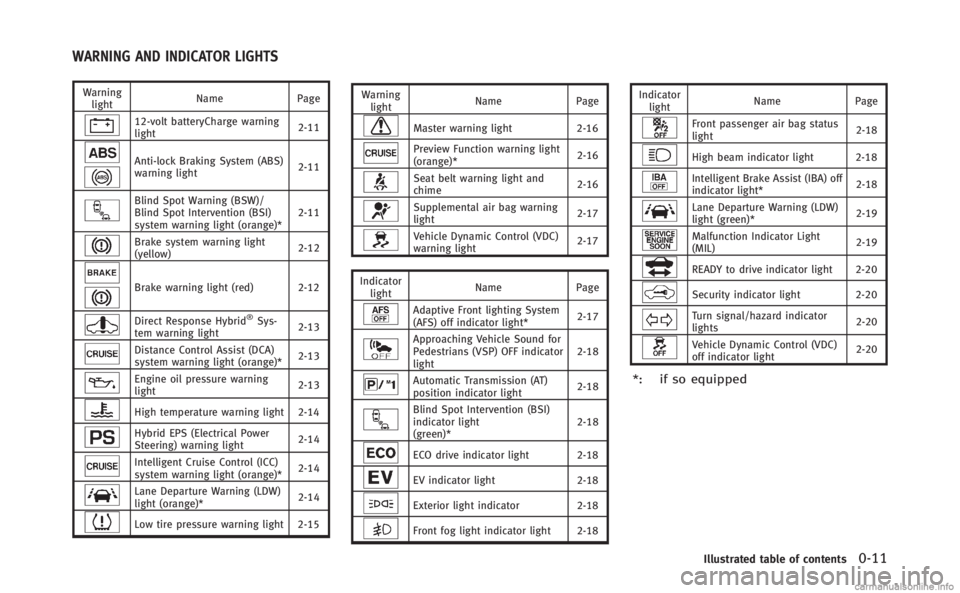
Warninglight Name
Page
12-volt batteryCharge warning
light 2-11
Anti-lock Braking System (ABS)
warning light2-11
Blind Spot Warning (BSW)/
Blind Spot Intervention (BSI)
system warning light (orange)*2-11
Brake system warning light
(yellow)
2-12
Brake warning light (red) 2-12
Direct Response Hybrid®Sys-
tem warning light 2-13
Distance Control Assist (DCA)
system warning light (orange)*
2-13
Engine oil pressure warning
light2-13
High temperature warning light 2-14
Hybrid EPS (Electrical Power
Steering) warning light2-14
Intelligent Cruise Control (ICC)
system warning light (orange)*2-14
Lane Departure Warning (LDW)
light (orange)*
2-14
Low tire pressure warning light 2-15 Warning
light Name
Page
Master warning light 2-16
Preview Function warning light
(orange)* 2-16
Seat belt warning light and
chime2-16
Supplemental air bag warning
light
2-17
Vehicle Dynamic Control (VDC)
warning light2-17
Indicator light Name
Page
Adaptive Front lighting System
(AFS) off indicator light* 2-17
Approaching Vehicle Sound for
Pedestrians (VSP) OFF indicator
light2-18
Automatic Transmission (AT)
position indicator light
2-18
Blind Spot Intervention (BSI)
indicator light
(green)*2-18
ECO drive indicator light 2-18
EV indicator light
2-18
Exterior light indicator2-18
Front fog light indicator light 2-18 Indicator
light Name
Page
Front passenger air bag status
light 2-18
High beam indicator light 2-18
Intelligent Brake Assist (IBA) off
indicator light*2-18
Lane Departure Warning (LDW)
light (green)*
2-19
Malfunction Indicator Light
(MIL)2-19
READY to drive indicator light 2-20
Security indicator light 2-20
Turn signal/hazard indicator
lights2-20
Vehicle Dynamic Control (VDC)
off indicator light2-20
*: if so equipped
Illustrated table of contents0-11
WARNING AND INDICATOR LIGHTS
Page 95 of 522
2-10Instruments and controls
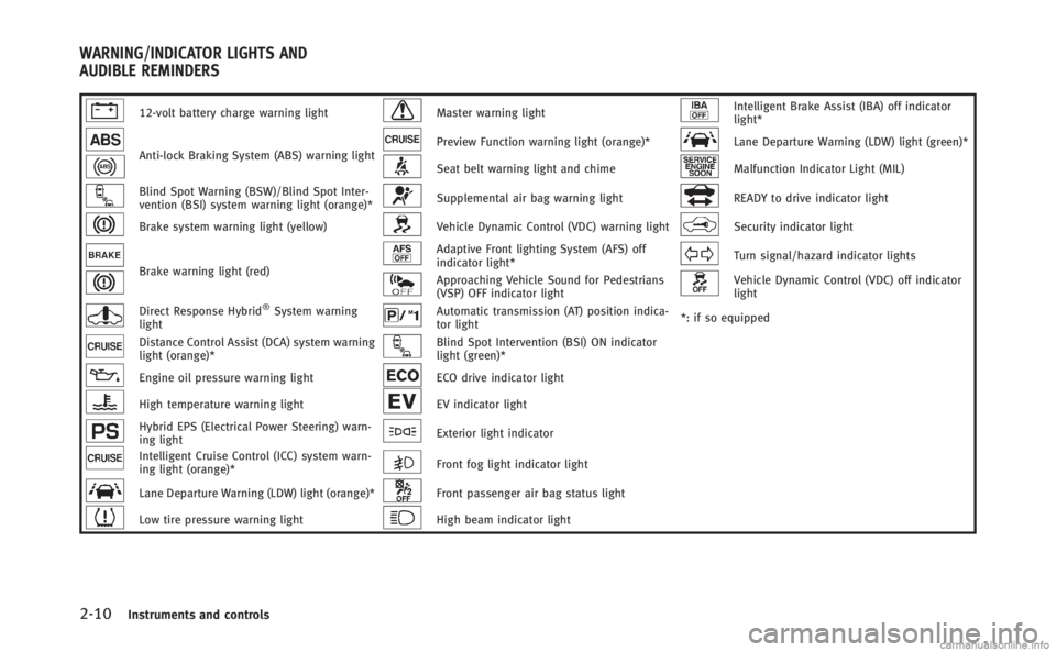
12-volt battery charge warning lightMaster warning lightIntelligent Brake Assist (IBA) off indicator
light*
Anti-lock Braking System (ABS) warning lightPreview Function warning light (orange)*Lane Departure Warning (LDW) light (green)*
Seat belt warning light and chimeMalfunction Indicator Light (MIL)
Blind Spot Warning (BSW)/Blind Spot Inter-
vention (BSI) system warning light (orange)*Supplemental air bag warning lightREADY to drive indicator light
Brake system warning light (yellow)Vehicle Dynamic Control (VDC) warning lightSecurity indicator light
Brake warning light (red)
Adaptive Front lighting System (AFS) off
indicator light*Turn signal/hazard indicator lights
Approaching Vehicle Sound for Pedestrians
(VSP) OFF indicator lightVehicle Dynamic Control (VDC) off indicator
light
Direct Response Hybrid®System warning
lightAutomatic transmission (AT) position indica-
tor light *: if so equipped
Distance Control Assist (DCA) system warning
light (orange)*Blind Spot Intervention (BSI) ON indicator
light (green)*
Engine oil pressure warning lightECO drive indicator light
High temperature warning lightEV indicator light
Hybrid EPS (Electrical Power Steering) warn-
ing lightExterior light indicator
Intelligent Cruise Control (ICC) system warn-
ing light (orange)*Front fog light indicator light
Lane Departure Warning (LDW) light (orange)*Front passenger air bag status light
Low tire pressure warning lightHigh beam indicator light
WARNING/INDICATOR LIGHTS AND
AUDIBLE REMINDERS
Page 103 of 522
2-18Instruments and controls
(P.2-40).
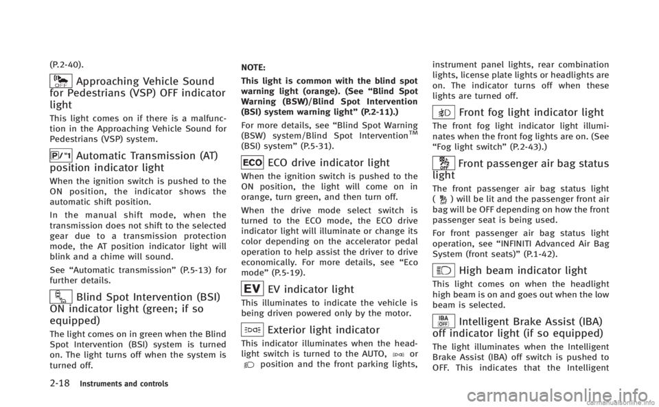
Approaching Vehicle Sound
for Pedestrians (VSP) OFF indicator
light
This light comes on if there is a malfunc-
tion in the Approaching Vehicle Sound for
Pedestrians (VSP) system.
Automatic Transmission (AT)
position indicator light
When the ignition switch is pushed to the
ON position, the indicator shows the
automatic shift position.
In the manual shift mode, when the
transmission does not shift to the selected
gear due to a transmission protection
mode, the AT position indicator light will
blink and a chime will sound.
See “Automatic transmission” (P.5-13) for
further details.
Blind Spot Intervention (BSI)
ON indicator light (green; if so
equipped)
The light comes on in green when the Blind
Spot Intervention (BSI) system is turned
on. The light turns off when the system is
turned off. NOTE:
This light is common with the blind spot
warning light (orange). (See
“Blind Spot
Warning (BSW)/Blind Spot Intervention
(BSI) system warning light” (P.2-11).)
For more details, see “Blind Spot Warning
(BSW) system/Blind Spot Intervention
TM
(BSI) system” (P.5-31).
ECO drive indicator light
When the ignition switch is pushed to the
ON position, the light will come on in
orange, turn green, and then turn off.
When the drive mode select switch is
turned to the ECO mode, the ECO drive
indicator light will illuminate or change its
color depending on the accelerator pedal
operation to help assist the driver to drive
economically. For more details, see “Eco
mode” (P.5-19).
EV indicator light
This illuminates to indicate the vehicle is
being driven powered only by the motor.
Exterior light indicator
This indicator illuminates when the head-
light switch is turned to the AUTO,orposition and the front parking lights, instrument panel lights, rear combination
lights, license plate lights or headlights are
on. The indicator turns off when these
lights are turned off.
Front fog light indicator light
The front fog light indicator light illumi-
nates when the front fog lights are on. (See
“Fog light switch”
(P.2-43).)
Front passenger air bag status
light
The front passenger air bag status light
() will be lit and the passenger front air
bag will be OFF depending on how the front
passenger seat is being used.
For front passenger air bag status light
operation, see “INFINITI Advanced Air Bag
System (front seats)” (P.1-42).
High beam indicator light
This light comes on when the headlight
high beam is on and goes out when the low
beam is selected.
Intelligent Brake Assist (IBA)
off indicator light (if so equipped)
The light illuminates when the Intelligent
Brake Assist (IBA) off switch is pushed to
OFF. This indicates that the Intelligent
Page 106 of 522
motion. This scraping sound will first occur
only when the brake pedal is depressed.
After more wear of the brake pad, the
sound will always be heard even if the
brake pedal is not depressed. Have the
brakes checked as soon as possible if the
warning sound is heard.
JVI0199X
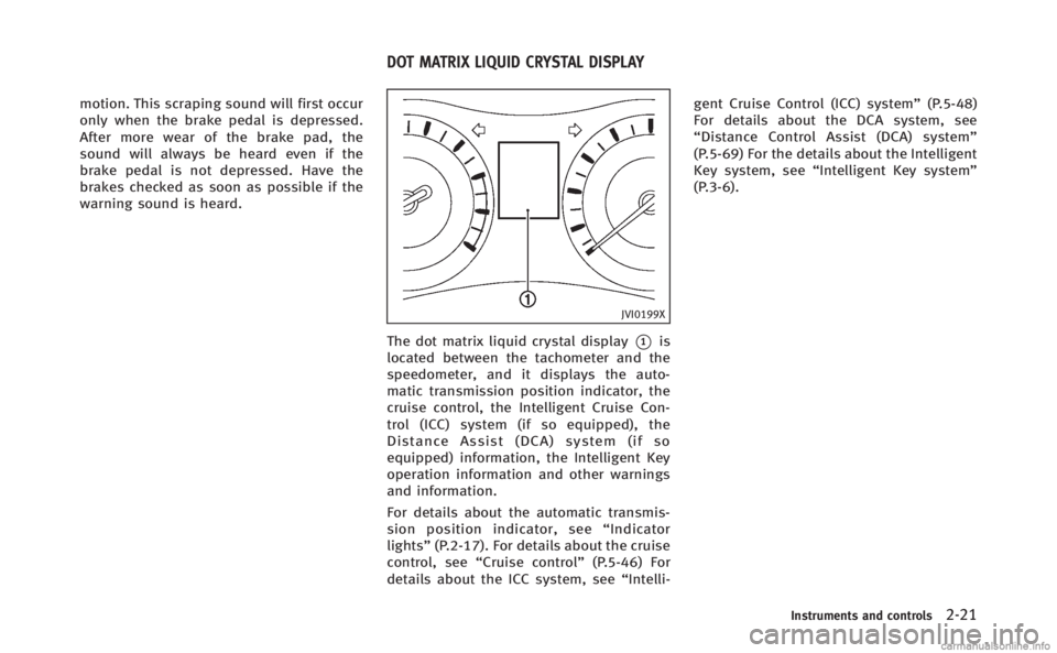
The dot matrix liquid crystal display*1is
located between the tachometer and the
speedometer, and it displays the auto-
matic transmission position indicator, the
cruise control, the Intelligent Cruise Con-
trol (ICC) system (if so equipped), the
Distance Assist (DCA) system (if so
equipped) information, the Intelligent Key
operation information and other warnings
and information.
For details about the automatic transmis-
sion position indicator, see “Indicator
lights” (P.2-17). For details about the cruise
control, see “Cruise control” (P.5-46) For
details about the ICC system, see “Intelli-gent Cruise Control (ICC) system”
(P.5-48)
For details about the DCA system, see
“ Distance Control Assist (DCA) system”
(P.5-69) For the details about the Intelligent
Key system, see “Intelligent Key system”
(P.3-6).
Instruments and controls2-21
DOT MATRIX LIQUID CRYSTAL DISPLAY
Page 110 of 522

16. Low outside temperature warn-
ing
This warning appears if the outside tem-
perature is below 378F(38C). The warning
can be set not to be displayed. (See “Trip
computer” (P.2-28).)
17. Hybrid system over heat warn-
ing
This warning appears when the tempera-
ture of the hybrid system is too high. Stop
the vehicle in a safe location as soon as
possible. Avoid quick starting or abrupt
acceleration. When the warning turns off,
the vehicle can be driven.
If the warning appears again soon after it
turns off, have the vehicle checked by an
INFINITI retailer.
Do not drive the vehicle with the warning
on. Doing so could cause a hybrid system
malfunction.
WARNING
Do not hold the vehicle in a stopped
position on an uphill grade by depressing
the accelerator or by slowly creeping for-
ward. This may cause damage to the transmission or the vehicle may enter traffic
causing serious injury or death. Always use
the brake pedal when stopping on an uphill
grade.
CAUTION
If you continue to drive the vehicle while the
warning is displayed, the vehicle may
become undriveable. If this occurs, place
the shift lever in the
“P”position and wait
for a short period of time with the vehicle
stopped until the display goes out. In this
case, the warning will be displayed alter-
nately with the SHIFT “P”warning. (See “4.
SHIFT “P”warning” (P.2-23).)
Do not drive the vehicle while this is
displayed. Doing so could cause a hybrid
system malfunction.
18. Cruise indicator
Cruise main switch indicator:
The indicator is displayed when the cruise
control main switch is pushed. When the
main switch is pushed again, the indicator
disappears. When the cruise control main switch indicator is displayed, the cruise
control system is operational.
Cruise set switch indicator:
The indicator is displayed while the vehicle
speed is controlled by the cruise control
system. If the indicator blinks while the
hybrid system is running, it may indicate
that the cruise control system is not
functioning properly. Have the system
checked by an INFINITI retailer.
See “Cruise control” (P.5-46) for details.
19. Intelligent Cruise Control (ICC)
system MAIN switch indicator (if so
equipped)
The indicator is displayed when the In-
telligent Cruise Control (ICC) system main
switch is pushed. When the main switch is
pushed again, the indicator disappears.
While the main switch indicator is dis-
played, the ICC system is operational. (See
“Intelligent Cruise Control (ICC) system”
(P.5-48).)
20. Distance Control Assist (DCA)
system switch indicator (if so
equipped)
The indicator is displayed when the Dis-
tance Control Assist (DCA) system switch is
Instruments and controls2-25
Page 149 of 522

2-64Instruments and controls
features as required by federal safety
standards. (These standards became
effective for opener models manufac-
tured after April 1, 1982). A garage door
opener which cannot detect an object in
the path of a closing garage door and
then automatically stop and reverse,
does not meet current federal safety
standards. Using a garage door opener
without these features increases the risk
of serious injury or death.
. During the programming, procedure your
garage door or security gate will open
and close (if the transmitter is within
range). Make sure that people or objects
are clear of the garage door, gate, etc.
that you are programming.
. Your vehicle’s INFINITI Direct Response
Hybrid
®System should be turned off
while programming the HomeLink®Uni-
versal Transceiver. Do not breathe ex-
haust gases: they contain colorless and
odorless carbon monoxide. Carbon mon-
oxide is dangerous. It can cause uncon-
sciousness or death.
PROGRAMMING HomeLink®
If you have any questions or are having
difficulty programming your HomeLink®
buttons, refer to the HomeLink®web site
at: www.homelink.com or call 1-800-355-
3515.
NOTE:
It is also recommended that a new battery
be placed in the hand-held transmitter of
the device being programmed to
HomeLink
®for quicker programming and
accurate transmission of the radio-fre-
quency.
1. Position the end of your hand-held transmitter 1-3 in (26-76 mm) away
from the HomeLink
®surface, keeping
the HomeLink®indicator light*1in
view.
JVI0428X
2. Using both hands, simultaneously
press and hold the desired HomeLink®
button and handheld transmitter but-
ton. DO NOT release until the
HomeLink
®indicator light*1flashes
slowly and then rapidly. When the
indicator light flashes rapidly, both
buttons may be released. (The rapid
flashing indicates successful program-
ming.)
NOTE:
Some devices to be programmed may
require you to replace Step 2 with the
cycling procedure noted in the “Pro-
gramming HomeLink
®for Canadian
Page 151 of 522

2-66Instruments and controls
HomeLink®web site at: www.homelink.
com or call 1-800-355-3515.
PROGRAMMING HomeLink®FOR
CANADIAN CUSTOMERS AND GATE
OPENERS
Canadian radio-frequency laws require
transmitter signals to “time-out”(or quit)
after several seconds of transmission –
which may not be long enough for
HomeLink
®to pick up the signal during
programming. Similar to this Canadian
law, some U.S. gate operators are de-
signed to “time-out” in the same manner.
If you live in Canada or you are having
difficulties programming a gate operator or
garage door opener by using the “Pro-
gramming HomeLink
®” procedures, re-
place “Programming HomeLink®”Step 2
with the following:
NOTE:
When programming a garage door opener,
etc., unplug the device during the “cy-
cling” process to prevent possible damage
to the garage door opener components.
Step 2: Using both hands, simultaneously
press and hold the desired HomeLink
®
button and the hand-held transmitter button. During programming, your hand-
held transmitter may automatically stop
transmitting. Continue to press and hold
the desired HomeLink
®button while you
press and re-press (“cycle”) your hand-
held transmitter every two seconds until
the frequency signal has been learned. The
HomeLink
®indicator light will flash slowly
and then rapidly after several seconds
upon successful programming. DO NOT
release until the HomeLink
®indicator light
flashes slowly and then rapidly. When the
indicator light flashes rapidly, both buttons
may be released. The rapid flashing
indicates successful programming.
Proceed with “Programming HomeLink
®”
Step 3 to complete.
Remember to plug the device back in when
programming is completed.
OPERATING THE HomeLink®UNI-
VERSAL TRANSCEIVER
The HomeLink®Universal Transceiver, after
it is programmed, can be used to activate
the programmed device. To operate, simply
press and release the appropriate pro-
grammed HomeLink
®Universal Transceiver
button. The amber indicator light will
illuminate while the signal is being trans- mitted.
For convenience, the hand-held transmitter
of the device may also be used at any time.
PROGRAMMING TROUBLESHOOT-
ING
If the HomeLink®does not quickly learn
the hand-held transmitter information:
. replace the hand-held transmitter bat-
teries with new batteries.
. position the hand-held transmitter with
its battery area facing away from the
HomeLink
®surface.
. press and hold both the HomeLink®
and hand-held transmitter buttons
without interruption.
. position the hand-held transmitter 1-3
in (26-76 mm) away from the
HomeLink
®surface. Hold the transmit-
ter in that position for up to 15
seconds. If HomeLink
®is not pro-
grammed within that time, try holding
the transmitter in another position -
keeping the indicator light in view at all
times.
If you have any questions or are having
difficulty programming your HomeLink
®
buttons, refer to the HomeLink®web site
at: www.homelink.com or 1-800-355-3515.
Page 292 of 522

and the transmission in Park.
3. Press the
button.
4. Speak: “Help”. The system acknowl-
edges the command and announces
the next set of available commands.
5. Speak: "Voice Adaptation". The system acknowledges the command and dis-
plays the voice adaptation mode
screen.
6. Voice memory A or memory B is selected automatically. If both memory
locations are already in use, the system
will prompt you to overwrite one.
Follow the instructions provided by
the system.
7. When preparation is complete and you are ready to begin, press the
button.
8. The voice adaptation mode will be explained. Follow the instructions pro-
vided by the system.
9. When training is finished, the system will tell you an adequate number of
phrases have been recorded.
10. The system will ask you to say your name. Follow the instructions to regis-
ter your name. 11. The system will announce that voice
adaptation has been completed and
the system is ready.
The voice adaptation mode will stop if:
. The
button is pressed in voice
adaptation mode.
. The vehicle is driven during voice
adaptation mode.
. The ignition switch is turned to the OFF
or LOCK position. INFINITI Voice Recognition allows hands-
free operation of the Phone, Navigation,
Information and Audio systems in one of
two modes, Standard Mode or Alternate
Command Mode.
In Standard Mode, commands that are
available are always shown on the display
and announced by the system. You can
complete your desired operation by simply
following the prompts given by the system.
(See
“INFINITI Voice Recognition standard
mode” (P.4-110) for details.)
For advanced operation, you can use the
Alternate Command Mode. (See “INFINITI
Voice Recognition alternate command
mode” (P.4-121) for details.) When this
mode is active, an expanded list of
commands can be spoken after pushing
the TALK
switch, and the voice
command menu prompts are turned off.
Review the expanded command list, which
is available when this mode is active. Note
that in this mode the recognition success
rate may be affected as the number of
available commands and the ways of
speaking each command are increased.
To switch one mode to another, see each
mode description later in this section.
To improve the recognition success rate
Monitor, climate, audio, phone and voice recognition systems4-109
INFINITI VOICE RECOGNITION SYSTEM
(models with navigation system)