Power steering pump INFINITI QX4 2001 Factory Service Manual
[x] Cancel search | Manufacturer: INFINITI, Model Year: 2001, Model line: QX4, Model: INFINITI QX4 2001Pages: 2395, PDF Size: 43.2 MB
Page 542 of 2395

CONSULT-II Reference Value in Data Monitor
Mode ........................................................................585
ECM Terminals and Reference Value .....................585
On Board Diagnosis Logic.......................................586
Possible Cause ........................................................586
DTC Confirmation Procedure ..................................586
Wiring Diagram ........................................................587
Diagnostic Procedure ..............................................588
DTC P1491 VACUUM CUT VALVE BYPASS
VALVE..........................................................................591
Description ...............................................................591
CONSULT-II Reference Value in Data Monitor
Mode ........................................................................591
ECM Terminals and Reference Value .....................591
On Board Diagnosis Logic.......................................592
Possible Cause ........................................................592
DTC Confirmation Procedure ..................................592
Overall Function Check ...........................................593
Wiring Diagram ........................................................594
Diagnostic Procedure ..............................................595
DTC P1605 A/T DIAGNOSIS COMMUNICATION
LINE.............................................................................603
Component Description ...........................................603
On Board Diagnosis Logic.......................................603
Possible Cause ........................................................603
DTC Confirmation Procedure ..................................603
DTC P1706 PARK/NEUTRAL POSITION (PNP)
SWITCH.......................................................................604
Component Description ...........................................604
CONSULT-II Reference Value in Data Monitor
Mode ........................................................................604
ECM Terminals and Reference Value .....................604
On Board Diagnosis Logic.......................................604
Possible Cause ........................................................604
DTC Confirmation Procedure ..................................605
Overall Function Check ...........................................606
Wiring Diagram ........................................................607
Diagnostic Procedure ..............................................608
VARIABLE INDUCTION AIR CONTROL SYSTEM
(VIAS)...........................................................................610
Description ...............................................................610
ECM Terminals and Reference Value ..................... 611
Wiring Diagram ........................................................612
Diagnostic Procedure ..............................................613
INJECTOR...................................................................616
Component Description ...........................................616
CONSULT-II Reference Value in Data Monitor
Mode ........................................................................616
ECM Terminals and Reference Value .....................616
Wiring Diagram ........................................................617Diagnostic Procedure ..............................................618
START SIGNAL...........................................................621
CONSULT-II Reference Value in Data Monitor
Mode ........................................................................621
ECM Terminals and Reference Value .....................621
Wiring Diagram ........................................................622
Diagnostic Procedure ..............................................623
FUEL PUMP.................................................................625
System Description ..................................................625
Component Description ...........................................625
CONSULT-II Reference Value in Data Monitor
Mode ........................................................................625
ECM Terminals and Reference Value .....................626
Wiring Diagram ........................................................627
Diagnostic Procedure ..............................................628
POWER STEERING OIL PRESSURE SWITCH.........634
Component Description ...........................................634
CONSULT-II Reference Value in Data Monitor
Mode ........................................................................634
ECM Terminals and Reference Value .....................634
Wiring Diagram ........................................................635
Diagnostic Procedure ..............................................636
REFRIGERANT PRESSURE SENSOR......................639
Description ...............................................................639
ECM Terminals and Reference Value .....................639
Wiring Diagram ........................................................640
Diagnostic Procedure ..............................................641
ELECTRICAL LOAD SIGNAL.....................................643
ECM Terminals and Reference Value .....................643
Wiring Diagram ........................................................644
Diagnostic Procedure ..............................................645
MIL & DATA LINK CONNECTORS............................648
Wiring Diagram ........................................................648
SERVICE DATA AND SPECIFICATIONS (SDS).......649
Fuel Pressure Regulator..........................................649
Idle Speed and Ignition Timing ................................649
Mass Air Flow Sensor..............................................649
Engine Coolant Temperature Sensor ......................649
Heated Oxygen Sensor 1 Heater (Front) ................649
Fuel Pump ...............................................................649
IACV-AAC Valve ......................................................649
Injector .....................................................................649
Resistor ....................................................................649
Throttle Position Sensor ..........................................650
Calculated Load Value.............................................650
Intake Air Temperature Sensor ................................650
Heated Oxygen Sensor 2 Heater (Rear).................650
Crankshaft Position Sensor (REF) ..........................650
Fuel Tank Temperature Sensor ...............................650
Camshaft Position Sensor (PHASE) .......................650GI
MA
EM
LC
FE
AT
TF
PD
AX
SU
BR
ST
RS
BT
HA
SC
EL
IDX
CONTENTS(Cont'd)
EC-7
Page 562 of 2395
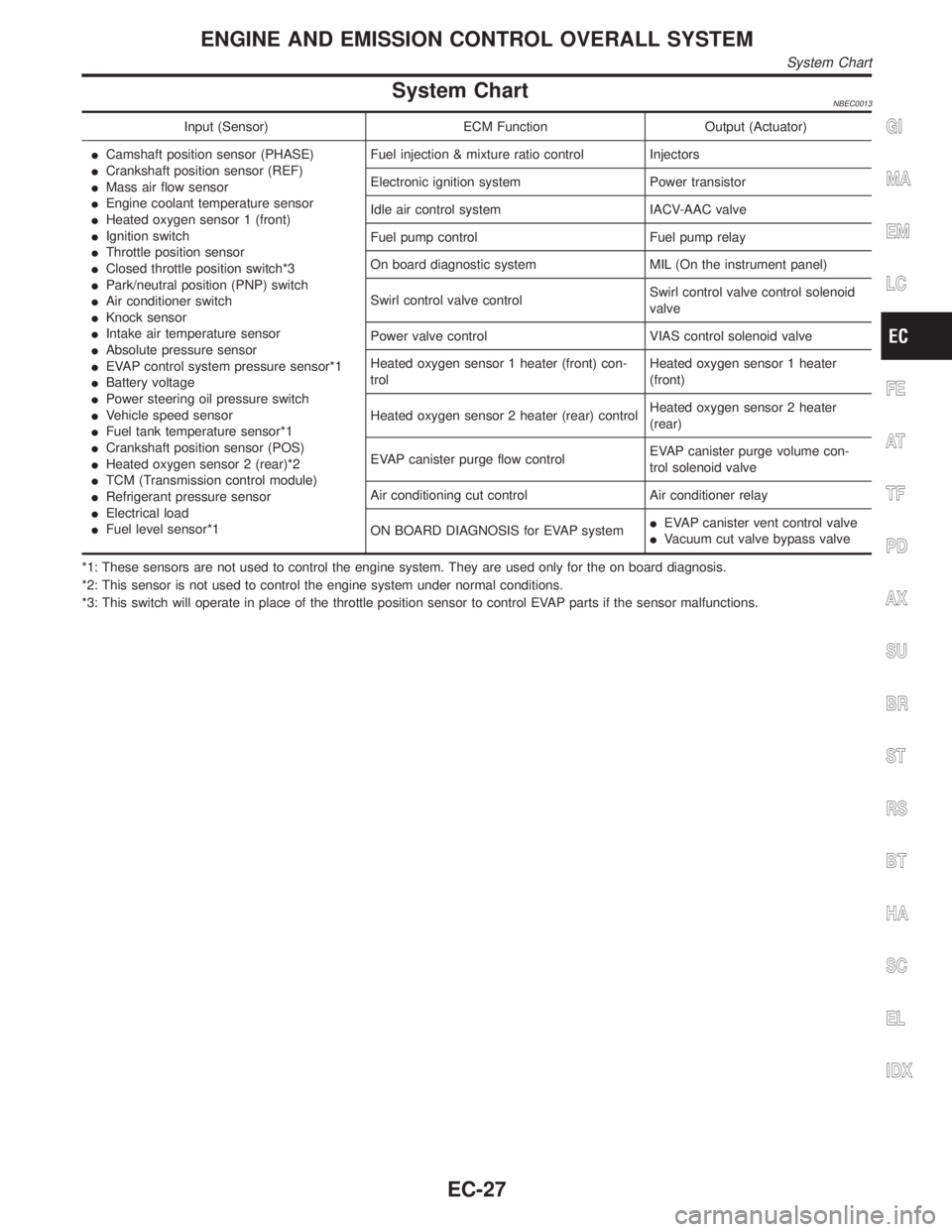
System ChartNBEC0013
Input (Sensor) ECM Function Output (Actuator)
ICamshaft position sensor (PHASE)
ICrankshaft position sensor (REF)
IMass air flow sensor
IEngine coolant temperature sensor
IHeated oxygen sensor 1 (front)
IIgnition switch
IThrottle position sensor
IClosed throttle position switch*3
IPark/neutral position (PNP) switch
IAir conditioner switch
IKnock sensor
IIntake air temperature sensor
IAbsolute pressure sensor
IEVAP control system pressure sensor*1
IBattery voltage
IPower steering oil pressure switch
IVehicle speed sensor
IFuel tank temperature sensor*1
ICrankshaft position sensor (POS)
IHeated oxygen sensor 2 (rear)*2
ITCM (Transmission control module)
IRefrigerant pressure sensor
IElectrical load
IFuel level sensor*1Fuel injection & mixture ratio control Injectors
Electronic ignition system Power transistor
Idle air control system IACV-AAC valve
Fuel pump control Fuel pump relay
On board diagnostic system MIL (On the instrument panel)
Swirl control valve controlSwirl control valve control solenoid
valve
Power valve control VIAS control solenoid valve
Heated oxygen sensor 1 heater (front) con-
trolHeated oxygen sensor 1 heater
(front)
Heated oxygen sensor 2 heater (rear) controlHeated oxygen sensor 2 heater
(rear)
EVAP canister purge flow controlEVAP canister purge volume con-
trol solenoid valve
Air conditioning cut control Air conditioner relay
ON BOARD DIAGNOSIS for EVAP systemIEVAP canister vent control valve
IVacuum cut valve bypass valve
*1: These sensors are not used to control the engine system. They are used only for the on board diagnosis.
*2: This sensor is not used to control the engine system under normal conditions.
*3: This switch will operate in place of the throttle position sensor to control EVAP parts if the sensor malfunctions.GI
MA
EM
LC
FE
AT
TF
PD
AX
SU
BR
ST
RS
BT
HA
SC
EL
IDX
ENGINE AND EMISSION CONTROL OVERALL SYSTEM
System Chart
EC-27
Page 1407 of 2395

System DescriptionNBEL0216Refer to Owner's Manual for ASCD operating instructions.
POWER SUPPLY AND GROUNDNBEL0216S01Power is supplied at all times:
Ithrough 10A fuse [No. 14, located in the fuse block (J/B)]
Ito the stop lamp switch terminal 1, and
Ithrough 7.5A fuse (No. 52, located in fuse and fusible link box)
Ito the horn relay terminals 1 and 3.
When ignition switch is in the ON or START position, power is supplied:
Ithrough 7.5A fuse [No. 11, located in the fuse block (J/B)]
Ito ASCD brake switch terminal 1 and
Ito ASCD control unit terminal 5,
Ithrough 10A fuse [No. 18, located in the fuse block (J/B)]
Ito park/neutral position relay terminal 1,
Ithrough 10A fuse [No. 8, located in the fuse block (J/B)]
Ito combination meter terminal 66, and
When park/neutral position switch is in the P or N position, ground is supplied:
Ito park/neutral position relay terminal 2
Ithrough park/neutral position switch and body grounds B55 and B75.
When ASCD main switch is depressed (ON), ground is supplied:
Ito ASCD control unit terminal 9
Ifrom ASCD steering switch terminal 4
Ito ASCD steering switch terminal 5
Ithrough body grounds M4, M66 and M147
then ASCD control unit holds CRUISE condition and illuminates CRUISE indicator.
Ground is supplied:
Ifrom ASCD control unit terminal 15
Ito combination meter terminal 46.
OPERATIONNBEL0216S02Set OperationNBEL0216S0201To activate the ASCD, all following conditions must exist.
IGround supply to ASCD control unit terminal 9 (Main switch is in ON position.)
IPower supply to ASCD control unit terminal 8 (Brake pedal is released and A/T selector lever is in other
than P and N position.)
IVehicle speed is between 40 km/h (25 MPH) and 144 km/h (89 MPH). (Signal from combination meter)
When the SET/COAST switch is depressed, power is supplied:
Ifrom ASCD steering switch terminal 2
Ito ASCD control unit terminal 11.
And then ASCD pump is activated to control throttle wire and ASCD control unit supply ground
Ito combination meter terminals 51 to illuminate SET indicator.
A/T Overdrive Control during Cruise Control DrivingNBEL0216S0202When the vehicle speed is approximately 3 km/h (2 MPH) below set speed, a signal is sent
Ifrom ASCD control unit terminal 10
Ito TCM (transmission control module) terminal 24.
When this occurs, the TCM (transmission control module) cancels overdrive.
After vehicle speed is approximately 1 km/h (1 MPH) below set speed, overdrive is reactivated.
ASCD Shifting ControlNBEL0216S0203During ASCD cruise, ASCD control unit controls A/T shifting to avoid uncomfortable shifting.
This is used to control the signals below.
IThrottle position sensor from ECM
AUTOMATIC SPEED CONTROL DEVICE (ASCD)
System Description
EL-222
Page 1408 of 2395

IA/T shift solenoid valve A
Coast OperationNBEL0216S0204When the SET/COAST switch is depressed during cruise control driving, ASCD actuator returns the throttle
cable to decrease vehicle set speed until the switch is released. And then ASCD will keep the new set speed.
Accel OperationNBEL0216S0205When the RESUME/ACCEL switch is depressed, power is supplied
Ifrom ASCD steering switch terminal 3
Ito ASCD control unit terminal 24.
If the RESUME/ACCEL switch is depressed during cruise control driving, ASCD actuator pulls the throttle cable
to increase the vehicle speed until the switch is released or vehicle speed is reached to maximum controlled
speed by the system. And then ASCD will keep the new set speed.
Cancel OperationNBEL0216S0206When any of following condition exists, cruise operation will be canceled.
ICANCEL switch is depressed. (Power supply to ASCD control unit terminals 11 and 24)
IBrake pedal is depressed. (Power supply to ASCD control unit terminal 23 from stop lamp switch)
IBrake pedal is depressed or A/T selector lever is shifted to P or N position. (Power supply to ASCD con-
trol unit terminal 8 is interrupted.)
If MAIN switch is turned to OFF during ASCD is activated, all of ASCD operation will be canceled and vehicle
speed memory will be erased.
Resume OperationNBEL0216S0207When the RESUME/ACCEL switch is depressed after cancel operation other than depressing MAIN switch is
performed, vehicle speed will return to last set speed. To resume vehicle set speed, vehicle condition must
meet following conditions.
IBrake pedal is released.
IA/T selector lever is in other than P and N position.
IVehicle speed is between 40 km/h (25 MPH) and 144 km/h (89 MPH).
ASCD PUMP OPERATIONNBEL0216S03The ASCD pump consists of a vacuum motor, an air valve and a release valve. When the ASCD activates,
power is supplied
Ifrom terminal 12 of ASCD control unit
Ito ASCD pump terminal 1.
Ground is supplied to vacuum motor, air valve and release valve from ASCD control unit depending on the
operated condition as shown in the below table.
The pump is connected to ASCD actuator by vacuum hose. When the ASCD pump is activated, the ASCD
pump vacuum the diaphragm of ASCD actuator to control throttle cable.
Air valve (*1) Release valve (*1) Vacuum motorActuator inner pres-
sure
ASCD not operating Open Open Stopped Atmosphere
ASCD operatingReleasing throttle
cableOpen Closed Stopped Vacuum
Holding throttle
positionClosed Closed Stopped Vacuum (*2)
Pulling throttle cable Closed Closed Operated Vacuum
*1: When power and ground is supplied, valve is closed.
*2: Set position held.
GI
MA
EM
LC
EC
FE
AT
TF
PD
AX
SU
BR
ST
RS
BT
HA
SC
IDX
AUTOMATIC SPEED CONTROL DEVICE (ASCD)
System Description (Cont'd)
EL-223
Page 1415 of 2395

Trouble DiagnosesNBEL0218SYMPTOM CHARTNBEL0218S01
PROCEDURE Diagnostic procedure
REFERENCE PAGE (EL- ) 231 232 233 234 235 235 237
SYMPTOM
FAIL-SAFE SYSTEM CHECK
POWER SUPPLY AND GROUND CIRCUIT CHECK
ASCD BRAKE/STOP LAMP SWITCH CHECK
ASCD STEERING SWITCH CHECK
VEHICLE SPEED SENSOR CHECK
ASCD PUMP CIRCUIT CHECK
ASCD ACTUATOR/PUMP CHECK
ASCD cannot be set. (ªCRUISEº indica-
tor lamp does not ON.)XXH3
ASCD cannot be set. (ªSETº indicator
lamp does not blink.)XXX
ASCD cannot be set. (ªSETº indicator
lamp blinks.H1)X XXXX
Vehicle speed does not decrease after
SET/COAST switch has been pressed.XX
Vehicle speed does not return to the set
speed after RESUME/ACCEL switch has
been pressed.H2XX
Vehicle speed does not increase after
RESUME/ACCEL switch has been
pressed.XX
System is not released after CANCEL
switch (steering) has been pressed.XX
Large difference between set speed and
actual vehicle speed.XXX
Deceleration is greatest immediately
after ASCD has been set.XXX
H1: It indicates that system is in fail-safe. After completing diagnostic procedures, perform ªFAIL-SAFE SYSTEM CHECKº (EL-231) to
verify repairs.
H2: If vehicle speed is greater than 40 km/h (25 MPH) after system has been released, pressing RESUME/ACCEL switch returns vehicle
speed to the set speed previously achieved. However, doing so when the ASCD main switch is turned to ªOFFº, vehicle speed will not
return to the set speed since the memory is canceled.
H3: Check only main switch built-in steering switch.
AUTOMATIC SPEED CONTROL DEVICE (ASCD)
Trouble Diagnoses
EL-230
Page 1659 of 2395
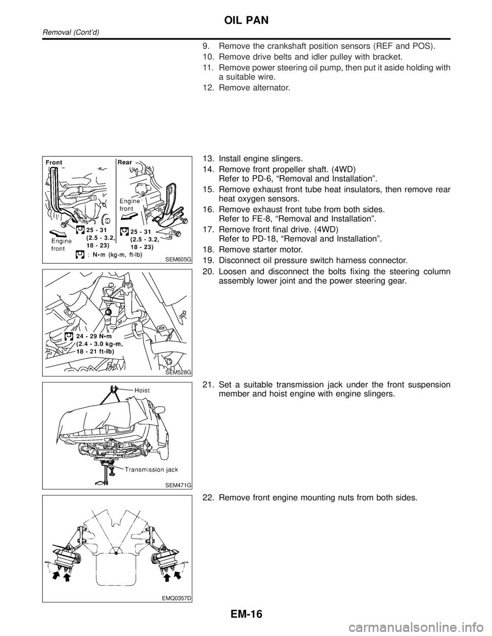
9. Remove the crankshaft position sensors (REF and POS).
10. Remove drive belts and idler pulley with bracket.
11. Remove power steering oil pump, then put it aside holding with
a suitable wire.
12. Remove alternator.
SEM605G
13. Install engine slingers.
14. Remove front propeller shaft. (4WD)
Refer to PD-6, ªRemoval and Installationº.
15. Remove exhaust front tube heat insulators, then remove rear
heat oxygen sensors.
16. Remove exhaust front tube from both sides.
Refer to FE-8, ªRemoval and Installationº.
17. Remove front final drive. (4WD)
Refer to PD-18, ªRemoval and Installationº.
18. Remove starter motor.
19. Disconnect oil pressure switch harness connector.
SEM528G
20. Loosen and disconnect the bolts fixing the steering column
assembly lower joint and the power steering gear.
SEM471G
21. Set a suitable transmission jack under the front suspension
member and hoist engine with engine slingers.
EMQ0357D
22. Remove front engine mounting nuts from both sides.
OIL PAN
Removal (Cont'd)
EM-16
Page 1666 of 2395
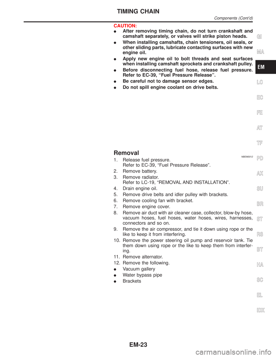
CAUTION:
IAfter removing timing chain, do not turn crankshaft and
camshaft separately, or valves will strike piston heads.
IWhen installing camshafts, chain tensioners, oil seals, or
other sliding parts, lubricate contacting surfaces with new
engine oil.
IApply new engine oil to bolt threads and seat surfaces
when installing camshaft sprockets and crankshaft pulley.
IBefore disconnecting fuel hose, release fuel pressure.
Refer to EC-39, ªFuel Pressure Releaseº.
IBe careful not to damage sensor edges.
IDo not spill engine coolant on drive belts.
RemovalNBEM00121. Release fuel pressure.
Refer to EC-39, ªFuel Pressure Releaseº.
2. Remove battery.
3. Remove radiator.
Refer to LC-19, ªREMOVAL AND INSTALLATIONº.
4. Drain engine oil.
5. Remove drive belts and idler pulley with brackets.
6. Remove cooling fan with bracket.
7. Remove engine cover.
8. Remove air duct with air cleaner case, collector, blow-by hose,
vacuum hoses, fuel hoses, water hoses, wires, harnesses,
connectors and so on.
9. Remove the air compressor, and tie it down using rope or the
like to keep it from interfering.
10. Remove the power steering oil pump and reservoir tank. Tie
them down using rope or the like to keep them from interfer-
ing.
11. Remove alternator.
12. Remove the following.
IVacuum gallery
IWater bypass pipe
IBrackets
GI
MA
LC
EC
FE
AT
TF
PD
AX
SU
BR
ST
RS
BT
HA
SC
EL
IDX
TIMING CHAIN
Components (Cont'd)
EM-23
Page 1702 of 2395
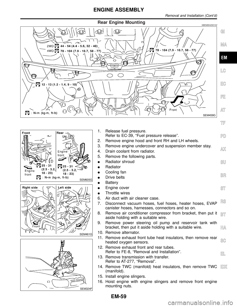
Rear Engine MountingNBEM0042S0102
SEM459G
SEM605G
SEM461G
SEM324F
1. Release fuel pressure.
Refer to EC-39, ªFuel pressure releaseº.
2. Remove engine hood and front RH and LH wheels.
3. Remove engine undercover and suspension member stay.
4. Drain coolant from radiator.
5. Remove the following parts.
IRadiator shroud
IRadiator
ICooling fan
IDrive belts
IBattery
IEngine cover
IThrottle wires
6. Air duct with air cleaner case.
7. Disconnect vacuum hoses, fuel hoses, heater hoses, EVAP
canister hoses, harnesses, connectors and so on.
8. Remove air conditioner compressor from bracket, then put it
aside holding with a suitable wire.
9. Remove power steering oil pump and reservoir tank with
bracket, then put it aside holding with a suitable wire.
10. Remove alternator.
11. Remove exhaust front tube heat insulators, then remove rear
heated oxygen sensors.
12. Remove exhaust front and rear tubes.
Refer to FE-8, ªRemoval and Installationº.
13. Remove transmission with transfer.
Refer to AT-277, ªRemovalº.
14. Remove TWC (manifold) heat insulators, then remove TWC
(manifold).
15. Install engine slingers.
16. Hoist engine with engine slingers and remove front engine
mounting nuts.
GI
MA
LC
EC
FE
AT
TF
PD
AX
SU
BR
ST
RS
BT
HA
SC
EL
IDX
ENGINE ASSEMBLY
Removal and Installation (Cont'd)
EM-59
Page 1745 of 2395
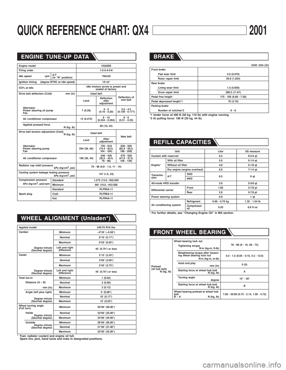
QUICK REFERENCE CHART: QX42001
Engine model VQ35DE
Firing order 1-2-3-4-5-6
Idle speed rpmA/T
(in ªNº position)750 50
Ignition timing (degree BTDC at idle speed) 15É 2É
CO% at idleIdle mixture screw is preset and
sealed at factory.
Drive belt deflection (Cold) mm (in) Used belt
Deflection of
new belt
LimitDeflection
after
adjustment
Alternator
Power steering oil pump
Fan7 (0.28)4-5
(0.16 - 0.20)3.5 - 4.5
(0.138 - 0.177)
Air conditioner compressor 12 (0.472)9-10
(0.354 - 0.394)8-9
(0.31 - 0.35)
Applied pressed force
N (kg, lb)98 (10, 22)
Drive belt tension adjustment (Cold)
N (kg, lb)Used belt
New belt
LimitAfter
adjustment
Alternator
Power steering pump
Fan294 (30, 66)730 - 818
(74.4 - 83.5,
164 - 184)838 - 926
(85.4 - 94.5,
188 - 208)
Air conditioner compressor 196 (20, 44)348 - 436
(35.5 - 44.5,
78 - 98)470 - 559
(47.9 - 57.0,
106 - 126)
Radiator cap relief pressure
kPa (kg/cm
2, psi)78 - 98 (0.8 - 1.0, 11 - 14)
Cooling system leakage testing pressure
kPa (kg/cm
2, psi)157 (1.6, 23)
Compression pressure
kPa (kg/cm
2, psi)/rpmStandard 1,275 (13.0, 185)/300
Minimum 981 (10.0, 142)/300
Spark plugStandard PLFR5A-11
Cold PLFR6A-11
Hot PLFR4A-11
Applied model 245/70 R16 tire
Camber
Degree minute
(Decimal degree)Minimum þ0É35¢(þ0.58É)
Nominal 0É10¢(0.17É)
Maximum 0É55¢(0.92É)
Left and right
difference45¢(0.75É) or less
Caster
Degree minute
(Decimal degree)Minimum 2É15¢(2.25É)
Nominal 3É00¢(3.00É)
Maximum 3É45¢(3.75É)
Left and right
difference45¢(0.75É) or less
Total toe-in Minimum 1 (0.04)
Distance (A þ B)
mm (in)Nominal 2 (0.08)
Maximum 3 (0.12)
Angle (left plus right)
Degree minute
(Decimal degree)Minimum 5¢(0.08É)
Nominal 10¢(0.17É)
Maximum 15¢(0.25É)
Wheel turning angle
(Full turn)Minimum 30É00¢(30.00É)
Inside
Degree minute
(Decimal degree)Nominal 33É00¢(33.00É)
Maximum 34É00¢(34.00É)
Outside
Degree minute
(Decimal degree)Minimum 28É00¢(28.00É)
Nominal 31É00¢(31.00É)
Maximum 32É00¢(32.00É)
* Fuel, radiator coolant and engine oil full.
Spare tire, jack, hand tools and mats in designated positions.
Unit: mm (in)Front brake
Pad wear limit 2.0 (0.079)
Rotor repair limit 26.0 (1.024)
Rear brake
Lining wear limit 1.5 (0.059)
Drum repair limit 296.5 (11.67)
Pedal free height 175 - 185 (6.89 - 7.28)
Pedal depressed height*1 70 (2.76)
Parking brake
Number of notches*2 6 - 8
*1 Under force of 490 N (50 kg, 110 lb) with engine running
*2 At pulling force: 196 N (20 kg, 44 lb)
Unit Liter US measure
Coolant with reservoir 9.2 9-3/4 qt
Engine*With oil filter 5.0 5-1/4 qt
Without oil filter 4.8 5-1/8 qt
Dry engine (engine overhaul) 6.8 7-1/4 qt
Transmis-
sionA/T2WD
8.5 9 qt
4WD
All-mode 4WD transfer 3.0 2-5/8 qt
Differential carrierFront 1.85 3-7/8 pt
Rear 2.8 5-7/8 pt
Power steering system 0.9 1 qt
Air conditioning systemRefrigerant 0.60 - 0.70 kg 1.32 - 1.54 lb
Compressor
oil0.20 6.8 fl oz
* For further details, see ªChanging Engine Oilº in MA section.
Preload
(At hub bolt)
N (kg, lb)Wheel bearing lock nut
78-98(8-10,58-72)
Tightening torque
N×m (kg-m, ft-lb)
Retightening torque after loosen-
ing wheel bearing lock nut
N×m (kg-m, in-lb)0.5 - 1.5 (0.05 - 0.15, 4.3 - 13.0)
Axial end play
mm (in)0 (0)
Starting force at wheel hub bolt
N (kg, lb)A
Turning angle
degree15É - 30É
Starting force at wheel hub bolt
N (kg, lb)B
Wheel bearing preload at wheel hub
bolt
B þ A N (kg, lb)7.06 - 20.99 (0.72 - 2.14, 1.59 - 4.72)
Page 1965 of 2395

LSV (Load sensing valve) ..............................BR-12
Lubricant (R134a) A/C..................................HA-146
Lubricants .......................................................MA-11
Lubrication circuit (engine) ...............................LC-3
Lubrication-locks, hinges and hood
latches ........................................................MA-27
Luggage room lamp ........................................EL-88
M
MAFS - Wiring diagram................................EC-154
Magnet clutch .......................................HA-104, 150
MAIN - Wiring diagram.................................EC-142
Main oil pump (Transfer)...............................TF-131
Mainshaft (Transfer) ......................................TF-125
Maintenance (engine) ....................................MA-13
MAJOR OVERHALL......................................AT-281
Major overhaul (Transfer) .............................TF-120
Malfunction indicator lamp (MIL) ....................EC-74
Mass air flow sensor (MAFS) .......................EC-150
Master cylinder (brake) ..................................BR-16
Meter ...............................................................EL-94
METER - Wiring diagram................................EL-99
MIL & Data link connectors circuit ...............EC-648
MIL/DL - Wiring diagram ..............................EC-648
MIRROR - Wiring diagram............................EL-177
Mirror defogger .............................................EL-151
Mirror, door......................................................BT-56
Mirror, out side ................................................BT-56
Misfire ...........................................................EC-320
Mode door control linkage adjustment ...........HA-81
Mode door motor ............................................HA-75
Model variation ................................................GI-41
Molding - See Exterior ....................................BT-35
MULTI - Wiring diagram ................................EL-274
Multi-remote control system..........................EL-270
Multiplex communication ..............................HA-142
Multiport fuel injection (MFI) system ..............EC-28
Multiport fuel injection precautions ....................GI-6
N
NATS (Nissan anti-theft system)...................EL-328
NATS (Nissan anti-theft system)
precautions ....................................................GI-3
NATS - Wiring diagram .................................EL-330
NAVI - wiring diagram ...................................EL-394
Navigation System ........................................EL-385
Neutral-4LO switch ........................................TF-112
NVH troubleshooting (AX) ..........................AX-3, 18
NVH troubleshooting (BR)................................BR-6
NVH troubleshooting (PD)................................PD-3
NVH troubleshooting (ST).................................ST-6
NVH troubleshooting (SU) .........................SU-3, 15O
Oil change (capacity) .....................................MA-11
Oil filter (Transfer) .........................................TF-118
Oil pan (engine) .............................................EM-15
Oil pressure (engine) ........................................LC-4
Oil pump (A/T) ...............................................AT-297
Oil pump (engine) .............................................LC-5
Oil pump regulator valve (engine) ....................LC-6
Oil seal replacement (engine)........................EM-35
Oil seal replacement (front final drive
4WD) ...........................................................PD-15
Oil seal replacement (front of final
drive) ...........................................................PD-40
On board diagnostic system ..........................EC-59
Out side mirror ................................................BT-56
Overdrive control switch ................................AT-263
Overrun clutch ...............................................AT-320
Overrun clutch solenoid valve .......................AT-189
P
P/ANT - Wiring diagram ................................EL-170
Park/Neutral position switch .........................EC-604
Park/neutral position switch (A/T) .........AT-103, 263
Parking brake control .....................................BR-30
Parking lamp ...................................................EL-61
PCV (positive crankcase ventilation) .............EC-38
PGC/V - Wiring diagram ......................EC-370, 544
PHASE - Wiring diagram .............................EC-342
Pinion bearing preload diff. ............................PD-25
Pinion gear height diff. .............................PD-25, 53
Piston assembly .............................................EM-71
Piston pin inspection ......................................EM-63
Piston ring inspection.....................................EM-64
Piston to bore clearance ................................EM-66
Planetary carrier (Transfer) ...........................TF-134
PNP/SW - Wiring diagram ...........................EC-607
POS - Wiring diagram ..................................EC-517
POWER - Wiring diagram...............................EL-10
Power antenna ..............................................EL-169
Power door lock ............................................EL-254
Power door mirror .........................................EL-177
Power seat ....................................................EL-181
Power steering fluid level .....................MA-27, ST-8
Power steering gear........................................ST-17
Power steering hydraulic pressure .................ST-10
Power steering oil pressure switch ..............EC-634
Power steering oil pump .................................ST-27
Power steering system bleeding.......................ST-9
Power supply routing ........................................EL-9
Power transistor & ignition coil.....................EC-499
Power window ...............................................EL-241
PRE/SE - Wiring diagram ............................EC-384
Precations for Leak detection dye ...................HA-3
Precautions (General) .......................................GI-5
Pressure test (A/T) ..........................................AT-62
Propeller shaft ..................................................PD-3
ALPHABETICAL INDEX
IDX-6