engine oil INFINITI QX4 2001 Factory Service Manual
[x] Cancel search | Manufacturer: INFINITI, Model Year: 2001, Model line: QX4, Model: INFINITI QX4 2001Pages: 2395, PDF Size: 43.2 MB
Page 2014 of 2395

SMA010
2. Clean oil filter mounting surface on cylinder block. Coat rubber
seal of new oil filter with engine oil.
SMA702C
3. Screw in the oil filter until a slight resistance is felt, then tighten
an additional 2/3 turn.
4. Add engine oil.
Refer to MA-18, ªChanging Engine Oilº.
IClean excess oil from engine.
SMA098D
Changing Spark PlugsNBMA00171. Remove engine cover.
2. Remove throttle wires.
3. Remove air duct with air cleaner assembly.
4. Disconnect harness connectors and harness brackets around
ignition coil sides.
5. Remove throttle body. (Only when removing the No. 4 cylinder
spark plug)
6. Disconnect ignition coil harness connectors.
7. Loosen ignition coil fixing bolts and pull out coil from intake
manifold connector.
Ignition coil:
: 8.5 - 10.7 N´m (0.86 - 1.1 kg-m, 75 - 95 in-lb)
SEM294A
8. Check type and gap of new spark plug.
Spark plug type:
Symbol Make
Standard type PLFR5A-11 NGK
Cold type PLFR6A-11 NGK
Hot type PLFR4A-11 NGK
Gap (Nominal): 1.1 mm (0.043 in)
Spark plug:
GI
EM
LC
EC
FE
AT
TF
PD
AX
SU
BR
ST
RS
BT
HA
SC
EL
IDX
ENGINE MAINTENANCE
Changing Oil Filter (Cont'd)
MA-19
Page 2017 of 2395

2WD, 4WD model
8.5(9 US qt, 7-1/2 Imp qt)
Drain plug:
: 29 - 39 N´m (3.0 - 4.0 kg-m, 22 - 29 ft-lb)
4. Run engine at idle speed for five minutes.
5. Check fluid level and condition. Refer to MA-21, ªChecking A/T
Fluidº. If fluid is still dirty, repeat steps 2 through 5.
SMA439B
Checking All-mode 4WD Transfer FluidNBMA0022Check for oil leakage and fluid level.
A/T fluid is used for the all-mode 4WD transfer in the factory.
Never start engine while checking fluid level.
Filler plug:
: 10 - 20 N´m (1.0 - 2.0 kg-m, 87 - 174 in-lb)
SMA444B
Changing All-mode 4WD Transfer FluidNBMA0023When changing all-mode 4WD transfer fluid completely, A/T fluid
may be used.
Fluid grade:
Nissan Matic ªDº (Continental U.S. and Alaska) or
Canada NISSAN Automatic Transmission Fluid.
Refer to ªFluids and Lubricantsº, ªRECOMMENDED
FLUIDS AND LUBRICANTSº, MA-11.
Fluid capacity:
3.0(3-1/8 US qt, 2-5/8 Imp qt)
Drain plug:
: 10 - 20 N´m (1.0 - 2.0 kg-m, 87 - 174 in-lb)
CHASSIS AND BODY MAINTENANCE
Changing A/T Fluid (Cont'd)
MA-22
Page 2024 of 2395
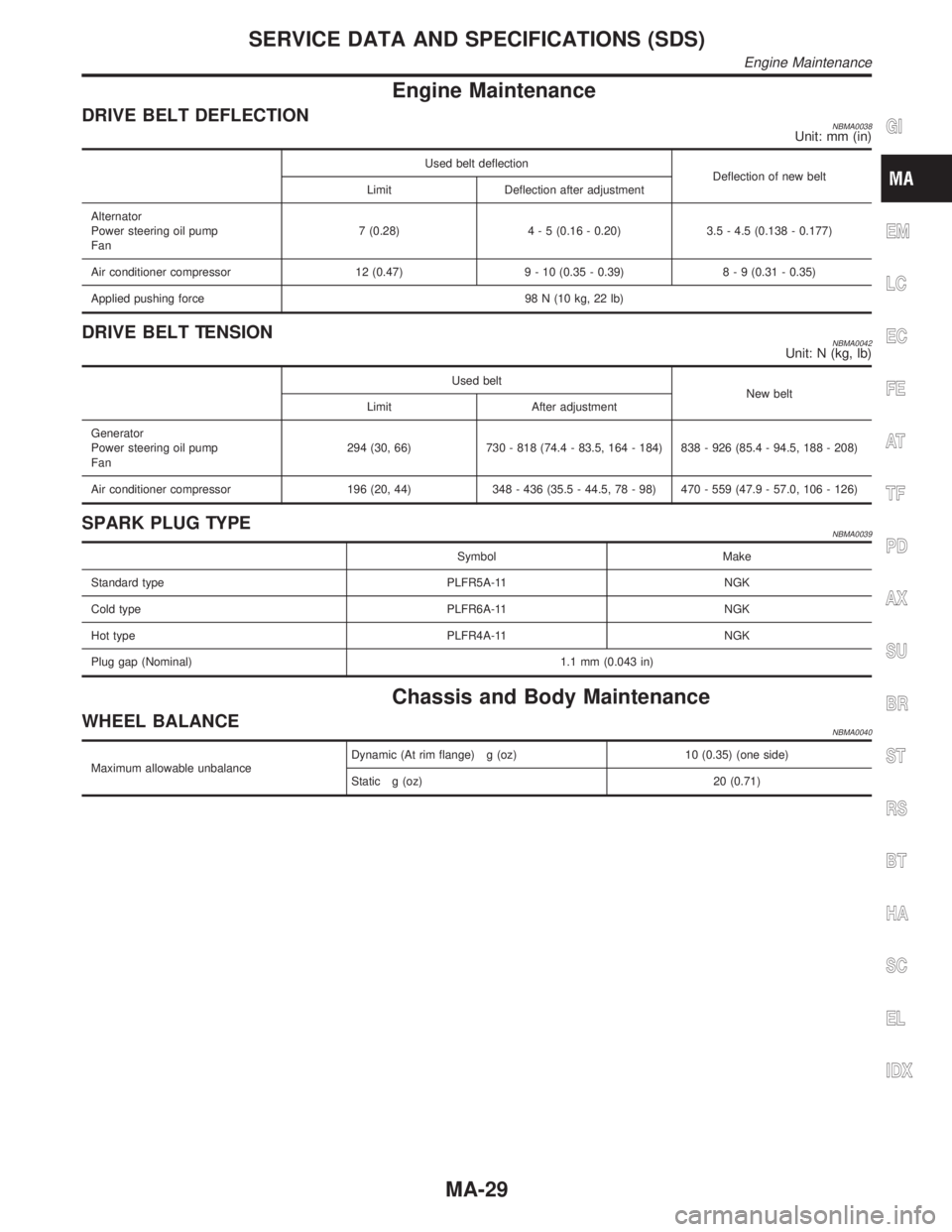
Engine Maintenance
DRIVE BELT DEFLECTIONNBMA0038Unit: mm (in)
Used belt deflection
Deflection of new belt
Limit Deflection after adjustment
Alternator
Power steering oil pump
Fan7 (0.28)4 - 5 (0.16 - 0.20) 3.5 - 4.5 (0.138 - 0.177)
Air conditioner compressor 12 (0.47) 9 - 10 (0.35 - 0.39)8 - 9 (0.31 - 0.35)
Applied pushing force 98 N (10 kg, 22 lb)
DRIVE BELT TENSIONNBMA0042Unit: N (kg, lb)
Used belt
New belt
Limit After adjustment
Generator
Power steering oil pump
Fan294 (30, 66) 730 - 818 (74.4 - 83.5, 164 - 184) 838 - 926 (85.4 - 94.5, 188 - 208)
Air conditioner compressor 196 (20, 44) 348 - 436 (35.5 - 44.5, 78 - 98) 470 - 559 (47.9 - 57.0, 106 - 126)
SPARK PLUG TYPENBMA0039
Symbol Make
Standard type PLFR5A-11 NGK
Cold type PLFR6A-11 NGK
Hot type PLFR4A-11 NGK
Plug gap (Nominal) 1.1 mm (0.043 in)
Chassis and Body Maintenance
WHEEL BALANCENBMA0040
Maximum allowable unbalanceDynamic (At rim flange) g (oz) 10 (0.35) (one side)
Static g (oz) 20 (0.71)
GI
EM
LC
EC
FE
AT
TF
PD
AX
SU
BR
ST
RS
BT
HA
SC
EL
IDX
SERVICE DATA AND SPECIFICATIONS (SDS)
Engine Maintenance
MA-29
Page 2189 of 2395

SST601C
Checking Gear Housing MovementNBST00081. Check the movement of steering gear housing during station-
ary steering on a dry paved surface.
IApply a force of 49 N (5 kg, 11 lb) to steering wheel to check
the gear housing movement.
Turn off ignition key while checking.
Movement of gear housing:
±2mm(±0.08 in) or less
2. If movement exceeds the limit, replace mount insulator after
confirming proper installation of gear housing clamps.
SST602C
Adjusting Rack RetainerNBST0009IPerform this driving test on a flat road.
a) Check whether vehicle moves in a straight line when steering
wheel is released.
b) Check whether steering wheel returns to neutral position when
steering wheel is released from a slightly turned (approx. 20É)
position.
IIf any abnormality is found, correct it by resetting adjusting
screw.
Checking and Adjusting Drive BeltsNBST0010Refer to MA-13, ªChecking Drive Beltsº.
SST280BA
Checking Fluid LevelNBST0011Check fluid level.
Use the correct range of the dipstick depending on the fluid tem-
perature. Use the ªHOTº range at 50 to 80ÉC (122 to 176ÉF), or the
ªCOLDº range at 0 to 30ÉC (32 to 86ÉF).
CAUTION:
IDo not overfill.
IRecommended fluid is Genuine Nissan PSF II or equiva-
lent. Refer to MA-11, ªFluids and Lubricantsº.
SST458C
Checking Fluid LeakageNBST0012Check the lines for improper attachment and for leaks, cracks,
damage, loose connections, chafing and deterioration.
1. Run engine between idle speed and 1,000 rpm.
Make sure temperature of fluid in oil tank rises to 60 to 80ÉC
(140 to 176ÉF).
2. Turn steering wheel right-to-left several times.
3. Hold steering wheel at each ªlockº position for five seconds
and carefully check for fluid leakage.
ON-VEHICLE SERVICE
Checking Gear Housing Movement
ST-8
Page 2190 of 2395
CAUTION:
Do not hold the steering wheel in a locked position for more
than 15 seconds.
4. If fluid leakage at connectors is noticed, loosen flare nut and
then retighten.
Do not overtighten connector as this can damage O-ring,
washer and connector.
5. Check rack boots for accumulation of power steering fluid.
Bleeding Hydraulic SystemNBST00131. Raise front end of vehicle until wheels are clear of the ground.
2. Add fluid into oil tank to specified level. Then, quickly turn
steering wheel fully to right and left and lightly touch steering
stoppers.
Repeat steering wheel operation until fluid level no longer
decreases.
3. Start engine.
Repeat step 2 above.
IIncomplete air bleeding will cause the following to occur. When
this happens, bleed air again.
a) Air bubbles in reservoir tank
b) Clicking noise in oil pump
c) Excessive buzzing in oil pump
Fluid noise may occur in the valve or oil pump. This is common
when the vehicle is stationary or while turning steering wheel
slowly. This does not affect performance or durability of the system.
SST491B
SST090B
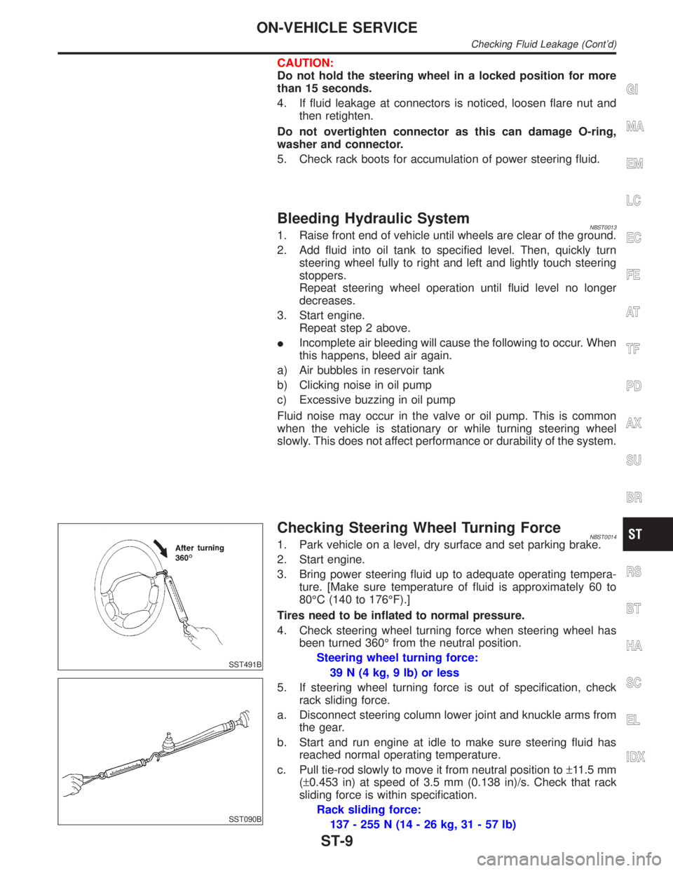
Checking Steering Wheel Turning ForceNBST00141. Park vehicle on a level, dry surface and set parking brake.
2. Start engine.
3. Bring power steering fluid up to adequate operating tempera-
ture. [Make sure temperature of fluid is approximately 60 to
80ÉC (140 to 176ÉF).]
Tires need to be inflated to normal pressure.
4. Check steering wheel turning force when steering wheel has
been turned 360É from the neutral position.
Steering wheel turning force:
39 N (4 kg, 9 lb) or less
5. If steering wheel turning force is out of specification, check
rack sliding force.
a. Disconnect steering column lower joint and knuckle arms from
the gear.
b. Start and run engine at idle to make sure steering fluid has
reached normal operating temperature.
c. Pull tie-rod slowly to move it from neutral position to±11.5 mm
(±0.453 in) at speed of 3.5 mm (0.138 in)/s. Check that rack
sliding force is within specification.
Rack sliding force:
137 - 255 N (14 - 26 kg, 31 - 57 lb)
GI
MA
EM
LC
EC
FE
AT
TF
PD
AX
SU
BR
RS
BT
HA
SC
EL
IDX
ON-VEHICLE SERVICE
Checking Fluid Leakage (Cont'd)
ST-9
Page 2217 of 2395
SBR686C
Precautions
PRECAUTIONSNBSU0001IWhen installing rubber parts, final tightening must be car-
ried out under unladen condition* with tires on ground.
*Fuel, radiator coolant and engine oil full. Spare tire, jack,
hand tools and mats in designated positions.
IUse flare nut wrench when removing and installing brake
tubes.
IAfter installing removed suspension parts, check wheel
alignment and adjust if necessary.
IAlways torque brake lines when installing.
Preparation
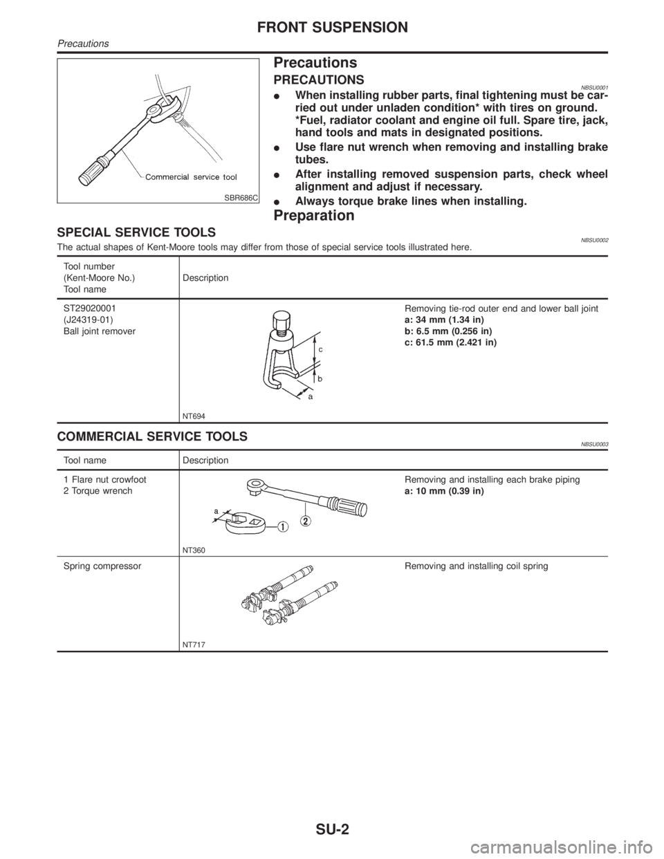
SPECIAL SERVICE TOOLSNBSU0002The actual shapes of Kent-Moore tools may differ from those of special service tools illustrated here.
Tool number
(Kent-Moore No.)
Tool nameDescription
ST29020001
(J24319-01)
Ball joint remover
NT694
Removing tie-rod outer end and lower ball joint
a: 34 mm (1.34 in)
b: 6.5 mm (0.256 in)
c: 61.5 mm (2.421 in)
COMMERCIAL SERVICE TOOLSNBSU0003
Tool name Description
1 Flare nut crowfoot
2 Torque wrench
NT360
Removing and installing each brake piping
a: 10 mm (0.39 in)
Spring compressor
NT717
Removing and installing coil spring
FRONT SUSPENSION
Precautions
SU-2
Page 2220 of 2395
SMA525A
On-vehicle Service
FRONT SUSPENSION PARTSNBSU0005Check front axle and front suspension parts for excessive play,
cracks, wear and other damage.
1. Shake each front wheel to check for excessive play.
2. Retighten all axle and suspensions nuts and bolts to the speci-
fied torque.
Tightening torque:
Refer to ªComponentsº, SU-8.
SFA392B
3. Check strut (shock absorber) for oil leakage and other dam-
age.
4. Check suspension ball joint for grease leakage and ball joint
dust cover for cracks and other damage.
If ball joint dust cover is cracked or damaged, replace ball joint
assembly.
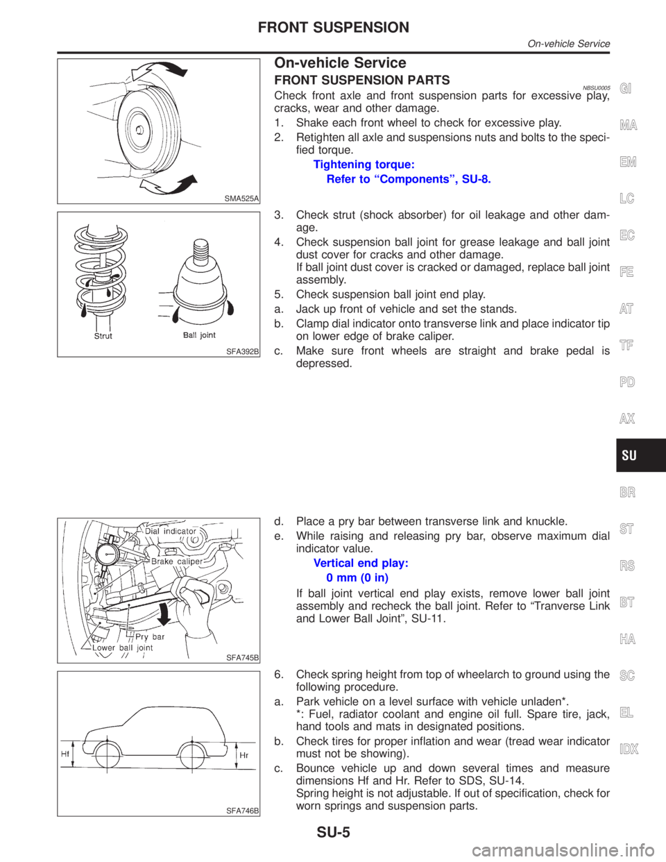
5. Check suspension ball joint end play.
a. Jack up front of vehicle and set the stands.
b. Clamp dial indicator onto transverse link and place indicator tip
on lower edge of brake caliper.
c. Make sure front wheels are straight and brake pedal is
depressed.
SFA745B
d. Place a pry bar between transverse link and knuckle.
e. While raising and releasing pry bar, observe maximum dial
indicator value.
Vertical end play:
0mm(0in)
If ball joint vertical end play exists, remove lower ball joint
assembly and recheck the ball joint. Refer to ªTranverse Link
and Lower Ball Jointº, SU-11.
SFA746B
6. Check spring height from top of wheelarch to ground using the
following procedure.
a. Park vehicle on a level surface with vehicle unladen*.
*: Fuel, radiator coolant and engine oil full. Spare tire, jack,
hand tools and mats in designated positions.
b. Check tires for proper inflation and wear (tread wear indicator
must not be showing).
c. Bounce vehicle up and down several times and measure
dimensions Hf and Hr. Refer to SDS, SU-14.
Spring height is not adjustable. If out of specification, check for
worn springs and suspension parts.
GI
MA
EM
LC
EC
FE
AT
TF
PD
AX
BR
ST
RS
BT
HA
SC
EL
IDX
FRONT SUSPENSION
On-vehicle Service
SU-5
Page 2221 of 2395
SFA975B
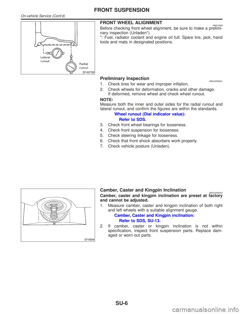
FRONT WHEEL ALIGNMENTNBSU0006Before checking front wheel alignment, be sure to make a prelimi-
nary inspection (Unladen*).
*: Fuel, radiator coolant and engine oil full. Spare tire, jack, hand
tools and mats in designated positions.
Preliminary InspectionNBSU0006S011. Check tires for wear and improper inflation.
2. Check wheels for deformation, cracks and other damage.
If deformed, remove wheel and check wheel runout.
NOTE:
Measure both the inner and outer sides for the radial runout and
lateral runout, and confirm the figures are within the standards.
Wheel runout (Dial indicator value):
Refer to SDS.
3. Check front wheel bearings for looseness.
4. Check front suspension for looseness.
5. Check steering linkage for looseness.
6. Check that front shock absorbers work properly.
7. Check vehicle posture (Unladen).
SFA894
Camber, Caster and Kingpin InclinationNBSU0006S02Camber, caster and kingpin inclination are preset at factory
and cannot be adjusted.
1. Measure camber, caster and kingpin inclination of both right
and left wheels with a suitable alignment gauge.
Camber, Caster and Kingpin inclination:
Refer to SDS, SU-13.
2. If camber, caster or kingpin inclination is not within
specification, inspect front suspension parts. Replace dam-
aged or worn out parts.
FRONT SUSPENSION
On-vehicle Service (Cont'd)
SU-6
Page 2228 of 2395
Service Data and Specifications (SDS)
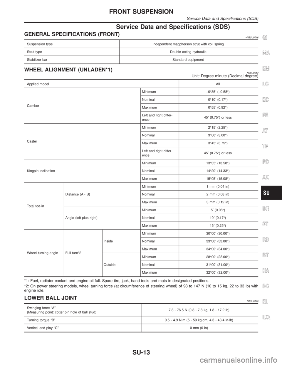
GENERAL SPECIFICATIONS (FRONT)=NBSU0016
Suspension type Independent macpherson strut with coil spring
Strut typeDouble-acting hydraulic
Stabilizer barStandard equipment
WHEEL ALIGNMENT (UNLADEN*1)NBSU0017Unit: Degree minute (Decimal degree)
Applied modelAll
CamberMinimum þ0É35¢(þ0.58É)
Nominal 0É10¢(0.17É)
Maximum 0É55¢(0.92É)
Left and right differ-
ence45¢(0.75É) or less
CasterMinimum 2É15¢(2.25É)
Nominal 3É00¢(3.00É)
Maximum 3É45¢(3.75É)
Left and right differ-
ence45¢(0.75É) or less
Kingpin inclinationMinimum 13É35¢(13.58É)
Nominal 14É20¢(14.33É)
Maximum 15É05¢(15.08É)
Total toe-inDistance (A - B)Minimum 1 mm (0.04 in)
Nominal 2 mm (0.08 in)
Maximum 3 mm (0.12 in)
Angle (left plus right)Minimum 5¢(0.08É)
Nominal 10¢(0.17É)
Maximum 15¢(0.25É)
Wheel turning angle Full turn*2InsideMinimum 30É00¢(30.00É)
Nominal 33É00¢(33.00É)
Maximum 34É00¢(34.00É)
OutsideMinimum 28É00¢(28.00É)
Nominal 31É00¢(31.00É)
Maximum 32É00¢(32.00É)
*1: Fuel, radiator coolant and engine oil full. Spare tire, jack, hand tools and mats in designated positions.
*2: On power steering models, wheel turning force (at circumference of steering wheel) of 98 to 147 N (10 to 15 kg, 22 to 33 lb) with
engine idle.
LOWER BALL JOINTNBSU0018
Swinging force ªAº
(Measuring point: cotter pin hole of ball stud)7.8 - 76.5 N (0.8 - 7.8 kg, 1.8 - 17.2 lb)
Turning torque ªBº 0.5 - 4.9 N´m (5 - 50 kg-cm, 4.3 - 43.4 in-lb)
Vertical end play ªCº0mm(0in)
GI
MA
EM
LC
EC
FE
AT
TF
PD
AX
BR
ST
RS
BT
HA
SC
EL
IDX
FRONT SUSPENSION
Service Data and Specifications (SDS)
SU-13
Page 2229 of 2395

WHEELARCH HEIGHT (UNLADEN*)NBSU0019Unit: mm (in)
SFA746B
Applied model 245/70 R16 tire 245/65 R17 tire
Front (Hf)794 (31.26)
Rear (Hr)810 (31.89)
*: Fuel, radiator coolant and engine oil full. Spare tire, jack, hand tools and mats in designated positions.
WHEEL RUNOUT AVERAGE*NBSU0020Unit: mm (in)
Radial runout limit0.3 (0.012)
Lateral runout limit0.3 (0.012)
*: Wheel runout average = (Outside runout value + Inside runout value) x 0.5
FRONT SUSPENSION
Service Data and Specifications (SDS) (Cont'd)
SU-14