brakes INFINITI QX4 2001 Factory Service Manual
[x] Cancel search | Manufacturer: INFINITI, Model Year: 2001, Model line: QX4, Model: INFINITI QX4 2001Pages: 2395, PDF Size: 43.2 MB
Page 8 of 2395
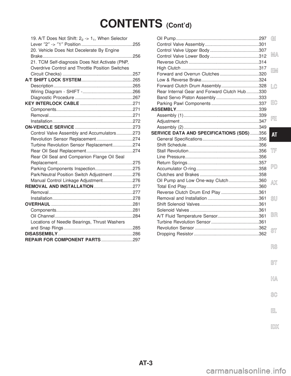
19. A/T Does Not Shift: 22-> 11, When Selector
Lever²2²->²1²Position .........................................255
20. Vehicle Does Not Decelerate By Engine
Brake........................................................................256
21. TCM Self-diagnosis Does Not Activate (PNP,
Overdrive Control and Throttle Position Switches
Circuit Checks) ........................................................257
A/T SHIFT LOCK SYSTEM.........................................265
Description ...............................................................265
Wiring Diagram - SHIFT -........................................266
Diagnostic Procedure ..............................................267
KEY INTERLOCK CABLE..........................................271
Components.............................................................271
Removal ...................................................................271
Installation ................................................................272
ON-VEHICLE SERVICE..............................................273
Control Valve Assembly and Accumulators .............273
Revolution Sensor Replacement .............................274
Turbine Revolution Sensor Replacement................274
Rear Oil Seal Replacement .....................................274
Rear Oil Seal and Companion Flange Oil Seal
Replacement ............................................................275
Parking Components Inspection..............................275
Park/Neutral Position Switch Adjustment ................276
Manual Control Linkage Adjustment........................276
REMOVAL AND INSTALLATION...............................277
Removal ...................................................................277
Installation ................................................................278
OVERHAUL.................................................................281
Components.............................................................281
Oil Channel ..............................................................284
Locations of Needle Bearings, Thrust Washers
and Snap Rings .......................................................285
DISASSEMBLY............................................................286
REPAIR FOR COMPONENT PARTS.........................297Oil Pump ..................................................................297
Control Valve Assembly ...........................................301
Control Valve Upper Body .......................................307
Control Valve Lower Body .......................................312
Reverse Clutch ........................................................314
High Clutch ..............................................................317
Forward and Overrun Clutches ...............................320
Low & Reverse Brake..............................................324
Forward Clutch Drum Assembly ..............................328
Rear Internal Gear and Forward Clutch Hub ..........330
Band Servo Piston Assembly ..................................333
Parking Pawl Components ......................................337
ASSEMBLY..................................................................339
Assembly (1) ............................................................339
Adjustment ...............................................................347
Assembly (2) ............................................................349
SERVICE DATA AND SPECIFICATIONS (SDS).......356
General Specifications .............................................356
Shift Schedule..........................................................356
Stall Revolution ........................................................356
Line Pressure...........................................................356
Return Springs .........................................................357
Accumulator O-ring ..................................................358
Clutches and Brakes ...............................................358
Oil Pump and Low One-way Clutch ........................360
Total End Play..........................................................360
Reverse Clutch Drum End Play ..............................361
Removal and Installation .........................................361
Shift Solenoid Valves ...............................................361
Solenoid Valves .......................................................361
A/T Fluid Temperature Sensor.................................361
Turbine Revolution Sensor ......................................361
Revolution Sensor ...................................................362
Dropping Resistor ....................................................362GI
MA
EM
LC
EC
FE
TF
PD
AX
SU
BR
ST
RS
BT
HA
SC
EL
IDX
CONTENTS(Cont'd)
AT-3
Page 60 of 2395

Diagnostic Worksheet=NBAT0019S0102
1.lRead the Fail-safe Remarks and listen to customer complaints. AT-8
2.lCHECK A/T FLUIDAT-59
lLeakage (Follow specified procedure)
lFluid condition
lFluid level
3. Perform STALL TEST and LINE PRESSURE TEST. AT-59, AT-62
lStall test Ð Mark possible damaged components/others.
lTorque converter one-way clutch
lReverse clutch
lForward clutch
lOverrun clutch
lForward one-way clutchlLow & reverse brake
lLow one-way clutch
lEngine
lLine pressure is low
lClutches and brakes except high clutch and
brake band are OK
lPressure test Ð Suspected parts:
4.lPerform all ROAD TEST and mark required procedures. AT-63
4-1. Check before engine is started.AT-64
lSELF-DIAGNOSTIC PROCEDURE - Mark detected items.
lDTC P0705 PNP switch, AT-99.
lDTC P0710 A/T fluid temperature sensor, AT-105.
lDTC P0720 Vehicle speed sensor´A/T (Revolution sensor), AT-111.
lDTC P0725 Engine speed signal, AT-116.
lDTC P0740 Torque converter clutch solenoid valve, AT-148.
lDTC P0745 Line pressure solenoid valve, AT-162.
lDTC P0750 Shift solenoid valve A, AT-168.
lDTC P0755 Shift solenoid valve B, AT-172.
lDTC P1705 Throttle position sensor, AT-176.
lDTC P1760 Overrun clutch solenoid valve, AT-185.
lDTC BATT/FLUID TEMP SEN (A/T fluid temperature sensor and TCM power source), AT-190.
lDTC Vehicle speed sensor´MTR, AT-197.
lDTC Turbine revolution sensor, AT-202.
lDTC A/T communication line, AT-207.
lDTC Control unit (RAM), control unit (ROM), AT-211.
lDTC Control unit (EEP ROM), AT-213.
lPNP, overdrive control and throttle position switches, AT-257.
lBattery
lOthers
4-2. Check at idleAT-66
l1. O/D OFF Indicator Lamp Does Not Come On, AT-218.
l2. Engine Cannot Be Started In ªPº And ªNº Position, AT-221.
l3. In ªPº Position, Vehicle Moves Forward Or Backward When Pushed, AT-222.
l4. In ªNº Position, Vehicle Moves, AT-223.
l5. Large Shock. ªNº,ªRº Position, AT-225.
l6. Vehicle Does Not Creep Backward In ªRº Position, AT-227.
l7. Vehicle Does Not Creep Forward In ªDº, ª2º Or ª1º Position, AT-230.GI
MA
EM
LC
EC
FE
TF
PD
AX
SU
BR
ST
RS
BT
HA
SC
EL
IDX
TROUBLE DIAGNOSIS Ð INTRODUCTION
Introduction (Cont'd)
AT-55
Page 91 of 2395

Items Symptom Condition Diagnostic Item Reference Page
Slips/Will Not
EngageVehicle will not
run in D, 1, 2
positions (but
runs in R posi-
tion). Clutch slips.
Very poor accel-
eration.
AT-230ON vehicle1. Fluid level AT-59
2. Line pressure test AT-62
3. Line pressure solenoid valve AT-162
4. Control valve assembly AT-273
5. Accumulator N-D AT-273
OFF vehicle6. Reverse clutch AT-314
7. High clutch AT-317
8. Forward clutch AT-320
9. Forward one-way clutch AT-330
10. Low one-way clutch AT-328
Clutches or
brakes slip some-
what in starting.ON vehicle1. Fluid level AT-59
2. Manual control linkage adjustment AT-276
3. Throttle position sensor (Adjustment) EC-174
4. Line pressure test AT-62
5. Line pressure solenoid valve AT-162
6. Control valve assembly AT-273
7. Accumulator N-D AT-273
OFF vehicle8. Forward clutch AT-320
9. Reverse clutch AT-314
10. Low & reverse brake AT-324
11. Oil pump AT-297
12. Torque converter AT-286
No creep at all.
AT-227, 230ON vehicle1. Fluid level AT-59
2. Line pressure test AT-62
3. Control valve assembly AT-273
OFF vehicle4. Forward clutch AT-320
5. Oil pump AT-297
6. Torque converter AT-286
Almost no shock
or clutches slip-
ping in change
from D
1to D2.ON vehicle1. Fluid level AT-59
2. Throttle position sensor (Adjustment) EC-174
3. Line pressure test AT-62
4. Accumulator servo release AT-273
5. Control valve assembly AT-273
OFF vehicle 6. Brake band AT-333
TROUBLE DIAGNOSIS Ð GENERAL DESCRIPTION
Symptom Chart (Cont'd)
AT-86
Page 363 of 2395

Accumulator O-ringNBAT0166
AccumulatorDiameter mm (in)
ABC D
Small diameter end 29 (1.14) 32 (1.26) 45 (1.77) 29 (1.14)
Large diameter end 45 (1.77) 50 (1.97) 50 (1.97) 45 (1.77)
Clutches and BrakesNBAT0167REVERSE CLUTCHNBAT0167S01
Code number4EX16 4EX17
Number of drive plates2
Number of driven plates2
Thickness of drive plate mm (in)Standard 1.90 - 2.05 (0.0748 - 0.0807)
Wear limit 1.80 (0.0709)
Clearance mm (in)Standard 0.5 - 0.8 (0.020 - 0.031)
Allowable limit 1.2 (0.047)
Thickness of retaining plateThickness mm (in) Part number*
4.6 (0.181)
4.8 (0.189)
5.0 (0.197)
5.2 (0.205)
5.4 (0.213)31537-42X20
31537-42X21
31537-42X22
31537-42X23
31537-42X24
HIGH CLUTCHNBAT0167S02
Code number4EX16 4EX17
Number of drive plates5
Number of driven plates6
Thickness of drive plate mm (in)Standard 1.52 - 1.67 (0.0598 - 0.0657)
Wear limit 1.40 (0.0551)
Clearance mm (in)Standard 1.8 - 2.2 (0.071 - 0.087)
Allowable limit 3.2 (0.126)
Thickness of retaining plateThickness mm (in) Part number*
4.0 (0.157)
4.2 (0.165)
4.4 (0.173)
4.6 (0.181)
4.8 (0.189)
5.0 (0.197)31537-41X63
31537-41X64
31537-41X65
31537-41X66
31537-41X67
31537-41X68
SERVICE DATA AND SPECIFICATIONS (SDS)
Accumulator O-ring
AT-358
Page 364 of 2395

FORWARD CLUTCHNBAT0167S03
Code number 4EX16 4EX17
Number of drive plates 7 8
Number of driven plates 7 8
Thickness of drive
plate mm (in)Standard 1.52 - 1.67 (0.0598 - 0.0657)
Wear limit 1.40 (0.0551)
Clearance mm (in)Standard 0.35 - 0.75 (0.0138 - 0.0295)
Allowable limit 2.15 (0.0846) 2.35 (0.0925)
Thickness of retaining plateThickness mm (in) Part number* Thickness mm (in) Part number*
4.6 (0.181)
4.8 (0.189)
5.0 (0.197)
5.2 (0.205)
5.4 (0.213)
5.6 (0.220)31537-42X13
31537-42X14
31537-42X15
31537-4AX00
31537-4AX01
31537-4AX024.2 (0.165)
4.4 (0.173)
4.6 (0.181)
4.8 (0.189)
5.0 (0.197)
5.2 (0.205)
5.4 (0.213)31537-42X11
31537-42X12
31537-42X13
31537-42X14
31537-42X15
31537-4AX00
31537-4AX01
OVERRUN CLUTCHNBAT0167S04
Code number4EX16 4EX17
Number of drive plates3
Number of driven plates5
Thickness of drive plate mm (in)Standard 1.90 - 2.05 (0.0748 - 0.0807)
Wear limit 1.80 (0.0709)
Clearance mm (in)Standard 1.0 - 1.4 (0.039 - 0.055)
Allowable limit 2.0 (0.079)
Thickness of retaining plateThickness mm (in) Part number*
4.2 (0.165)
4.4 (0.173)
4.6 (0.181)
4.8 (0.189)
5.0 (0.197)31537-41X80
31537-41X81
31537-41X82
31537-41X83
31537-41X84
GI
MA
EM
LC
EC
FE
TF
PD
AX
SU
BR
ST
RS
BT
HA
SC
EL
IDX
SERVICE DATA AND SPECIFICATIONS (SDS)
Clutches and Brakes (Cont'd)
AT-359
Page 365 of 2395

LOW & REVERSE BRAKENBAT0167S05
Code number4EX16 4EX17
Number of drive plates8
Number of driven plates8
Thickness of drive plate mm (in)Standard 1.90 - 2.05 (0.0748 - 0.0807) 1.52 - 1.67 (0.0598 - 0.0657)
Wear limit 1.40 (0.0551)
Clearance mm (in)Standard 0.8 - 1.1 (0.031 - 0.043)
Allowable limit 2.7 (0.106)
Thickness of retaining plateThickness mm (in) Part number*
7.6 (0.299)
7.8 (0.307)
8.0 (0.315)
8.2 (0.323)
8.4 (0.331)
8.6 (0.339)
8.8 (0.346)
9.0 (0.354)
9.2 (0.362)
9.4 (0.370)
9.6 (0.378)31667-41X07
31667-41X08
31667-41X00
31667-41X01
31667-41X02
31667-41X03
31667-41X04
31667-41X05
31667-41X06
31667-41X09
31667-41X10
BRAKE BANDNBAT0167S06
Anchor end bolt nut tightening torque 40 - 51 N´m (4.1 - 5.2 kg-m, 30 - 38 ft-lb)
Anchor end bolt tightening torque4 - 6 N´m (0.4 - 0.6 kg-m, 35 - 52 in-lb)
Number of returning revolution for anchor end bolt 2.5
Oil Pump and Low One-way ClutchNBAT0168Unit: mm (in)
Oil pump clearanceCam ring Ð oil pump housing Standard 0.01 - 0.024 (0.0004 - 0.0009)
Rotor, vanes and control piston Ð oil
pump housingStandard 0.03 - 0.044 (0.0012 - 0.0017)
Seal ring clearanceStandard 0.10 - 0.25 (0.0039 - 0.0098)
Allowable limit 0.25 (0.0098)
Total End PlayNBAT0169
Total end play ªT1º 0.25 - 0.55 mm (0.0098 - 0.0217 in)
Thickness of oil pump cover bearing raceThickness mm (in) Part number*
0.8 (0.031)
1.0 (0.039)
1.2 (0.047)
1.4 (0.055)
1.6 (0.063)
1.8 (0.071)
2.0 (0.079)31435-41X01
31435-41X02
31435-41X03
31435-41X04
31435-41X05
31435-41X06
31435-41X07
SERVICE DATA AND SPECIFICATIONS (SDS)
Clutches and Brakes (Cont'd)
AT-360
Page 370 of 2395
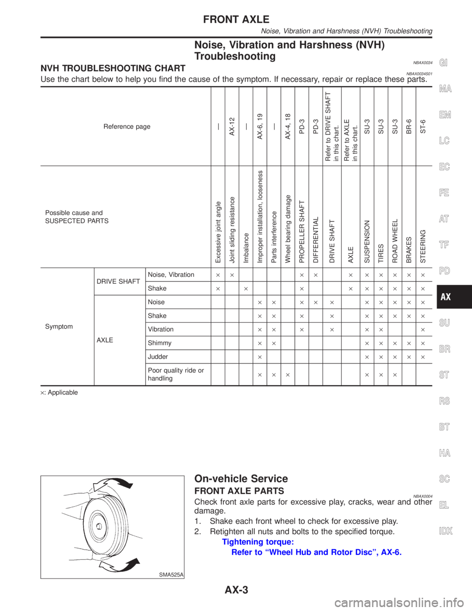
Noise, Vibration and Harshness (NVH)
Troubleshooting
NBAX0034NVH TROUBLESHOOTING CHARTNBAX0034S01Use the chart below to help you find the cause of the symptom. If necessary, repair or replace these parts.
Reference pageÐ
AX-12
Ð
AX-6, 19
Ð
AX-4, 18
PD-3
PD-3
Refer to DRIVE SHAFT
in this chart.
Refer to AXLE
in this chart.
SU-3
SU-3
SU-3
BR-6
ST-6
Possible cause and
SUSPECTED PARTS
Excessive joint angle
Joint sliding resistance
Imbalance
Improper installation, looseness
Parts interference
Wheel bearing damage
PROPELLER SHAFT
DIFFERENTIAL
DRIVE SHAFT
AXLE
SUSPENSION
TIRES
ROAD WHEEL
BRAKES
STEERING
SymptomDRIVE SHAFTNoise, Vibration´´ ´´ ´ ´´´´´
Shake´ ´ ´ ´ ´´´´´
AXLENoise´´ ´´ ´ ´´´´´
Shake´´ ´ ´ ´´´´´
Vibration´´ ´ ´ ´´ ´
Shimmy´´ ´´´´´
Judder´ ´´´´´
Poor quality ride or
handling´´´ ´´´
´: Applicable
SMA525A
On-vehicle Service
FRONT AXLE PARTSNBAX0004Check front axle parts for excessive play, cracks, wear and other
damage.
1. Shake each front wheel to check for excessive play.
2. Retighten all nuts and bolts to the specified torque.
Tightening torque:
Refer to ªWheel Hub and Rotor Discº, AX-6.
GI
MA
EM
LC
EC
FE
AT
TF
PD
SU
BR
ST
RS
BT
HA
SC
EL
IDX
FRONT AXLE
Noise, Vibration and Harshness (NVH) Troubleshooting
AX-3
Page 392 of 2395
Supplemental Restraint System (SRS) ªAIR
BAGº and ªSEAT BELT PRE-TENSIONERº
NBBR0001The Supplemental Restraint System such as ªAIR BAGº and ªSEAT BELT PRE-TENSIONERº used along with
a seat belt, helps to reduce the risk or severity of injury to the driver and front passenger for certain types of
collision. The SRS system composition which is available to INFINITI QX4 is as follows:
IFor a frontal collision
The Supplemental Restraint System consists of driver air bag module (located in the center of the steer-
ing wheel), front passenger air bag module (located on the instrument panel on passenger side), seat belt
pre-tensioners, a diagnosis sensor unit, warning lamp, wiring harness and spiral cable.
IFor a side collision
The Supplemental Restraint System consists of side air bag module (located in the outer side of front seat),
satellite sensor, diagnosis sensor unit (one of components of air bags for a frontal collision), wiring harness,
warning lamp (one of components of air bags for a frontal collision).
Information necessary to service the system safely is included in theRS sectionof this Service Manual.
WARNING:
ITo avoid rendering the SRS inoperative, which could increase the risk of personal injury or death
in the event of a collision which would result in air bag inflation, all maintenance must be performed
by an authorized INFINITI dealer.
IImproper maintenance, including incorrect removal and installation of the SRS, can lead to per-
sonal injury caused by unintentional activation of the system. For removal of Spiral Cable and Air
Bag Module, see the RS section.
IDo not use electrical test equipment on any circuit related to the SRS unless instructed to in this
Service Manual. Spiral cable and wiring harnesses covered with yellow insulation tape either just
before the harness connectors or for the complete harness are related to the SRS.
SBR686C
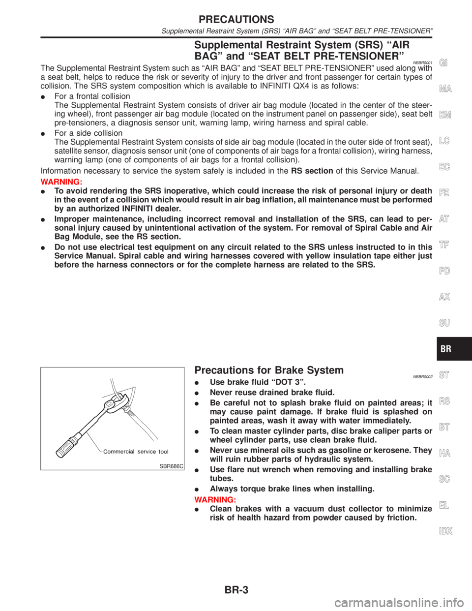
Precautions for Brake SystemNBBR0002IUse brake fluid ªDOT 3º.
INever reuse drained brake fluid.
IBe careful not to splash brake fluid on painted areas; it
may cause paint damage. If brake fluid is splashed on
painted areas, wash it away with water immediately.
ITo clean master cylinder parts, disc brake caliper parts or
wheel cylinder parts, use clean brake fluid.
INever use mineral oils such as gasoline or kerosene. They
will ruin rubber parts of hydraulic system.
IUse flare nut wrench when removing and installing brake
tubes.
IAlways torque brake lines when installing.
WARNING:
IClean brakes with a vacuum dust collector to minimize
risk of health hazard from powder caused by friction.
GI
MA
EM
LC
EC
FE
AT
TF
PD
AX
SU
ST
RS
BT
HA
SC
EL
IDX
PRECAUTIONS
Supplemental Restraint System (SRS) ªAIR BAGº and ªSEAT BELT PRE-TENSIONERº
BR-3
Page 411 of 2395
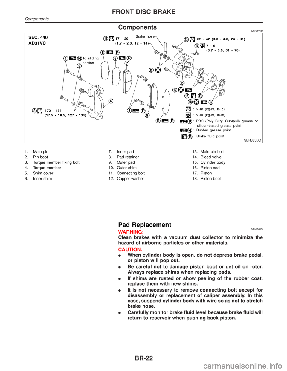
ComponentsNBBR0031
SBR385DC
1. Main pin
2. Pin boot
3. Torque member fixing bolt
4. Torque member
5. Shim cover
6. Inner shim7. Inner pad
8. Pad retainer
9. Outer pad
10. Outer shim
11. Connecting bolt
12. Copper washer13. Main pin bolt
14. Bleed valve
15. Cylinder body
16. Piston seal
17. Piston
18. Piston boot
Pad ReplacementNBBR0032WARNING:
Clean brakes with a vacuum dust collector to minimize the
hazard of airborne particles or other materials.
CAUTION:
IWhen cylinder body is open, do not depress brake pedal,
or piston will pop out.
IBe careful not to damage piston boot or get oil on rotor.
Always replace shims when replacing pads.
IIf shims are rusted or show peeling of the rubber coat,
replace them with new shims.
IIt is not necessary to remove connecting bolt except for
disassembly or replacement of caliper assembly. In this
case, suspend cylinder body with wire so as not to stretch
brake hose.
ICarefully monitor brake fluid level because brake fluid will
return to reservoir when pushing back piston.
FRONT DISC BRAKE
Components
BR-22
Page 1994 of 2395
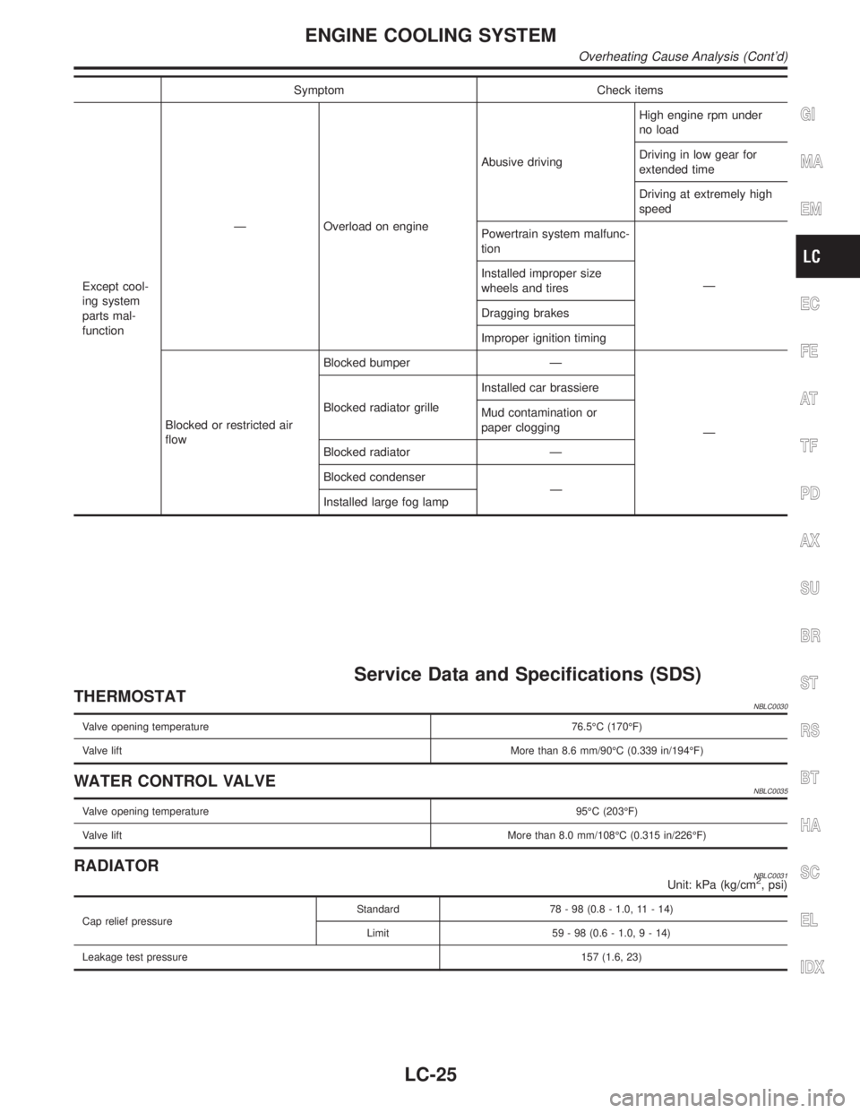
Symptom Check items
Except cool-
ing system
parts mal-
functionÐ Overload on engineAbusive drivingHigh engine rpm under
no load
Driving in low gear for
extended time
Driving at extremely high
speed
Powertrain system malfunc-
tion
Ð Installed improper size
wheels and tires
Dragging brakes
Improper ignition timing
Blocked or restricted air
flowBlocked bumper Ð
Ð Blocked radiator grilleInstalled car brassiere
Mud contamination or
paper clogging
Blocked radiator Ð
Blocked condenser
Ð
Installed large fog lamp
Service Data and Specifications (SDS)
THERMOSTATNBLC0030
Valve opening temperature76.5ÉC (170ÉF)
Valve liftMore than 8.6 mm/90ÉC (0.339 in/194ÉF)
WATER CONTROL VALVENBLC0035
Valve opening temperature95ÉC (203ÉF)
Valve liftMore than 8.0 mm/108ÉC (0.315 in/226ÉF)
RADIATORNBLC0031Unit: kPa (kg/cm2, psi)
Cap relief pressureStandard 78 - 98 (0.8 - 1.0, 11 - 14)
Limit 59 - 98 (0.6 - 1.0,9-14)
Leakage test pressure157 (1.6, 23)
GI
MA
EM
EC
FE
AT
TF
PD
AX
SU
BR
ST
RS
BT
HA
SC
EL
IDX
ENGINE COOLING SYSTEM
Overheating Cause Analysis (Cont'd)
LC-25