dimensions INFINITI QX4 2001 Factory User Guide
[x] Cancel search | Manufacturer: INFINITI, Model Year: 2001, Model line: QX4, Model: INFINITI QX4 2001Pages: 2395, PDF Size: 43.2 MB
Page 2050 of 2395

SPD194A
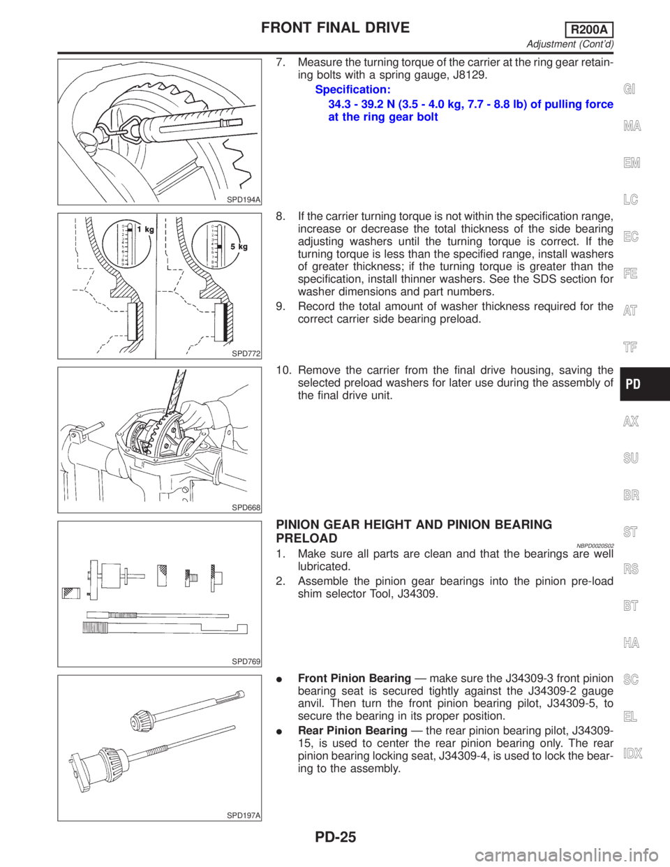
7. Measure the turning torque of the carrier at the ring gear retain-
ing bolts with a spring gauge, J8129.
Specification:
34.3 - 39.2 N (3.5 - 4.0 kg, 7.7 - 8.8 lb) of pulling force
at the ring gear bolt
SPD772
8. If the carrier turning torque is not within the specification range,
increase or decrease the total thickness of the side bearing
adjusting washers until the turning torque is correct. If the
turning torque is less than the specified range, install washers
of greater thickness; if the turning torque is greater than the
specification, install thinner washers. See the SDS section for
washer dimensions and part numbers.
9. Record the total amount of washer thickness required for the
correct carrier side bearing preload.
SPD668
10. Remove the carrier from the final drive housing, saving the
selected preload washers for later use during the assembly of
the final drive unit.
SPD769
PINION GEAR HEIGHT AND PINION BEARING
PRELOAD
NBPD0020S021. Make sure all parts are clean and that the bearings are well
lubricated.
2. Assemble the pinion gear bearings into the pinion pre-load
shim selector Tool, J34309.
SPD197A
IFront Pinion BearingÐ make sure the J34309-3 front pinion
bearing seat is secured tightly against the J34309-2 gauge
anvil. Then turn the front pinion bearing pilot, J34309-5, to
secure the bearing in its proper position.
IRear Pinion BearingÐ the rear pinion bearing pilot, J34309-
15, is used to center the rear pinion bearing only. The rear
pinion bearing locking seat, J34309-4, is used to lock the bear-
ing to the assembly.
GI
MA
EM
LC
EC
FE
AT
TF
AX
SU
BR
ST
RS
BT
HA
SC
EL
IDX
FRONT FINAL DRIVER200A
Adjustment (Cont'd)
PD-25
Page 2220 of 2395

SMA525A
On-vehicle Service
FRONT SUSPENSION PARTSNBSU0005Check front axle and front suspension parts for excessive play,
cracks, wear and other damage.
1. Shake each front wheel to check for excessive play.
2. Retighten all axle and suspensions nuts and bolts to the speci-
fied torque.
Tightening torque:
Refer to ªComponentsº, SU-8.
SFA392B
3. Check strut (shock absorber) for oil leakage and other dam-
age.
4. Check suspension ball joint for grease leakage and ball joint
dust cover for cracks and other damage.
If ball joint dust cover is cracked or damaged, replace ball joint
assembly.
5. Check suspension ball joint end play.
a. Jack up front of vehicle and set the stands.
b. Clamp dial indicator onto transverse link and place indicator tip
on lower edge of brake caliper.
c. Make sure front wheels are straight and brake pedal is
depressed.
SFA745B
d. Place a pry bar between transverse link and knuckle.
e. While raising and releasing pry bar, observe maximum dial
indicator value.
Vertical end play:
0mm(0in)
If ball joint vertical end play exists, remove lower ball joint
assembly and recheck the ball joint. Refer to ªTranverse Link
and Lower Ball Jointº, SU-11.
SFA746B
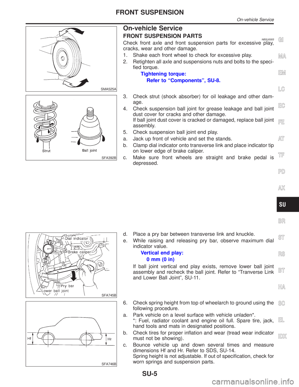
6. Check spring height from top of wheelarch to ground using the
following procedure.
a. Park vehicle on a level surface with vehicle unladen*.
*: Fuel, radiator coolant and engine oil full. Spare tire, jack,
hand tools and mats in designated positions.
b. Check tires for proper inflation and wear (tread wear indicator
must not be showing).
c. Bounce vehicle up and down several times and measure
dimensions Hf and Hr. Refer to SDS, SU-14.
Spring height is not adjustable. If out of specification, check for
worn springs and suspension parts.
GI
MA
EM
LC
EC
FE
AT
TF
PD
AX
BR
ST
RS
BT
HA
SC
EL
IDX
FRONT SUSPENSION
On-vehicle Service
SU-5