dimensions INFINITI QX4 2001 Factory Service Manual
[x] Cancel search | Manufacturer: INFINITI, Model Year: 2001, Model line: QX4, Model: INFINITI QX4 2001Pages: 2395, PDF Size: 43.2 MB
Page 530 of 2395

AlignmentNBBT0021IAll dimensions indicated in figures are actual ones.
IWhen using a tracking gauge, adjust both pointers to equal length. Then check the pointers and gauge
itself to make sure there is no free play.
IWhen a measuring tape is used, check to be sure there is no elongation, twisting or bending.
IMeasurements should be taken at the center of the mounting holes.
IAn asterisk (H) following the value at the measuring point indicates that the measuring point on the other
side is symmetrically the same value.
IThe coordinates of the measurement points are the distances measured from the standard line of ªXº, ªYº
and ªZº.
SBF874GD
GI
MA
EM
LC
EC
FE
AT
TF
PD
AX
SU
BR
ST
RS
HA
SC
EL
IDX
BODY (ALIGNMENT)
Alignment
BT-57
Page 1644 of 2395
ENGINE MECHANICAL
SECTION
EM
CONTENTS
PRECAUTIONS...............................................................3
Parts Requiring Angular Tightening .............................3
Liquid Gasket Application Procedure ..........................3
PREPARATION...............................................................4
Special Service Tools ..................................................4
Commercial Service Tools ...........................................6
NOISE, VIBRATION AND HARSHNESS (NVH)
TROUBLESHOOTING.....................................................8
NVH Troubleshooting - Engine Noise .........................9
OUTER COMPONENT PARTS.....................................10
Removal and Installation ...........................................10
TIGHTENING PROCEDURES...................................12
MEASUREMENT OF COMPRESSION PRESSURE....14
OIL PAN.........................................................................15
Components...............................................................15
Removal .....................................................................15
Installation ..................................................................18
TIMING CHAIN..............................................................20
Components...............................................................20
POSITION FOR APPLYING LIQUID GASKET............21
Removal .....................................................................23
Inspection...................................................................29
Installation ..................................................................29
OIL SEAL.......................................................................35
Replacement ..............................................................35
VALVE OIL SEAL.....................................................35
OIL SEAL INSTALLATION DIRECTION.....................36
FRONT OIL SEAL....................................................36
REAR OIL SEAL......................................................36
CYLINDER HEAD..........................................................38
Components...............................................................38
Removal .....................................................................39
Disassembly...............................................................41
Inspection...................................................................42
CYLINDER HEAD DISTORTION...............................42
CAMSHAFT VISUAL CHECK....................................42
CAMSHAFT RUNOUT..............................................42
CAMSHAFT CAM HEIGHT.......................................42
CAMSHAFT JOURNAL CLEARANCE........................42
CAMSHAFT END PLAY............................................43
CAMSHAFT SPROCKET RUNOUT...........................43
VALVE GUIDE CLEARANCE....................................43
VALVE GUIDE REPLACEMENT................................44
VALVE SEATS.........................................................45
REPLACING VALVE SEAT FOR SERVICE PARTS....45
VALVE DIMENSIONS...............................................46
VALVE SPRING.......................................................46
VALVE LIFTER........................................................46
Assembly ...................................................................47
Installation ..................................................................47
Valve Clearance.........................................................52
CHECKING.............................................................52
ADJUSTING............................................................54
ENGINE ASSEMBLY.....................................................57
Removal and Installation ...........................................57
REMOVAL...............................................................58
INSTALLATION........................................................60
CYLINDER BLOCK.......................................................61
Components...............................................................61
CYLINDER BLOCK HEATER....................................62
Removal and Installation ...........................................62
Disassembly...............................................................62
PISTON, CRANKSHAFT AND OIL JET......................62
Inspection...................................................................63
PISTON AND PISTON PIN CLEARANCE..................63
PISTON RING SIDE CLEARANCE............................64
PISTON RING END GAP..........................................64
CONNECTING ROD BEND AND TORSION...............65
CYLINDER BLOCK DISTORTION AND WEAR...........65
PISTON-TO-BORE CLEARANCE..............................66
CRANKSHAFT.........................................................67
BEARING CLEARANCE...........................................67
CONNECTING ROD BUSHING CLEARANCE
(SMALL END)
..........................................................70
DRIVE PLATE RUNOUT..........................................70
Assembly ...................................................................71
PISTON..................................................................71
OIL JET..................................................................71
CRANKSHAFT.........................................................71
REPLACEMENT OF PILOT CONVERTER.................74
DRIVE PLATE.........................................................74
GI
MA
LC
EC
FE
AT
TF
PD
AX
SU
BR
ST
RS
BT
HA
SC
EL
IDX
Page 1649 of 2395

Tool number
(Kent-Moore No.)
Tool nameDescription
KV10117100
(J3647-A)
Heated oxygen sensor
wrench
NT379
Loosening or tightening heated oxygen sensor
For 22 mm (0.87 in) hexagon nut
KV10114400
(J38365)
Heated oxygen sensor
wrench
NT636
Loosening or tightening rear heated oxygen sensor
a: 22 mm (0.87 in)
KV10117700
(J44716)
Ring gear stopper
NT822
Removing and installing crankshaft pulley
Commercial Service ToolsNBEM0004
Tool number
(Kent-Moore No.)
Tool nameDescription
Spark plug wrench
NT047
Removing and installing spark plug
Valve seat cutter set
NT048
Finishing valve seat dimensions
Piston ring expander
NT030
Removing and installing piston ring
Valve guide drift
NT015
Removing and installing valve guide
Intake & Exhaust:
a = 9.5 mm (0.374 in) dia.
b = 5.5 mm (0.217 in) dia.
PREPARATION
Special Service Tools (Cont'd)
EM-6
Page 1688 of 2395
SEM934C
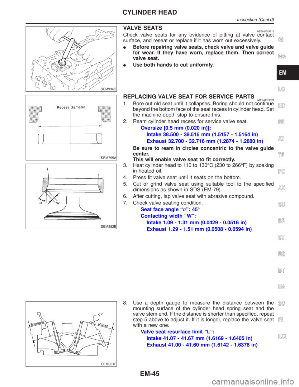
VALVE SEATSNBEM0019S10Check valve seats for any evidence of pitting at valve contact
surface, and reseat or replace if it has worn out excessively.
IBefore repairing valve seats, check valve and valve guide
for wear. If they have worn, replace them. Then correct
valve seat.
IUse both hands to cut uniformly.
SEM795A
REPLACING VALVE SEAT FOR SERVICE PARTSNBEM0019S111. Bore out old seat until it collapses. Boring should not continue
beyond the bottom face of the seat recess in cylinder head. Set
the machine depth stop to ensure this.
2. Ream cylinder head recess for service valve seat.
Oversize [0.5 mm (0.020 in)]:
Intake 38.500 - 38.516 mm (1.5157 - 1.5164 in)
Exhaust 32.700 - 32.716 mm (1.2874 - 1.2880 in)
Be sure to ream in circles concentric to the valve guide
center.
This will enable valve seat to fit correctly.
SEM892B
3. Heat cylinder head to 110 to 130ÉC (230 to 266ÉF) by soaking
in heated oil.
4. Press fit valve seat until it seats on the bottom.
5. Cut or grind valve seat using suitable tool to the specified
dimensions as shown in SDS (EM-79).
6. After cutting, lap valve seat with abrasive compound.
7. Check valve seating condition.
Seat face angle ªaº: 45É
Contacting width ªWº:
Intake 1.09 - 1.31 mm (0.0429 - 0.0516 in)
Exhaust 1.29 - 1.51 mm (0.0508 - 0.0594 in)
SEM621F
8. Use a depth gauge to measure the distance between the
mounting surface of the cylinder head spring seat and the
valve stem end. If the distance is shorter than specified, repeat
step 5 above to adjust it. If it is longer, replace the valve seat
with a new one.
Valve seat resurface limit ªLº:
Intake 41.07 - 41.67 mm (1.6169 - 1.6405 in)
Exhaust 41.00 - 41.60 mm (1.6142 - 1.6378 in)
GI
MA
LC
EC
FE
AT
TF
PD
AX
SU
BR
ST
RS
BT
HA
SC
EL
IDX
CYLINDER HEAD
Inspection (Cont'd)
EM-45
Page 1689 of 2395

SEM188A
VALVE DIMENSIONSNBEM0019S12Check dimensions of each valve. For dimensions, refer to SDS
(EM-76).
When valve head has been worn down to 0.5 mm (0.020 in) in
margin thickness, replace valve.
Grinding allowance for valve stem tip is 0.2 mm (0.008 in) or
less.
SEM288A
VALVE SPRINGNBEM0019S13SquarenessNBEM0019S13011. Measure dimension ªSº.
Out-of-square ªSº:
Less than 2.0 mm (0.079 in)
2. If it exceeds the limit, replace spring.
EM113
PressureNBEM0019S1302Check valve spring pressure at specified spring height.
Pressure:
Standard
202 N (20.6 kg, 45.4 lb) at height 37.0 mm (1.457 in)
Limit
More than 436 N (44.5 kg, 98.1 lb) at height 28.2
mm (1.110 in)
If it exceeds the limit, replace spring.
SEM960E
VALVE LIFTERNBEM0019S141. Check contact and sliding surfaces for wear or scratches.
SEM961E
2. Check diameter of valve lifter and valve lifter guide bore.
Valve lifter outer diameter:
34.960 - 34.975 mm (1.3764 - 1.3770 in)
CYLINDER HEAD
Inspection (Cont'd)
EM-46
Page 1746 of 2395
GENERAL INFORMATION
SECTION
GI
CONTENTS
PRECAUTIONS...............................................................3
Precautions ..................................................................3
PRECAUTIONS FOR SUPPLEMENTAL
RESTRAINT SYSTEM (SRS)²AIR BAG²AND
²SEAT BELT PRE-TENSIONER²
.................................3
PRECAUTIONS FOR IVIS (INFINITI VEHICLE
IMMOBILIZER SYSTEM - NATS)
.................................3
PRECAUTIONS FOR INFINITI COMMUNICATOR
(IVCS)
.......................................................................4
GENERAL PRECAUTIONS.........................................5
PRECAUTIONS FOR MULTIPORT FUEL
INJECTION SYSTEM OR ENGINE CONTROL
SYSTEM
...................................................................6
PRECAUTIONS FOR THREE WAY CATALYST...........6
PRECAUTIONS FOR HOSES.....................................7
PRECAUTIONS FOR ENGINE OILS...........................8
PRECAUTIONS FOR FUEL........................................8
PRECAUTIONS FOR AIR CONDITIONING..................8
HOW TO USE THIS MANUAL........................................9
HOW TO READ WIRING DIAGRAMS.......................... 11
Sample/Wiring Diagram - EXAMPL - ........................ 11
OPTIONAL SPLICE..................................................12
Description .................................................................13
CONNECTOR SYMBOLS.........................................15
HARNESS INDICATION...........................................16
COMPONENT INDICATION......................................16
SWITCH POSITIONS...............................................16
DETECTABLE LINES AND NON-DETECTABLE
LINES
.....................................................................17
MULTIPLE SWITCH.................................................18
REFERENCE AREA.................................................19
HOW TO CHECK TERMINAL.......................................21
Connector and Terminal Pin Kit.................................21
How to Probe Connectors .........................................21
PROBING FROM HARNESS SIDE............................21
PROBING FROM TERMINAL SIDE...........................21
How to Check Enlarged Contact Spring of
Terminal .....................................................................22
Waterproof Connector Inspection ..............................23
RUBBER SEAL INSPECTION...................................23
WIRE SEAL INSPECTION........................................23Terminal Lock Inspection ...........................................23
HOW TO PERFORM EFFICIENT DIAGNOSIS
FOR AN ELECTRICAL INCIDENT...............................24
Work Flow ..................................................................24
Incident Simulation Tests ...........................................25
INTRODUCTION......................................................25
VEHICLE VIBRATION..............................................25
HEAT SENSITIVE....................................................26
FREEZING..............................................................26
WATER INTRUSION................................................27
ELECTRICAL LOAD.................................................27
COLD OR HOT START UP.......................................27
Circuit Inspection .......................................................27
INTRODUCTION......................................................27
TESTING FOR²OPENS²IN THE CIRCUIT................28
TESTING FOR²SHORTS²IN THE CIRCUIT..............29
GROUND INSPECTION...........................................30
VOLTAGE DROP TESTS..........................................30
CONTROL UNIT CIRCUIT TEST...............................32
HOW TO FOLLOW TROUBLE DIAGNOSIS................34
How to Follow Test Groups in Trouble Diagnosis .....35
Key to Symbols Signifying Measurements or
Procedures.................................................................36
CONSULT-II CHECKING SYSTEM...............................38
Function and System Application ..............................38
Nickel Metal Hydride Battery Replacement...............39
Checking Equipment..................................................39
CONSULT-II Data Link Connector (DLC) Circuit ......40
INSPECTION PROCEDURE.....................................40
IDENTIFICATION INFORMATION................................41
Model Variation ..........................................................41
PREFIX AND SUFFIX DESIGNATIONS.....................41
Identification Number .................................................41
VEHICLE IDENTIFICATION NUMBER
ARRANGEMENT
.....................................................42
IDENTIFICATION PLATE..........................................42
ENGINE SERIAL NUMBER.......................................43
AUTOMATIC TRANSMISSION NUMBER...................43
TRANSFER SERIAL NUMBER..................................43
Dimensions ................................................................43
MA
EM
LC
EC
FE
AT
TF
PD
AX
SU
BR
ST
RS
BT
HA
SC
EL
IDX
Page 1788 of 2395

SGI136A
ENGINE SERIAL NUMBERNBGI0007S0203
MGI042A
AUTOMATIC TRANSMISSION NUMBERNBGI0007S0204
MGI043A
TRANSFER SERIAL NUMBERNBGI0007S0205
DimensionsNBGI0007S03Unit: mm (in)
Wagon
VQ35DE
Overall length 4,650 (183.1)
Overall width 1,840 (72.4)
Overall height1,730 (68.1)
1,795 (70.7)*
Front tread 1,540 (60.6)
Rear tread 1,545 (60.8)
Wheelbase 2,700 (106.3)
*: With luggage rack
MA
EM
LC
EC
FE
AT
TF
PD
AX
SU
BR
ST
RS
BT
HA
SC
EL
IDX
IDENTIFICATION INFORMATION
Identification Number (Cont'd)
GI-43
Page 1962 of 2395
Brake fluid change ...........................................BR-7
Brake fluid level .............................................MA-25
Brake fluid level and line check .......................BR-7
Brake hydraulic line ..........................................BR-9
Brake inspection ............................................MA-25
Brake lines and cables inspection .................MA-25
Brake lining wear temporary checking ..........MA-26
Brake master cylinder ....................................BR-16
Brake pedal ....................................................BR-14
Bulb specifications ........................................EL-456
Bumper, front ..................................................BT-12
Bumper, rear ...................................................BT-15
BYPS/V - Wiring diagram ....................EC-587, 594
C
Camshaft inspection ......................................EM-42
Camshaft position sensor (PHASE) .............EC-342
Canister-See EVAP canister ..........................EC-32
Center bearing assembly (propeller
shaft) .............................................................PD-9
Center bearing disassembly (propeller
shaft) .............................................................PD-7
Center case (Transfer) ..................................TF-123
CHARGE - Wiring diagram ............................SC-20
Charging system ............................................SC-19
Chassis and body maintenance ....................MA-21
CHIME - Wiring diagram...............................EL-127
CIGAR - Wiring diagram ...............................EL-148
Cigarette lighter.............................................EL-148
Circuit breaker.................................................EL-16
CKPS - Wiring diagram ................................EC-334
Closed loop control (Left bank) ....................EC-491
Closed loop control (Right bank) .................EC-491
Closed throttle position switch .....................EC-431
Clutch drum (Transfer) ..................................TF-125
Clutch force release limit adjustment .............TF-39
Clutch pressure switch (Transfer) .................TF-111
Coil spring (front)..............................................SU-8
Coil spring (rear) ............................................SU-18
Collision diagnosis..........................................RS-59
Combination lamp, front, removal and
installation ...................................................BT-12
Combination lamp, rear, removal and
installation ...................................................BT-35
Combination meter..........................................EL-94
Combination meter removal and instal-
lation - See Instrument panel ......................BT-21
Combination switch .........................................EL-28
COMPAS - Wiring diagram ...........................EL-111
Compass .......................................................EL-110
Component Location (auto A/C).....................HA-27
Compression pressure ...................................EM-14
Compressor clutch removal and
installation .................................................HA-150
Compressor precaution ....................................HA-6
Compressor special service tool ....................HA-10
Connecting rod...............................................EM-65
Connecting rod bearing clearance.................EM-69
Connecting rod bushing clearance ................EM-70Connector inspection .......................................GI-21
Console box - See Instrument panel ..............BT-21
CONSULT for ABS .........................................BR-43
CONSULT for all-mode 4WD ..........................TF-30
CONSULT for engine .....................................EC-81
CONSULT-II general information .....................GI-38
Control valve (A/T) ........................................AT-301
Control valve (Transfer) ................................TF-128
Converter housing installation .......................AT-278
Coolant mixture ratio......................................MA-12
Coolant replacement ......................................MA-14
Cooling circuit (engine) ...................................LC-10
``Crankcase emission control system -
See positive crankcase ventilation''............EC-38
Crankshaft ......................................................EM-67
Crankshaft position sensor (POS) ...............EC-334
Crankshaft position sensor (POS)
chipping ....................................................EC-517
Crankshaft position sensor (REF) ................EC-510
Cruise control - See ASCD ...........................EL-221
Cylinder block ................................................EM-61
Cylinder head .................................................EM-38
Cylinder head bolt tightening .........................EM-49
D
Data link connector for Consult......................EC-81
Daytime light system.......................................EL-46
Daytime running light - See Daytime
light system .................................................EL-46
DEF - Wiring diagram ...................................EL-153
Detonation sensor - See Knock sensor .......EC-328
Diagnostic trouble code (DTC) for OBD
system ....................................................EC-8, 60
Diagnostic trouble code (DTC) inspec-
tion priority chart .......................................EC-116
Differential carrier assembly.....................PD-30, 57
Differential carrier disassembly ......................PD-44
Differential gear oil replacement ....................MA-24
Dimensions ......................................................GI-43
D/LOCK - Wiring diagram .............................EL-256
Dome light - See Interior lamp .......................EL-88
Door glass .......................................................BT-18
Door lock .........................................................BT-18
Door mirror ......................................................BT-56
Door trim .........................................................BT-30
Door, front .......................................................BT-18
Door, rear ........................................................BT-20
Drive belt inspection ......................................MA-13
Drive chain (Transfer) ...................................TF-125
Drive pinion diff. inspection ......................PD-23, 47
Drive pinion height ...................................PD-25, 53
Drive plate runout ..........................................EM-70
Drive shaft (front)............................................AX-10
Dropping resistor (A/T) ..................................AT-167
DTC work support ..........................................EC-93
DTRL - Wiring diagram ...................................EL-51
GI
MA
EM
LC
EC
FE
AT
TF
PD
AX
SU
BR
ST
RS
BT
HA
SC
EL
ALPHABETICAL INDEX
IDX-3
Page 1964 of 2395
Fusible link ......................................................EL-16
G
Garage jack and safety stand .........................GI-46
Gauges............................................................EL-94
Generator - See Alternator .............................SC-28
Generic scan tool (GST) ................................EC-95
Glass ...............................................................BT-18
Glass hatch opener, electric .........................EL-178
Grease ............................................................MA-11
Ground distribution..........................................EL-17
H
Harness connector ............................................EL-5
Harness connector inspection .........................GI-21
Harness layout ..............................................EL-440
Hazard warning lamp ......................................EL-75
Headlamp ........................................................EL-31
Headlamp aiming control ................................EL-59
Headlining - See Roof trim .............................BT-32
Heated seat .......................................BT-43, EL-183
Height (Dimensions) ........................................GI-43
HFC134a (R134a) system precaution .............HA-2
HFC134a (R134a) system service
procedure ..................................................HA-144
HFC134a (R134a) system service tools ........HA-11
HFC134a system service equipment
precaution .....................................................HA-7
High clutch.....................................................AT-317
H/LAMP - Wiring diagram ...............................EL-36
Hood................................................................BT-12
Horn ..............................................................EL-147
HORN - Wiring diagram................................EL-147
How to erase DTC for OBD system...............EC-72
HSEAT - Wiring diagram...............................EL-183
I
IACV-AAC valve ...........................................EC-422
IATS - Wiring diagram ..................................EC-166
Identification .....................................................HA-4
Identification plate............................................GI-42
Idle air control valve (IACV) .........................EC-422
Idle mixture ratio.............................................EC-43
Idle speed .......................................................EC-43
IGN/SG - Wiring diagram .............................EC-501
Ignition control system .................................EC-499
Ignition timing .................................................EC-43
ILL - Wiring diagram .......................................EL-83
Illumination ......................................................EL-80
In vehicle sensor ..........................................HA-132
INFINITI COMMUNICATOR..........................EL-348
Infiniti communicator (IVCS) .........................EL-348
INJECT - Wiring diagram .............................EC-617
Injector ..........................................................EC-616Injector removal and installation ....................EC-41
Instrument panel .............................................BT-21
INT/L - Wiring diagram....................................EL-91
Intake air temparature sensor ......................EC-164
Intake door control linkage adjustment ..........HA-94
Intake door motor ...........................................HA-87
Intake manifold...............................................EM-12
Intake sensor ................................................HA-139
Integrated homelink transmitter ....................EL-325
Interior .............................................................BT-28
Interior lamp ....................................................EL-88
Interior lamp on-off control ..............................EL-89
Internal gear (Transfer) .................................TF-134
IVC-L - Wiring diagram.................................EC-453
IVC-R - Wiring diagram ................................EC-453
IVCS - Wiring diagram ..................................EL-359
IVCS-L - Wiring diagram ..............................EC-485
IVCS-R - Wiring diagram .............................EC-485
IVIS (Infiniti vehicle immobilizer
system) ......................................................EL-328
IVIS (Infiniti vehicle immobilizer sys-
tem) precautions ............................................GI-3
J
Jacking points ..................................................GI-45
Journal bearing assembly (propeller
shaft) .............................................................PD-9
Journal bearing disassembly (propeller
shaft) .............................................................PD-8
Junction box (J/B).........................................Foldout
K
Keyless entry system - See Multi-re-
mote control system ..................................EL-270
Knock sensor (KS) .......................................EC-328
Knuckle spindle ................................................AX-9
KS - Wiring diagram .....................................EC-330
L
Length (Dimensions) .......................................GI-43
License lamp ...................................................EL-61
Lifting points ....................................................GI-47
Limited slip diff. adjustment ............................PD-50
Limited slip diff. assembly ..............................PD-51
Limited slip diff. disassembly..........................PD-48
Limited slip diff. inspection .............................PD-49
Line pressure solenoid valve ........AT-147, 161, 167
Line pressure switch (Transfer) .....................TF-111
Line pressure test (A/T) ..................................AT-62
Liquid gasket application .................................EM-3
LOAD - Wiring diagram ................................EC-643
Location of electrical units ............................EL-436
Lock, door .......................................................BT-18
Low and reverse brake .................................AT-324
GI
MA
EM
LC
EC
FE
AT
TF
PD
AX
SU
BR
ST
RS
BT
HA
SC
EL
ALPHABETICAL INDEX
IDX-5
Page 1967 of 2395
S/VCSW - Wiring diagram ...........................EC-493
Swirl control valve control solenoid
valve .........................................................EC-458
Swirl control valve control vacuum
check switch .............................................EC-493
SWL/V - Wiring diagram ..............................EC-458
Symbols and abbreviations .............................GI-10
Symptom matrix chart...................................EC-118
System readiness test (SRT) code ................EC-61
T
2-4WD shift solenoid valve............................TF-111
Tachometer .....................................................EL-94
Tail lamp ..........................................................EL-61
TAIL/L - Wiring diagram ..................................EL-63
TCM circuit diagram ........................................AT-13
TCM inspection table ......................................AT-92
TFTS - Wiring diagram .................................EC-311
THEFT - Wiring diagram ...............................EL-300
Theft warning system....................................EL-294
Thermometer .................................................EL-110
Thermostat ......................................................LC-16
Three way catalyst function (Left bank) .......EC-347
Three way catalyst function (Right
bank) .........................................................EC-347
Three way catalyst precautions.........................GI-6
Throttle bodies ...............................................EM-12
Throttle position sensor (TPS) .....................EC-174
Throttle position sensor adjustment .............EC-101
Throttle position switch ...........EC-431, AT-184, 264
Tie-rod .............................................................ST-21
Tie-rod ball joints.............................................ST-21
Tightening torque of standard bolts.................GI-50
Timing chain ...................................................EM-20
Tire rotation ....................................................MA-24
Tire size ...........................................................GI-44
TLID - Wiring diagram ..................................EL-179
Tooth contact (front final drive 4WD) .............PD-29
Tooth contact diff. ...........................................PD-56
Torque converter installation .........................AT-278
Torque convertor clutch solenoid
valve ..................................................AT-152, 161
Tow truck towing ..............................................GI-47
Towing point.....................................................GI-49
TP/SW - Wiring diagram ..............................EC-434
TPS - Wiring diagram...................................EC-180
Transfer control unit inspection table..............TF-55
Transfer dropping resistor .............................TF-112
Transfer fluid replacement (Part time
4WD model) ...............................................MA-22
Transfer fluid temperature sensor .................TF-111
Transfer motor ...............................................TF-117
Transfer motor relay ......................................TF-113
Transfer serial number ....................................GI-43
TRANSMT - Wiring diagram .........................EL-325
Tread-FR&RR (Dimensions)............................GI-43
Trim .................................................................BT-28
Trouble diagnoses ...........................................GI-34
Trunk lid opener, electric...............................EL-178Turbine revolution sensor..............................AT-202
TURN - Wiring diagram ..................................EL-77
Turn signal lamp .............................................EL-75
Two trip detection logic ..................................EC-59
Two-pole lift .....................................................GI-47
U
Under body .....................................................BT-60
V
Vacuum cut valve ...........................................EC-32
Vacuum cut valve bypass valve.....EC-32, 585, 591
Vacuum hose (brake system).........................BR-21
Vacuum hose drawing (Engine control) .........EC-26
Valve clearance ..............................................EM-52
Valve guide.....................................................EM-43
Valve seat.......................................................EM-45
Valve spring....................................................EM-46
Vehicle identification number...........................GI-42
Vehicle recovery (freeing a stuck
vehicle) .........................................................GI-49
Vehicle speed sensor (VSS) ........................EC-417
VENT/V - Wiring diagram ............EC-376, 555, 576
Ventilation air filter ........................................HA-159
VIAS .............................................................EC-610
VIAS - Wiring diagram .................................EC-610
Viscosity number (SAE) .................................MA-12
VSS - Wiring diagram ..................................EC-420
W
Wait detection switch ....................................TF-112
WARN - Wiring diagram................................EL-115
Warning chime ..............................................EL-125
Warning lamps ..............................................EL-114
Washer, front .................................................EL-136
Washer, rear..................................................EL-141
Water pump ....................................................LC-12
Water temperature gauge ...............................EL-94
Weatherstrip - See Exterior ............................BT-35
Wheel balance ...............................................MA-24
Wheel bearing (front)........................................AX-4
Wheel bearing (rear) ......................................AX-18
Wheel hub (front)..............................................AX-6
Wheel sensors (ABS)...............................BR-56, 80
Wheel size .......................................................GI-44
Wheelarch height .............................................SU-5
Wheelbase (Dimensions) ................................GI-43
Wide open & closed throttle position
switch ........................................................EC-174
Width (Dimensions) .........................................GI-43
WINDOW - Wiring diagram ..........................EL-245
Window, door ..................................................BT-18
Window, rear side ...........................................BT-55
Window, side - See Rear side window ...........BT-55
ALPHABETICAL INDEX
IDX-8