elec INFINITI QX4 2001 Factory Service Manual
[x] Cancel search | Manufacturer: INFINITI, Model Year: 2001, Model line: QX4, Model: INFINITI QX4 2001Pages: 2395, PDF Size: 43.2 MB
Page 1623 of 2395
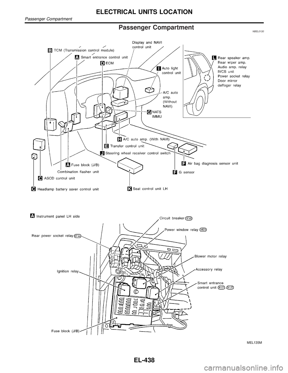
Passenger CompartmentNBEL0130
MEL135M
ELECTRICAL UNITS LOCATION
Passenger Compartment
EL-438
Page 1624 of 2395

MEL136M
GI
MA
EM
LC
EC
FE
AT
TF
PD
AX
SU
BR
ST
RS
BT
HA
SC
IDX
ELECTRICAL UNITS LOCATION
Passenger Compartment (Cont'd)
EL-439
Page 1642 of 2395
NBEL0145
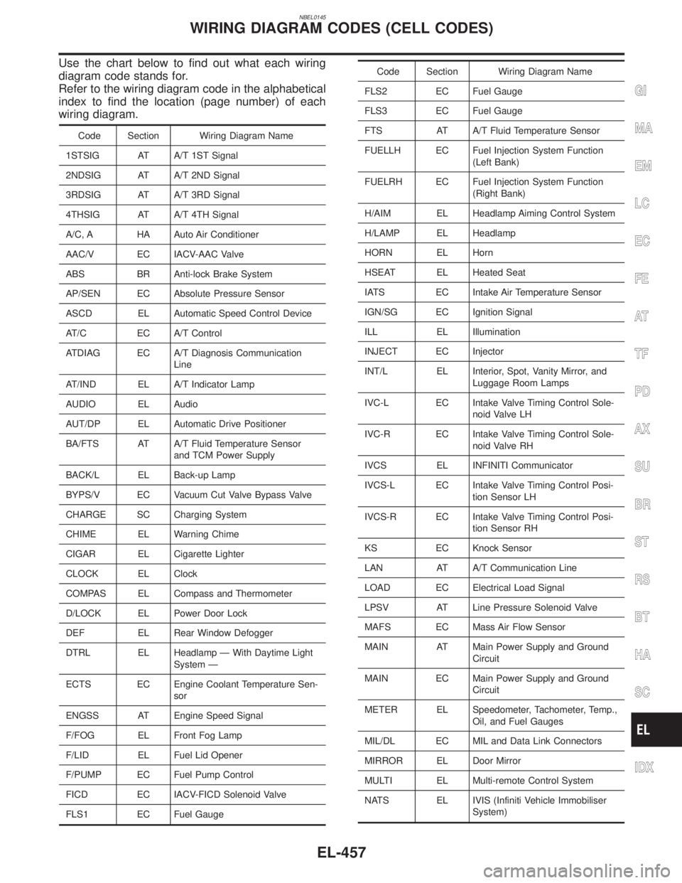
Use the chart below to find out what each wiring
diagram code stands for.
Refer to the wiring diagram code in the alphabetical
index to find the location (page number) of each
wiring diagram.
Code Section Wiring Diagram Name
1STSIG AT A/T 1ST Signal
2NDSIG AT A/T 2ND Signal
3RDSIG AT A/T 3RD Signal
4THSIG AT A/T 4TH Signal
A/C, A HA Auto Air Conditioner
AAC/V EC IACV-AAC Valve
ABS BR Anti-lock Brake System
AP/SEN EC Absolute Pressure Sensor
ASCD EL Automatic Speed Control Device
AT/C EC A/T Control
ATDIAG EC A/T Diagnosis Communication
Line
AT/IND EL A/T Indicator Lamp
AUDIO EL Audio
AUT/DP EL Automatic Drive Positioner
BA/FTS AT A/T Fluid Temperature Sensor
and TCM Power Supply
BACK/L EL Back-up Lamp
BYPS/V EC Vacuum Cut Valve Bypass Valve
CHARGE SC Charging System
CHIME EL Warning Chime
CIGAR EL Cigarette Lighter
CLOCK EL Clock
COMPAS EL Compass and Thermometer
D/LOCK EL Power Door Lock
DEF EL Rear Window Defogger
DTRL EL Headlamp Ð With Daytime Light
System Ð
ECTS EC Engine Coolant Temperature Sen-
sor
ENGSS AT Engine Speed Signal
F/FOG EL Front Fog Lamp
F/LID EL Fuel Lid Opener
F/PUMP EC Fuel Pump Control
FICD EC IACV-FICD Solenoid Valve
FLS1 EC Fuel Gauge
Code Section Wiring Diagram Name
FLS2 EC Fuel Gauge
FLS3 EC Fuel Gauge
FTS AT A/T Fluid Temperature Sensor
FUELLH EC Fuel Injection System Function
(Left Bank)
FUELRH EC Fuel Injection System Function
(Right Bank)
H/AIM EL Headlamp Aiming Control System
H/LAMP EL Headlamp
HORN EL Horn
HSEAT EL Heated Seat
IATS EC Intake Air Temperature Sensor
IGN/SG EC Ignition Signal
ILL EL Illumination
INJECT EC Injector
INT/L EL Interior, Spot, Vanity Mirror, and
Luggage Room Lamps
IVC-L EC Intake Valve Timing Control Sole-
noid Valve LH
IVC-R EC Intake Valve Timing Control Sole-
noid Valve RH
IVCS EL INFINITI Communicator
IVCS-L EC Intake Valve Timing Control Posi-
tion Sensor LH
IVCS-R EC Intake Valve Timing Control Posi-
tion Sensor RH
KS EC Knock Sensor
LAN AT A/T Communication Line
LOAD EC Electrical Load Signal
LPSV AT Line Pressure Solenoid Valve
MAFS EC Mass Air Flow Sensor
MAIN AT Main Power Supply and Ground
Circuit
MAIN EC Main Power Supply and Ground
Circuit
METER EL Speedometer, Tachometer, Temp.,
Oil, and Fuel Gauges
MIL/DL EC MIL and Data Link Connectors
MIRROR EL Door Mirror
MULTI EL Multi-remote Control System
NATS EL IVIS (Infiniti Vehicle Immobiliser
System)
GI
MA
EM
LC
EC
FE
AT
TF
PD
AX
SU
BR
ST
RS
BT
HA
SC
IDX
WIRING DIAGRAM CODES (CELL CODES)
EL-457
Page 1698 of 2395
SEM869EA
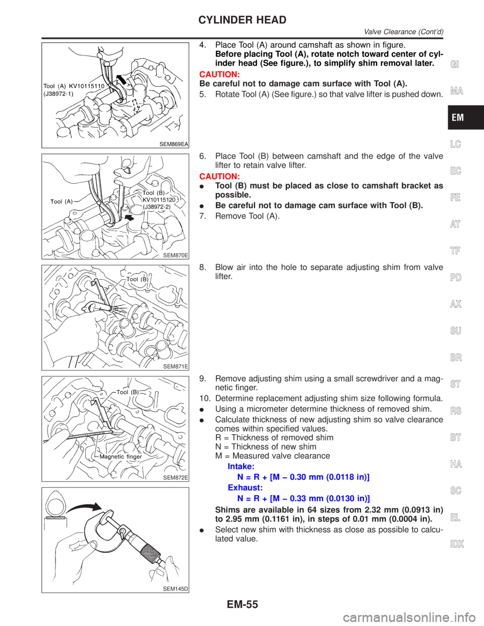
4. Place Tool (A) around camshaft as shown in figure.
Before placing Tool (A), rotate notch toward center of cyl-
inder head (See figure.), to simplify shim removal later.
CAUTION:
Be careful not to damage cam surface with Tool (A).
5. Rotate Tool (A) (See figure.) so that valve lifter is pushed down.
SEM870E
6. Place Tool (B) between camshaft and the edge of the valve
lifter to retain valve lifter.
CAUTION:
ITool (B) must be placed as close to camshaft bracket as
possible.
IBe careful not to damage cam surface with Tool (B).
7. Remove Tool (A).
SEM871E
8. Blow air into the hole to separate adjusting shim from valve
lifter.
SEM872E
SEM145D
9. Remove adjusting shim using a small screwdriver and a mag-
netic finger.
10. Determine replacement adjusting shim size following formula.
IUsing a micrometer determine thickness of removed shim.
ICalculate thickness of new adjusting shim so valve clearance
comes within specified values.
R = Thickness of removed shim
N = Thickness of new shim
M = Measured valve clearance
Intake:
N=R+[Mþ0.30 mm (0.0118 in)]
Exhaust:
N=R+[Mþ0.33 mm (0.0130 in)]
Shims are available in 64 sizes from 2.32 mm (0.0913 in)
to 2.95 mm (0.1161 in), in steps of 0.01 mm (0.0004 in).
ISelect new shim with thickness as close as possible to calcu-
lated value.
GI
MA
LC
EC
FE
AT
TF
PD
AX
SU
BR
ST
RS
BT
HA
SC
EL
IDX
CYLINDER HEAD
Valve Clearance (Cont'd)
EM-55
Page 1709 of 2395
SEM843E
SEM321AA
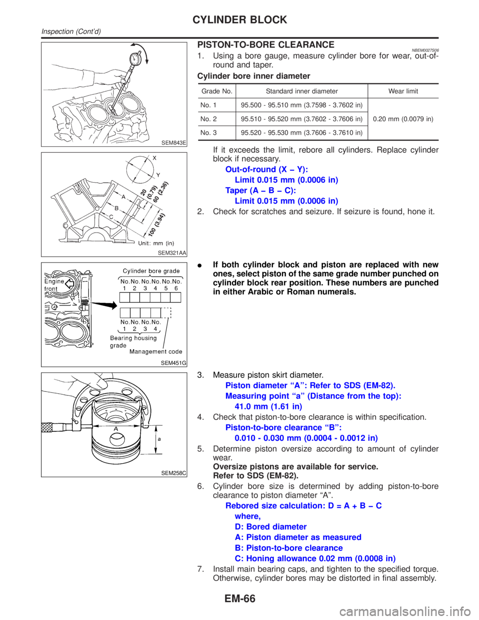
PISTON-TO-BORE CLEARANCENBEM0027S061. Using a bore gauge, measure cylinder bore for wear, out-of-
round and taper.
Cylinder bore inner diameter
Grade No. Standard inner diameter Wear limit
No. 1 95.500 - 95.510 mm (3.7598 - 3.7602 in)
0.20 mm (0.0079 in) No. 2 95.510 - 95.520 mm (3.7602 - 3.7606 in)
No. 3 95.520 - 95.530 mm (3.7606 - 3.7610 in)
If it exceeds the limit, rebore all cylinders. Replace cylinder
block if necessary.
Out-of-round (X þ Y):
Limit 0.015 mm (0.0006 in)
Taper (AþBþC):
Limit 0.015 mm (0.0006 in)
2. Check for scratches and seizure. If seizure is found, hone it.
SEM451G
IIf both cylinder block and piston are replaced with new
ones, select piston of the same grade number punched on
cylinder block rear position. These numbers are punched
in either Arabic or Roman numerals.
SEM258C
3. Measure piston skirt diameter.
Piston diameter ªAº: Refer to SDS (EM-82).
Measuring point ªaº (Distance from the top):
41.0 mm (1.61 in)
4. Check that piston-to-bore clearance is within specification.
Piston-to-bore clearance ªBº:
0.010 - 0.030 mm (0.0004 - 0.0012 in)
5. Determine piston oversize according to amount of cylinder
wear.
Oversize pistons are available for service.
Refer to SDS (EM-82).
6. Cylinder bore size is determined by adding piston-to-bore
clearance to piston diameter ªAº.
Rebored size calculation: D = A+BþC
where,
D: Bored diameter
A: Piston diameter as measured
B: Piston-to-bore clearance
C: Honing allowance 0.02 mm (0.0008 in)
7. Install main bearing caps, and tighten to the specified torque.
Otherwise, cylinder bores may be distorted in final assembly.
CYLINDER BLOCK
Inspection (Cont'd)
EM-66
Page 1711 of 2395
SEM845E
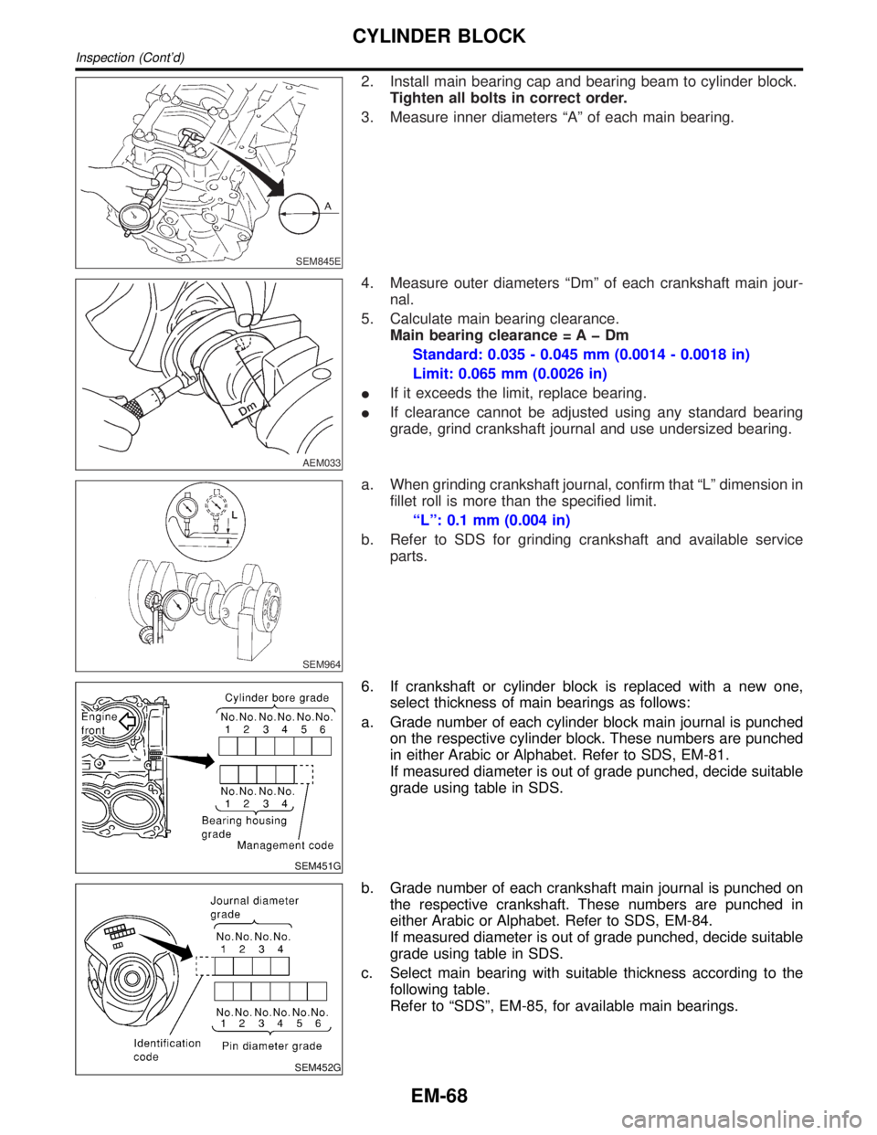
2. Install main bearing cap and bearing beam to cylinder block.
Tighten all bolts in correct order.
3. Measure inner diameters ªAº of each main bearing.
AEM033
4. Measure outer diameters ªDmº of each crankshaft main jour-
nal.
5. Calculate main bearing clearance.
Main bearing clearance = A þ Dm
Standard: 0.035 - 0.045 mm (0.0014 - 0.0018 in)
Limit: 0.065 mm (0.0026 in)
IIf it exceeds the limit, replace bearing.
IIf clearance cannot be adjusted using any standard bearing
grade, grind crankshaft journal and use undersized bearing.
SEM964
a. When grinding crankshaft journal, confirm that ªLº dimension in
fillet roll is more than the specified limit.
ªLº: 0.1 mm (0.004 in)
b. Refer to SDS for grinding crankshaft and available service
parts.
SEM451G
6. If crankshaft or cylinder block is replaced with a new one,
select thickness of main bearings as follows:
a. Grade number of each cylinder block main journal is punched
on the respective cylinder block. These numbers are punched
in either Arabic or Alphabet. Refer to SDS, EM-81.
If measured diameter is out of grade punched, decide suitable
grade using table in SDS.
SEM452G
b. Grade number of each crankshaft main journal is punched on
the respective crankshaft. These numbers are punched in
either Arabic or Alphabet. Refer to SDS, EM-84.
If measured diameter is out of grade punched, decide suitable
grade using table in SDS.
c. Select main bearing with suitable thickness according to the
following table.
Refer to ªSDSº, EM-85, for available main bearings.
CYLINDER BLOCK
Inspection (Cont'd)
EM-68
Page 1713 of 2395
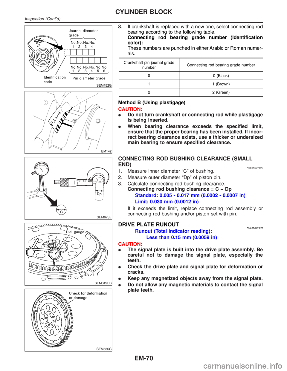
SEM452G
EM142
8. If crankshaft is replaced with a new one, select connecting rod
bearing according to the following table.
Connecting rod bearing grade number (Identification
color):
These numbers are punched in either Arabic or Roman numer-
als.
Crankshaft pin journal grade
numberConnecting rod bearing grade number
0 0 (Black)
1 1 (Brown)
2 2 (Green)
Method B (Using plastigage)
CAUTION:
IDo not turn crankshaft or connecting rod while plastigage
is being inserted.
IWhen bearing clearance exceeds the specified limit,
ensure that the proper bearing has been installed. If incor-
rect bearing clearance exists, use a thicker or undersized
main bearing to ensure specified clearance.
SEM673E
CONNECTING ROD BUSHING CLEARANCE (SMALL
END)
NBEM0027S091. Measure inner diameter ªCº of bushing.
2. Measure outer diameter ªDpº of piston pin.
3. Calculate connecting rod bushing clearance.
Connecting rod bushing clearance=CþDp
Standard: 0.005 - 0.017 mm (0.0002 - 0.0007 in)
Limit: 0.030 mm (0.0012 in)
If it exceeds the limit, replace connecting rod assembly or
connecting rod bushing and/or piston set with pin.
SEM849EB
SEM536G
DRIVE PLATE RUNOUTNBEM0027S11Runout (Total indicator reading):
Less than 0.15 mm (0.0059 in)
CAUTION:
IThe signal plate is built into the drive plate assembly. Be
careful not to damage the signal plate, especially the
teeth.
ICheck the drive plate and signal plate for deformation or
cracks.
IKeep any magnetized objects away from the signal plate.
IDo not allow any magnetic materials to contact the signal
plate teeth.
CYLINDER BLOCK
Inspection (Cont'd)
EM-70
Page 1715 of 2395
SEM177F
SEM456G
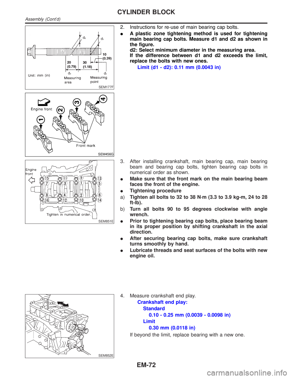
2. Instructions for re-use of main bearing cap bolts.
IA plastic zone tightening method is used for tightening
main bearing cap bolts. Measure d1 and d2 as shown in
the figure.
d2: Select minimum diameter in the measuring area.
If the difference between d1 and d2 exceeds the limit,
replace the bolts with new ones.
Limit (d1 - d2): 0.11 mm (0.0043 in)
SEM851E
3. After installing crankshaft, main bearing cap, main bearing
beam and bearing cap bolts, tighten bearing cap bolts in
numerical order as shown.
IMake sure that the front mark on the main bearing beam
faces the front of the engine.
ITightening procedure
a)Tighten all bolts to 32 to 38 N´m (3.3 to 3.9 kg-m, 24 to 28
ft-lb).
b)Turn all bolts 90 to 95 degrees clockwise with angle
wrench.
IPrior to tightening bearing cap bolts, place bearing beam
in its proper position by shifting crankshaft in the axial
direction.
IAfter securing bearing cap bolts, make sure crankshaft
turns smoothly by hand.
ILubricate threads and seat surfaces of the bolts with new
engine oil.
SEM852E
4. Measure crankshaft end play.
Crankshaft end play:
Standard
0.10 - 0.25 mm (0.0039 - 0.0098 in)
Limit
0.30 mm (0.0118 in)
If beyond the limit, replace bearing with a new one.
CYLINDER BLOCK
Assembly (Cont'd)
EM-72
Page 1744 of 2395
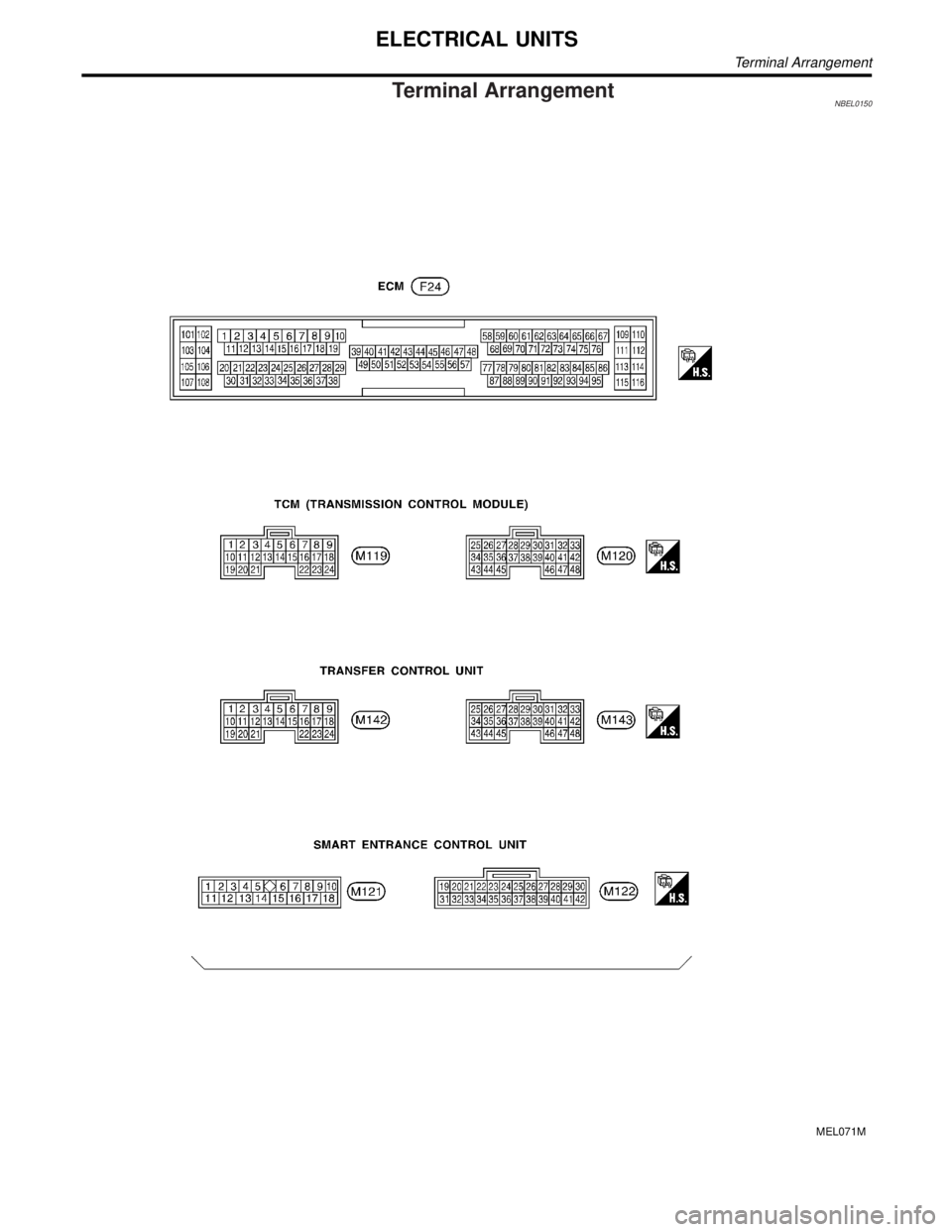
Terminal ArrangementNBEL0150
MEL071M
ELECTRICAL UNITS
Terminal Arrangement
Page 1746 of 2395
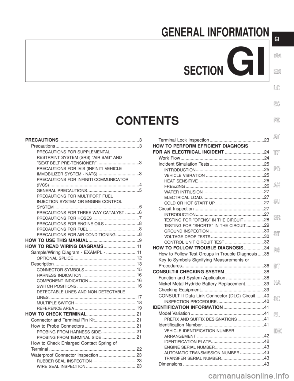
GENERAL INFORMATION
SECTION
GI
CONTENTS
PRECAUTIONS...............................................................3
Precautions ..................................................................3
PRECAUTIONS FOR SUPPLEMENTAL
RESTRAINT SYSTEM (SRS)²AIR BAG²AND
²SEAT BELT PRE-TENSIONER²
.................................3
PRECAUTIONS FOR IVIS (INFINITI VEHICLE
IMMOBILIZER SYSTEM - NATS)
.................................3
PRECAUTIONS FOR INFINITI COMMUNICATOR
(IVCS)
.......................................................................4
GENERAL PRECAUTIONS.........................................5
PRECAUTIONS FOR MULTIPORT FUEL
INJECTION SYSTEM OR ENGINE CONTROL
SYSTEM
...................................................................6
PRECAUTIONS FOR THREE WAY CATALYST...........6
PRECAUTIONS FOR HOSES.....................................7
PRECAUTIONS FOR ENGINE OILS...........................8
PRECAUTIONS FOR FUEL........................................8
PRECAUTIONS FOR AIR CONDITIONING..................8
HOW TO USE THIS MANUAL........................................9
HOW TO READ WIRING DIAGRAMS.......................... 11
Sample/Wiring Diagram - EXAMPL - ........................ 11
OPTIONAL SPLICE..................................................12
Description .................................................................13
CONNECTOR SYMBOLS.........................................15
HARNESS INDICATION...........................................16
COMPONENT INDICATION......................................16
SWITCH POSITIONS...............................................16
DETECTABLE LINES AND NON-DETECTABLE
LINES
.....................................................................17
MULTIPLE SWITCH.................................................18
REFERENCE AREA.................................................19
HOW TO CHECK TERMINAL.......................................21
Connector and Terminal Pin Kit.................................21
How to Probe Connectors .........................................21
PROBING FROM HARNESS SIDE............................21
PROBING FROM TERMINAL SIDE...........................21
How to Check Enlarged Contact Spring of
Terminal .....................................................................22
Waterproof Connector Inspection ..............................23
RUBBER SEAL INSPECTION...................................23
WIRE SEAL INSPECTION........................................23Terminal Lock Inspection ...........................................23
HOW TO PERFORM EFFICIENT DIAGNOSIS
FOR AN ELECTRICAL INCIDENT...............................24
Work Flow ..................................................................24
Incident Simulation Tests ...........................................25
INTRODUCTION......................................................25
VEHICLE VIBRATION..............................................25
HEAT SENSITIVE....................................................26
FREEZING..............................................................26
WATER INTRUSION................................................27
ELECTRICAL LOAD.................................................27
COLD OR HOT START UP.......................................27
Circuit Inspection .......................................................27
INTRODUCTION......................................................27
TESTING FOR²OPENS²IN THE CIRCUIT................28
TESTING FOR²SHORTS²IN THE CIRCUIT..............29
GROUND INSPECTION...........................................30
VOLTAGE DROP TESTS..........................................30
CONTROL UNIT CIRCUIT TEST...............................32
HOW TO FOLLOW TROUBLE DIAGNOSIS................34
How to Follow Test Groups in Trouble Diagnosis .....35
Key to Symbols Signifying Measurements or
Procedures.................................................................36
CONSULT-II CHECKING SYSTEM...............................38
Function and System Application ..............................38
Nickel Metal Hydride Battery Replacement...............39
Checking Equipment..................................................39
CONSULT-II Data Link Connector (DLC) Circuit ......40
INSPECTION PROCEDURE.....................................40
IDENTIFICATION INFORMATION................................41
Model Variation ..........................................................41
PREFIX AND SUFFIX DESIGNATIONS.....................41
Identification Number .................................................41
VEHICLE IDENTIFICATION NUMBER
ARRANGEMENT
.....................................................42
IDENTIFICATION PLATE..........................................42
ENGINE SERIAL NUMBER.......................................43
AUTOMATIC TRANSMISSION NUMBER...................43
TRANSFER SERIAL NUMBER..................................43
Dimensions ................................................................43
MA
EM
LC
EC
FE
AT
TF
PD
AX
SU
BR
ST
RS
BT
HA
SC
EL
IDX