fuel type INFINITI QX4 2001 Factory Service Manual
[x] Cancel search | Manufacturer: INFINITI, Model Year: 2001, Model line: QX4, Model: INFINITI QX4 2001Pages: 2395, PDF Size: 43.2 MB
Page 11 of 2395
Precautions for Supplemental Restraint System
(SRS) ªAIR BAGº and ªSEAT BELT
PRE-TENSIONERº
NBAT0001The supplemental Restraint System such as ªAIR BAGº and ªSEAT BELT PRE-TENSIONERº used along with
a seat belt, helps to reduce the risk or severity of injury to the driver and front passenger for certain types of
collision. The SRS system composition which is available to INFINITI QX4 is as follows:
IFor a frontal collision
The Supplemental Restraint System consists of driver air bag module (located in the center of the steer-
ing wheel), front passenger air bag module (located on the instrument panel on passenger side), seat belt
pre-tensioners, a diagnosis sensor unit, warning lamp, wiring harness and spiral cable.
IFor a side collision
The Supplemental Restraint System consists of front side air bag module (located in the outer side of front
seat), satellite sensor, diagnosis sensor unit (one of components of air bags for a frontal collision), wiring
harness, warning lamp (one of components of air bags for a frontal collision).
Information necessary to service the system safely is included in theRS sectionof this Service Manual.
WARNING:
ITo avoid rendering the SRS inoperative, which could increase the risk of personal injury or death
in the event of a collision which would result in air bag inflation, all maintenance must be performed
by an authorized INFINITI dealer.
IImproper maintenance, including incorrect removal and installation of the SRS, can lead to per-
sonal injury caused by unintentional activation of the system. For removal of Spiral Cable and Air
Bag Module, see the RS section.
IDo not use electrical test equipment on any circuit related to the SRS unless instructed to in this
Service Manual. Spiral cable and wiring harnesses covered with yellow insulation tape either just
before the harness connectors or for the complete harness are related to the SRS.
Precautions for On Board Diagnostic (OBD)
System of A/T and Engine
NBAT0002The ECM has an on board diagnostic system. It will light up the malfunction indicator lamp (MIL) to warn the
driver of a malfunction causing emission deterioration.
CAUTION:
IBe sure to turn the ignition switch ªOFFº and disconnect the negative battery terminal before any
repair or inspection work. The open/short circuit of related switches, sensors, solenoid valves, etc.
will cause the MIL to light up.
IBe sure to connect and lock the connectors securely after work. A loose (unlocked) connector will
cause the MIL to light up due to an open circuit. (Be sure the connector is free from water, grease,
dirt, bent terminals, etc.)
IBe sure to route and secure the harnesses properly after work. Interference of the harness with a
bracket, etc. may cause the MIL to light up due to a short circuit.
IBe sure to connect rubber tubes properly after work. A misconnected or disconnected rubber tube
may cause the MIL to light up due to a malfunction of the EGR system or fuel injection system,
etc.
IBe sure to erase the unnecessary malfunction information (repairs completed) from the TCM and
ECM before returning the vehicle to the customer.
SEF289H
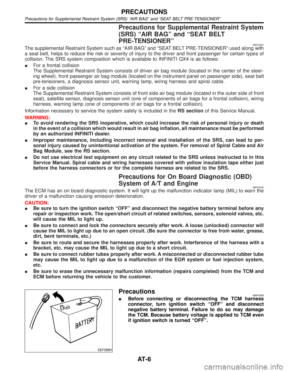
PrecautionsNBAT0003IBefore connecting or disconnecting the TCM harness
connector, turn ignition switch ªOFFº and disconnect
negative battery terminal. Failure to do so may damage
the TCM. Because battery voltage is applied to TCM even
if ignition switch is turned ªOFFº.
PRECAUTIONS
Precautions for Supplemental Restraint System (SRS) ªAIR BAGº and ªSEAT BELT PRE-TENSIONERº
AT-6
Page 549 of 2395
Supplemental Restraint System (SRS) ªAIR
BAGº and ªSEAT BELT PRE-TENSIONERº
NBEC0002The Supplemental Restraint System such as ªAIR BAGº and ªSEAT BELT PRE-TENSIONERº used along with
a seat belt, helps to reduce the risk or severity of injury to the driver and front passenger for certain types of
collision. The SRS system composition which is available to INFINITI QX4 is as follows:
IFor a frontal collision
The Supplemental Restraint System consists of driver air bag module (located in the center of the steer-
ing wheel), front passenger air bag module (located on the instrument panel on passenger side), seat belt
pre-tensioners, a diagnosis sensor unit, warning lamp, wiring harness and spiral cable.
IFor a side collision
The Supplemental Restraint System consists of front side air bag module (located in the outer side of front
seat), satellite sensor, diagnosis sensor unit (one of components of air bags for a frontal collision), wiring
harness, warning lamp (one of components of air bags for a frontal collision).
Information necessary to service the system safely is included in theRS sectionof this Service Manual.
WARNING:
ITo avoid rendering the SRS inoperative, which could increase the risk of personal injury or death
in the event of a collision which would result in air bag inflation, all maintenance must be performed
by an authorized INFINITI dealer.
IImproper maintenance, including incorrect removal and installation of the SRS, can lead to per-
sonal injury caused by unintentional activation of the system. For removal of Spiral Cable and Air
Bag Module, see the RS section.
IDo not use electrical test equipment on any circuit related to the SRS unless instructed to in this
Service Manual. Spiral cable and wiring harnesses covered with yellow insulation tape either just
before the harness connectors or for the complete harness are related to the SRS.
Precautions for On Board Diagnostic (OBD)
System of Engine and A/T
NBEC0003The ECM has an on board diagnostic system. It will light up the malfunction indicator lamp (MIL) to warn the
driver of a malfunction causing emission deterioration.
CAUTION:
IBe sure to turn the ignition switch OFF and disconnect the negative battery terminal before any
repair or inspection work. The open/short circuit of related switches, sensors, solenoid valves, etc.
will cause the MIL to light up.
IBe sure to connect and lock the connectors securely after work. A loose (unlocked) connector will
cause the MIL to light up due to the open circuit. (Be sure the connector is free from water, grease,
dirt, bent terminals, etc.)
ICertain systems and components, especially those related to OBD, may use a new style slide-
locking type harness connector. For description and how to disconnect, refer to EL-6, ªHARNESS
CONNECTOR (SLIDE-LOCKING TYPE)º.
IBe sure to route and secure the harnesses properly after work. The interference of the harness with
a bracket, etc. may cause the MIL to light up due to the short circuit.
IBe sure to connect rubber tubes properly after work. A misconnected or disconnected rubber tube
may cause the MIL to light up due to the malfunction of the fuel injection system, etc.
IBe sure to erase the unnecessary malfunction information (repairs completed) from the ECM and
TCM (Transmission control module) before returning the vehicle to the customer.
PRECAUTIONS
Supplemental Restraint System (SRS) ªAIR BAGº and ªSEAT BELT PRE-TENSIONERº
EC-14
Page 565 of 2395
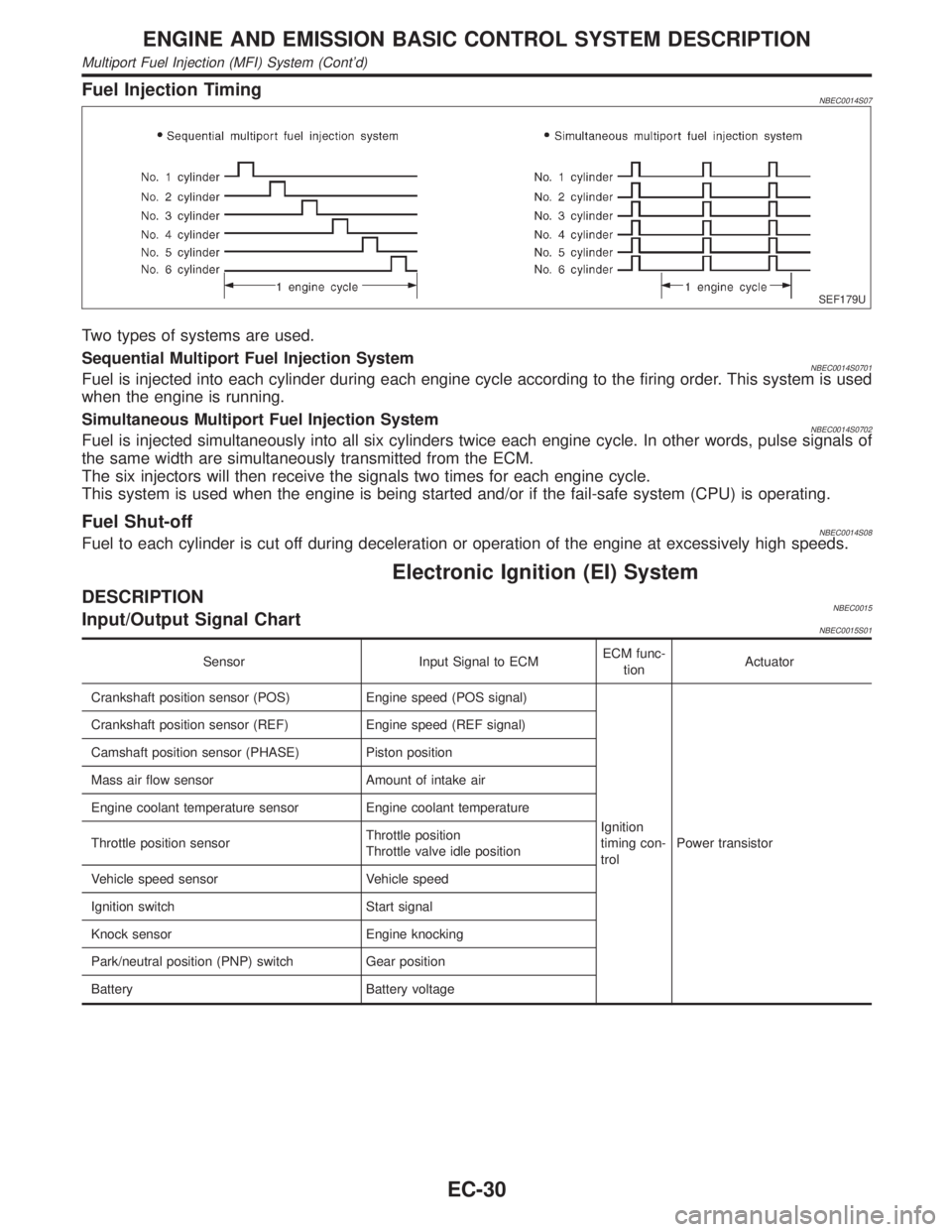
Fuel Injection TimingNBEC0014S07
SEF179U
Two types of systems are used.
Sequential Multiport Fuel Injection System
NBEC0014S0701Fuel is injected into each cylinder during each engine cycle according to the firing order. This system is used
when the engine is running.
Simultaneous Multiport Fuel Injection System
NBEC0014S0702Fuel is injected simultaneously into all six cylinders twice each engine cycle. In other words, pulse signals of
the same width are simultaneously transmitted from the ECM.
The six injectors will then receive the signals two times for each engine cycle.
This system is used when the engine is being started and/or if the fail-safe system (CPU) is operating.
Fuel Shut-offNBEC0014S08Fuel to each cylinder is cut off during deceleration or operation of the engine at excessively high speeds.
Electronic Ignition (EI) System
DESCRIPTIONNBEC0015Input/Output Signal ChartNBEC0015S01
Sensor Input Signal to ECMECM func-
tionActuator
Crankshaft position sensor (POS) Engine speed (POS signal)
Ignition
timing con-
trolPower transistor Crankshaft position sensor (REF) Engine speed (REF signal)
Camshaft position sensor (PHASE) Piston position
Mass air flow sensor Amount of intake air
Engine coolant temperature sensor Engine coolant temperature
Throttle position sensorThrottle position
Throttle valve idle position
Vehicle speed sensor Vehicle speed
Ignition switch Start signal
Knock sensor Engine knocking
Park/neutral position (PNP) switch Gear position
Battery Battery voltage
ENGINE AND EMISSION BASIC CONTROL SYSTEM DESCRIPTION
Multiport Fuel Injection (MFI) System (Cont'd)
EC-30
Page 1120 of 2395

SEF485T
Description=NBEC0346COMPONENT DESCRIPTIONNBEC0346S01The vacuum cut valve and vacuum cut valve bypass valve are
installed in parallel on the EVAP purge line between the fuel tank
and the EVAP canister.
The vacuum cut valve prevents the intake manifold vacuum from
being applied to the fuel tank.
The vacuum cut valve bypass valve is a solenoid type valve and
generally remains closed. It opens only for on board diagnosis.
The vacuum cut valve bypass valve responds to signals from the
ECM. When the ECM sends an ON (ground) signal, the valve is
opened. The vacuum cut valve is then bypassed to apply intake
manifold vacuum to the fuel tank.
EVAPORATIVE EMISSION SYSTEM DIAGRAMNBEC0346S02
SEF373Z
CONSULT-II Reference Value in Data Monitor
Mode
NBEC0347Specification data are reference values.
MONITOR ITEM CONDITION SPECIFICATION
VC/V BYPASS/VIIgnition switch: ON OFF
ECM Terminals and Reference ValueNBEC0681Specification data are reference values and are measured between each terminal and ground.
CAUTION:
Do not use ECM ground terminals when measuring input/output voltage. Doing so may result in dam-
age to the ECM's transistor. Use a ground other than ECM terminals, such as the ground.
TERMI-
NAL
NO.WIRE
COLORITEM CONDITION DATA (DC Voltage)
39 G/WVacuum cut valve
bypass valve[Ignition switch ªONº]BATTERY VOLTAGE
(11 - 14V)
GI
MA
EM
LC
FE
AT
TF
PD
AX
SU
BR
ST
RS
BT
HA
SC
EL
IDX
DTC P1490 VACUUM CUT VALVE BYPASS VALVE (CIRCUIT)
Description
EC-585
Page 1126 of 2395

SEF485T
DescriptionNBEC0353COMPONENT DESCRIPTIONNBEC0353S01The vacuum cut valve and vacuum cut valve bypass valve are
installed in parallel on the EVAP purge line between the fuel tank
and the EVAP canister.
The vacuum cut valve prevents the intake manifold vacuum from
being applied to the fuel tank.
The vacuum cut valve bypass valve is a solenoid type valve and
generally remains closed. It opens only for on board diagnosis.
The vacuum cut valve bypass valve responds to signals from the
ECM. When the ECM sends an ON (ground) signal, the valve is
opened. The vacuum cut valve is then bypassed to apply intake
manifold vacuum to the fuel tank.
EVAPORATIVE EMISSION SYSTEM DIAGRAMNBEC0353S02
SEF373Z
CONSULT-II Reference Value in Data Monitor
Mode
NBEC0354Specification data are reference values.
MONITOR ITEM CONDITION SPECIFICATION
VC/V BYPASS/VIIgnition switch: ON OFF
ECM Terminals and Reference ValueNBEC0682Specification data are reference values and are measured between each terminal and ground.
CAUTION:
Do not use ECM ground terminals when measuring input/output voltage. Doing so may result in dam-
age to the ECM's transistor. Use a ground other than ECM terminals, such as the ground.
TERMI-
NAL
NO.WIRE
COLORITEM CONDITION DATA (DC Voltage)
39 G/WVacuum cut valve
bypass valve[Ignition switch ªONº]BATTERY VOLTAGE
(11 - 14V)
GI
MA
EM
LC
FE
AT
TF
PD
AX
SU
BR
ST
RS
BT
HA
SC
EL
IDX
DTC P1491 VACUUM CUT VALVE BYPASS VALVE
Description
EC-591
Page 1160 of 2395
System DescriptionNBEC0392
Sensor Input Signal to ECMECM func-
tionActuator
Crankshaft position sensor (POS) Engine speed (POS signal)
Fuel pump
controlFuel pump relay Crankshaft position sensor (REF) Engine speed (REF signal)
Ignition switch Start signal
The ECM activates the fuel pump for several seconds after the ignition switch is turned on to improve engine
startability. If the ECM receives a 120É signal from the crankshaft position sensor (REF), it knows that the
engine is rotating, and causes the pump to operate. If the 120É signal is not received when the ignition switch
is on, the engine stalls. The ECM stops pump operation and prevents battery discharging, thereby improving
safety. The ECM does not directly drive the fuel pump. It controls the ON/OFF fuel pump relay, which in turn
controls the fuel pump.
Condition Fuel pump operation
Ignition switch is turned to ON. Operates for 1 second.
Engine running and cranking Operates.
When engine is stopped Stops in 1.5 seconds.
Except as shown aboveStops.
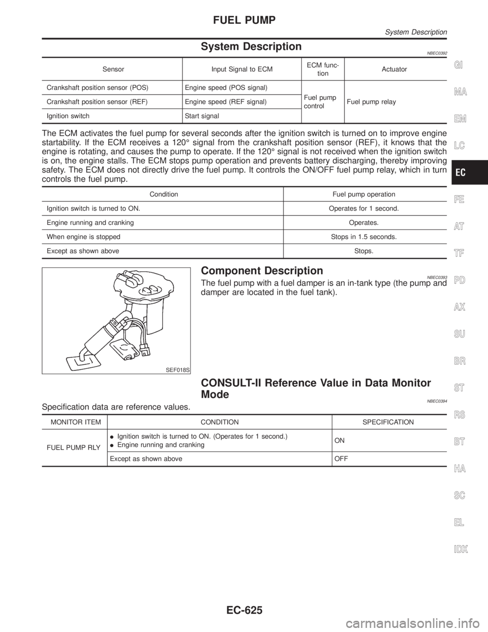
SEF018S
Component DescriptionNBEC0393The fuel pump with a fuel damper is an in-tank type (the pump and
damper are located in the fuel tank).
CONSULT-II Reference Value in Data Monitor
Mode
NBEC0394Specification data are reference values.
MONITOR ITEM CONDITION SPECIFICATION
FUEL PUMP RLYIIgnition switch is turned to ON. (Operates for 1 second.)
IEngine running and crankingON
Except as shown above OFF
GI
MA
EM
LC
FE
AT
TF
PD
AX
SU
BR
ST
RS
BT
HA
SC
EL
IDX
FUEL PUMP
System Description
EC-625
Page 1307 of 2395

SEL062WA
Fuel Warning Lamp Sensor CheckNBEL01661. Turn ignition switch ªOFFº.
2. Disconnect fuel level sensor unit harness connector B12.
3. Connect a resistor (80W) between fuel tank gauge unit harness
connector terminals 2 and 3.
4. Turn ignition switch ªONº.
The fuel warning lamp should come on.
NOTE:
ECM might store the 1st trip DTC P0180 during this inspection.
If the DTC is stored in ECM memory, erase the DTC after recon-
necting fuel tank gauge unit harness connector.
Refer to EC-60, ªHOW TO ERASE EMISSION-RELATED DIAG-
NOSTIC INFORMATIONº.
MEL425F
Electrical Components InspectionNBEL0051OIL PRESSURE SWITCH CHECKNBEL0051S02
Oil pressure
kPa (kg/cm2, psi)Continuity
Engine startMore than 10 - 20
(0.1-0.2,1-3)NO
Engine stopLess than 10 - 20
(0.1-0.2,1-3)YES
Check the continuity between the terminals of oil pressure switch
and body ground.
SEL901F
DIODE CHECKNBEL0051S03ICheck continuity using an ohmmeter.
IDiode is functioning properly if test results are as shown in the
figure at left.
ICheck diodes at the combination meter harness connector
instead of checking them on the combination meter assembly.
Refer to EL-115, ªWARNING LAMPº wiring diagrams.
NOTE:
Specification may vary depending on the type of tester. Before
performing this inspection, be sure to refer to the instruction
manual for the tester to be used.
WARNING LAMPS
Fuel Warning Lamp Sensor Check
EL-122
Page 1996 of 2395
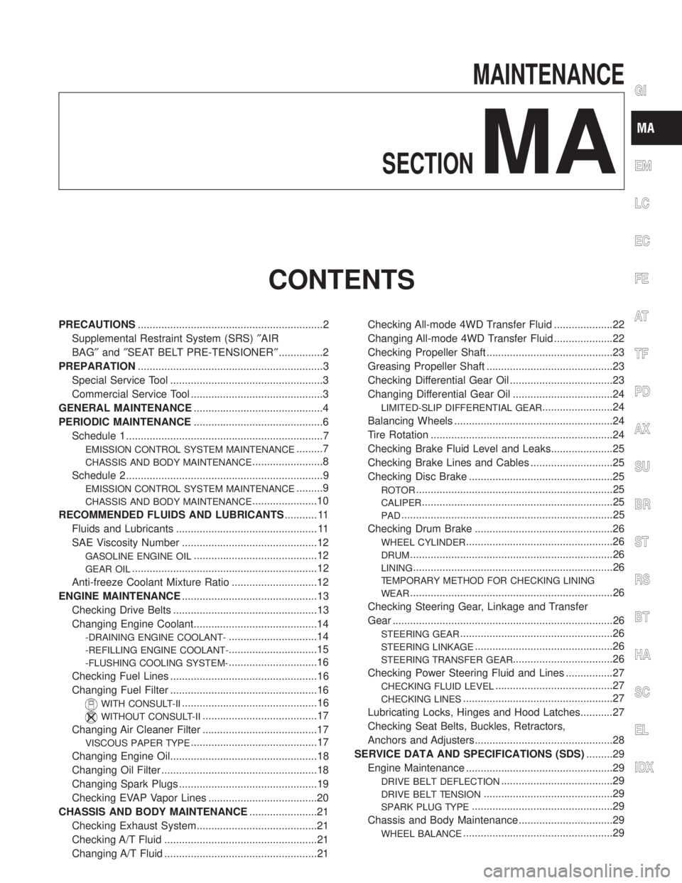
MAINTENANCE
SECTION
MA
CONTENTS
PRECAUTIONS...............................................................2
Supplemental Restraint System (SRS)²AIR
BAG²and²SEAT BELT PRE-TENSIONER²...............2
PREPARATION...............................................................3
Special Service Tool ....................................................3
Commercial Service Tool .............................................3
GENERAL MAINTENANCE............................................4
PERIODIC MAINTENANCE............................................6
Schedule 1 ...................................................................7
EMISSION CONTROL SYSTEM MAINTENANCE.........7
CHASSIS AND BODY MAINTENANCE........................8
Schedule 2 ...................................................................9
EMISSION CONTROL SYSTEM MAINTENANCE.........9
CHASSIS AND BODY MAINTENANCE......................10
RECOMMENDED FLUIDS AND LUBRICANTS........... 11
Fluids and Lubricants ................................................ 11
SAE Viscosity Number ..............................................12
GASOLINE ENGINE OIL..........................................12
GEAR OIL...............................................................12
Anti-freeze Coolant Mixture Ratio .............................12
ENGINE MAINTENANCE..............................................13
Checking Drive Belts .................................................13
Changing Engine Coolant..........................................14
-DRAINING ENGINE COOLANT-..............................14
-REFILLING ENGINE COOLANT-..............................15
-FLUSHING COOLING SYSTEM-..............................16
Checking Fuel Lines ..................................................16
Changing Fuel Filter ..................................................16
WITH CONSULT-II..............................................16
WITHOUT CONSULT-II.......................................17
Changing Air Cleaner Filter .......................................17
VISCOUS PAPER TYPE...........................................17
Changing Engine Oil..................................................18
Changing Oil Filter .....................................................18
Changing Spark Plugs ...............................................19
Checking EVAP Vapor Lines .....................................20
CHASSIS AND BODY MAINTENANCE.......................21
Checking Exhaust System.........................................21
Checking A/T Fluid ....................................................21
Changing A/T Fluid ....................................................21Checking All-mode 4WD Transfer Fluid ....................22
Changing All-mode 4WD Transfer Fluid ....................22
Checking Propeller Shaft ...........................................23
Greasing Propeller Shaft ...........................................23
Checking Differential Gear Oil ...................................23
Changing Differential Gear Oil ..................................24
LIMITED-SLIP DIFFERENTIAL GEAR........................24
Balancing Wheels ......................................................24
Tire Rotation ..............................................................24
Checking Brake Fluid Level and Leaks.....................25
Checking Brake Lines and Cables ............................25
Checking Disc Brake .................................................25
ROTOR...................................................................25
CALIPER.................................................................25
PAD........................................................................25
Checking Drum Brake ...............................................26
WHEEL CYLINDER..................................................26
DRUM.....................................................................26
LINING....................................................................26
TEMPORARY METHOD FOR CHECKING LINING
WEAR
.....................................................................26
Checking Steering Gear, Linkage and Transfer
Gear ...........................................................................26
STEERING GEAR....................................................26
STEERING LINKAGE...............................................26
STEERING TRANSFER GEAR..................................26
Checking Power Steering Fluid and Lines ................27
CHECKING FLUID LEVEL........................................27
CHECKING LINES...................................................27
Lubricating Locks, Hinges and Hood Latches...........27
Checking Seat Belts, Buckles, Retractors,
Anchors and Adjusters...............................................28
SERVICE DATA AND SPECIFICATIONS (SDS).........29
Engine Maintenance ..................................................29
DRIVE BELT DEFLECTION......................................29
DRIVE BELT TENSION............................................29
SPARK PLUG TYPE................................................29
Chassis and Body Maintenance ................................29
WHEEL BALANCE...................................................29
GI
EM
LC
EC
FE
AT
TF
PD
AX
SU
BR
ST
RS
BT
HA
SC
EL
IDX
Page 2002 of 2395
![INFINITI QX4 2001 Factory Service Manual Schedule 1NBMA0004S01EMISSION CONTROL SYSTEM MAINTENANCENBMA0004S0101
Abbreviations: R = Replace. I = Inspect. Correct or replace if necessary. [ ]: At the mileage intervals only
MAINTENANCE OPERATION INFINITI QX4 2001 Factory Service Manual Schedule 1NBMA0004S01EMISSION CONTROL SYSTEM MAINTENANCENBMA0004S0101
Abbreviations: R = Replace. I = Inspect. Correct or replace if necessary. [ ]: At the mileage intervals only
MAINTENANCE OPERATION](/img/42/57027/w960_57027-2001.png)
Schedule 1NBMA0004S01EMISSION CONTROL SYSTEM MAINTENANCENBMA0004S0101
Abbreviations: R = Replace. I = Inspect. Correct or replace if necessary. [ ]: At the mileage intervals only
MAINTENANCE OPERATIONMAINTENANCE INTERVAL
Reference
Section
- Page or
- Content Title Perform at number of miles, kilo-
meters or months, whichever
comes first.Miles x 1,000
(km x 1,000)
Months3.75
(6)
37.5
(12)
611.25
(18)
915
(24)
1218.75
(30)
1522.5
(36)
1826.25
(42)
2130
(48)
2433.75
(54)
2737.5
(60)
3041.25
(66)
3345
(72)
3648.75
(78)
3952.5
(84)
4256.25
(90)
4560
(96)
48
Drive beltsI* I* MA-13
Air cleaner filter NOTE (1) [R] [R] MA-17
EVAP vapor linesI* I* MA-20
Fuel linesI* I* MA-16
Fuel filter* NOTE (2)MA-16
Engine coolant NOTE (3)R* MA-14
Engine oil RRRRRRRRRRRRRRRRMA-18
Engine oil filter (Use part No.
15208-31U00 or equivalent.)RRRRRRRRRRRRRRRRMA-18
Spark plugs (PLATINUM-TIPPED
type)Replace every 105,000 miles (169,000 km) MA-19
Intake & exhaust valve clearance* NOTE (4)EM-52, ªValve
Clearanceº
NOTE:
(1) If operating mainly in dusty conditions, more frequent maintenance may be required.
(2) When the filter becomes clogged, the vehicle speed cannot be increased as the driver wishes. In such an event, replace the filter.
(3) After 60,000 miles (96,000 km) or 48 months, replace every 30,000 miles (48,000 km) or 24 months.
(4) If valve noise increases, inspect valve clearance.
HMaintenance items and intervals with ª*º are recommended by INFINITI for reliable vehicle operation. The owner need not perform such maintenance in order to maintain the
emission warranty or manufacturer recall liability. Other maintenance items and intervals are required.
GI
EM
LC
EC
FE
AT
TF
PD
AX
SU
BR
ST
RS
BT
HA
SC
EL
IDX
PERIODIC MAINTENANCE
Schedule 1
MA-7
Page 2004 of 2395
![INFINITI QX4 2001 Factory Service Manual Schedule 2NBMA0004S02EMISSION CONTROL SYSTEM MAINTENANCENBMA0004S0201
Abbreviations: R = Replace. I = Inspect. Correct or replace if necessary. [ ]: At the mileage intervals only
MAINTENANCE OPERATION INFINITI QX4 2001 Factory Service Manual Schedule 2NBMA0004S02EMISSION CONTROL SYSTEM MAINTENANCENBMA0004S0201
Abbreviations: R = Replace. I = Inspect. Correct or replace if necessary. [ ]: At the mileage intervals only
MAINTENANCE OPERATION](/img/42/57027/w960_57027-2003.png)
Schedule 2NBMA0004S02EMISSION CONTROL SYSTEM MAINTENANCENBMA0004S0201
Abbreviations: R = Replace. I = Inspect. Correct or replace if necessary. [ ]: At the mileage intervals only
MAINTENANCE OPERATIONMAINTENANCE INTERVAL
Reference Section
- Page
or
- Content Title Perform at number of miles, kilometers
or months, whichever comes first.Miles x 1,000
(km x 1,000)
Months7.5
(12)
615
(24)
1222.5
(36)
1830
(48)
2437.5
(60)
3045
(72)
3652.5
(84)
4260
(96)
48
Drive beltsI* I* MA-13
Air cleaner filter[R] [R] MA-17
EVAP vapor linesI* I* MA-20
Fuel linesI* I* MA-16
Fuel filter* NOTE (1)MA-16
Engine coolant NOTE (2)R* MA-14
Engine oilRRRRRRRRMA-18
Engine oil filter (Use part No. 15208-
31U00 or equivalent.)RRRRRRRRMA-18
Spark plugs (PLATINUM-TIPPED type) Replace every 105,000 miles (169,000 km) MA-19
Intake & exhaust valve clearance* NOTE (3)EM-52, ªValve Clear-
anceº
NOTE:
(1) When the filter becomes clogged, the vehicle speed cannot be increased as the driver wishes. In such an event, replace the filter.
(2) After 60,000 miles (96,000 km) or 48 months, replace every 30,000 miles (48,000 km) or 24 months.
(3) If valve noise increases, inspect valve clearance.
HMaintenance items and intervals with ª*º are recommended by INFINITI for reliable vehicle operation. The owner need not perform such maintenance in order to maintain the
emission warranty or manufacturer recall liability. Other maintenance items and intervals are required.
GI
EM
LC
EC
FE
AT
TF
PD
AX
SU
BR
ST
RS
BT
HA
SC
EL
IDX
PERIODIC MAINTENANCE
Schedule 2
MA-9