P0505 INFINITI QX4 2001 Factory Service Manual
[x] Cancel search | Manufacturer: INFINITI, Model Year: 2001, Model line: QX4, Model: INFINITI QX4 2001Pages: 2395, PDF Size: 43.2 MB
Page 540 of 2395
Possible Cause ........................................................ 411
Overall Function Check ........................................... 411
DTC P0464 FUEL LEVEL SENSOR CIRCUIT...........413
Component Description ...........................................413
On Board Diagnostic Logic......................................413
Possible Cause ........................................................413
DTC Confirmation Procedure ..................................413
Wiring Diagram ........................................................414
Diagnostic Procedure ..............................................415
DTC P0500 VEHICLE SPEED SENSOR (VSS).........417
Component Description ...........................................417
ECM Terminals and Reference Value .....................417
On Board Diagnosis Logic.......................................417
Possible Cause ........................................................418
DTC Confirmation Procedure ..................................418
Overall Function Check ...........................................418
Wiring Diagram ........................................................420
Diagnostic Procedure ..............................................421
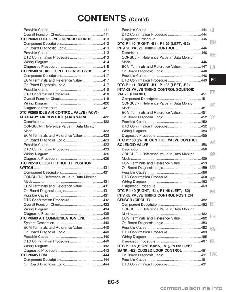
DTC P0505 IDLE AIR CONTROL VALVE (IACV) -
AUXILIARY AIR CONTROL (AAC) VALVE...............422
Description ...............................................................422
CONSULT-II Reference Value in Data Monitor
Mode ........................................................................423
ECM Terminals and Reference Value .....................423
On Board Diagnosis Logic.......................................423
Possible Cause ........................................................423
DTC Confirmation Procedure ..................................423
Wiring Diagram ........................................................425
Diagnostic Procedure ..............................................426
DTC P0510 CLOSED THROTTLE POSITION
SWITCH.......................................................................431
Component Description ...........................................431
CONSULT-II Reference Value in Data Monitor
Mode ........................................................................431
ECM Terminals and Reference Value .....................431
On Board Diagnosis Logic.......................................431
Possible Cause ........................................................431
DTC Confirmation Procedure ..................................432
Overall Function Check ...........................................432
Wiring Diagram ........................................................434
Diagnostic Procedure ..............................................435
DTC P0600 A/T COMMUNICATION LINE..................440
System Description ..................................................440
ECM Terminals and Reference Value .....................440
On Board Diagnosis Logic.......................................440
Possible Cause ........................................................440
DTC Confirmation Procedure ..................................440
Wiring Diagram ........................................................442
Diagnostic Procedure ..............................................443
DTC P0605 ECM.........................................................444
Component Description ...........................................444
On Board Diagnosis Logic.......................................444Possible Cause ........................................................444
DTC Confirmation Procedure ..................................444
Diagnostic Procedure ..............................................445
DTC P1110 (RIGHT, -B1), P1135 (LEFT, -B2)
INTAKE VALVE TIMING CONTROL..........................446
Description ...............................................................446
CONSULT-II Reference Value in Data Monitor
Mode ........................................................................446
ECM Terminals and Reference Value .....................447
On Board Diagnosis Logic.......................................448
Possible Cause ........................................................448
DTC Confirmation Procedure ..................................449
D T C P 1111(RIGHT, -B1), P1136 (LEFT, -B2)
INTAKE VALVE TIMING CONTROL SOLENOID
VALVE (CIRCUIT)........................................................451
Component Description ...........................................451
CONSULT-II Reference Value in Data Monitor
Mode ........................................................................451
ECM Terminals and Reference Value .....................451
On Board Diagnosis Logic.......................................452
Possible Cause ........................................................452
DTC Confirmation Procedure ..................................452
Wiring Diagram ........................................................453
Diagnostic Procedure ..............................................455
DTC P1130 SWIRL CONTROL VALVE CONTROL
SOLENOID VALVE......................................................458
Description ...............................................................458
CONSULT-II Reference Value in Data Monitor
Mode ........................................................................459
ECM Terminals and Reference Value .....................459
On Board Diagnosis Logic.......................................459
Possible Cause ........................................................460
DTC Confirmation Procedure ..................................460
Wiring Diagram ........................................................462
Diagnostic Procedure ..............................................463
DTC P1140 (RIGHT, -B1), P1145 (LEFT, -B2)
INTAKE VALVE TIMING CONTROL POSITION
SENSOR (CIRCUIT)....................................................482
Component Description ...........................................482
CONSULT-II Reference Value in Data Monitor
Mode ........................................................................482
ECM Terminals and Reference Value .....................482
On Board Diagnosis Logic.......................................483
Possible Cause ........................................................483
DTC Confirmation Procedure ..................................483
Wiring Diagram ........................................................485
Diagnostic Procedure ..............................................487
DTC P1148 (RIGHT BANK, -B1), P1168 (LEFT
BANK, -B2) CLOSED LOOP CONTROL...................491
On Board Diagnosis Logic.......................................491
Possible Cause ........................................................491
DTC Confirmation Procedure ..................................491GI
MA
EM
LC
FE
AT
TF
PD
AX
SU
BR
ST
RS
BT
HA
SC
EL
IDX
CONTENTS(Cont'd)
EC-5
Page 544 of 2395
Items
(CONSULT-II screen terms)DTC*1 Reference page
FUEL LEVL SEN/CIRC P0464 EC-413
FUEL LEVL SEN/CIRC P1464 EC-582
FUEL LEVEL SENSOR P0461 EC-411
FUEL LV SE (SLOSH) P0460 EC-407
FUEL SYS-LEAN/BK1 P0171 EC-294
FUEL SYS-LEAN/BK2 P0174 EC-294
FUEL SYS-RICH/BK1 P0172 EC-302
FUEL SYS-RICH/BK2 P0175 EC-302
FUEL TEMP SEN/CIRC P0180 EC-309
HO2S1 HTR (B1) P0135 EC-240
HO2S1 HTR (B2) P0155 EC-240
HO2S1 (B1) P0130 EC-192
HO2S1 (B1) P0131 EC-202
HO2S1 (B1) P0132 EC-210
HO2S1 (B1) P0133 EC-218
HO2S1 (B1) P0134 EC-231
HO2S1 (B2) P0150 EC-192
HO2S1 (B2) P0151 EC-202
HO2S1 (B2) P0152 EC-210
HO2S1 (B2) P0153 EC-218
HO2S1 (B2) P0154 EC-231
HO2S2 (B1) P0137 EC-247
HO2S2 (B1) P0138 EC-257
HO2S2 (B1) P0139 EC-267
HO2S2 (B1) P0140 EC-277
HO2S2 (B2) P0157 EC-247
HO2S2 (B2) P0158 EC-257
HO2S2 (B2) P0159 EC-267
HO2S2 (B2) P0160 EC-277
HO2S2 HTR (B1) P0141 EC-286
HO2S2 HTR (B2) P0161 EC-286
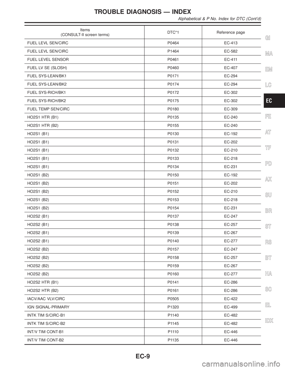
IACV/AAC VLV/CIRC P0505 EC-422
IGN SIGNAL-PRIMARY P1320 EC-499
INTK TIM S/CIRC-B1 P1140 EC-482
INTK TIM S/CIRC-B2 P1145 EC-482
INT/V TIM CONT-B1 P1110 EC-446
INT/V TIM CONT-B2 P1135 EC-446
GI
MA
EM
LC
FE
AT
TF
PD
AX
SU
BR
ST
RS
BT
HA
SC
EL
IDX
TROUBLE DIAGNOSIS Ð INDEX
Alphabetical & P No. Index for DTC (Cont'd)
EC-9
Page 547 of 2395

DTC*1Items
(CONSULT-II screen terms)Reference page
P0217 ENG OVER TEMP EC-314
P0300 MULTI CYL MISFIRE EC-320
P0301 CYL 1 MISFIRE EC-320
P0302 CYL 2 MISFIRE EC-320
P0303 CYL 3 MISFIRE EC-320
P0304 CYL 4 MISFIRE EC-320
P0305 CYL 5 MISFIRE EC-320
P0306 CYL 6 MISFIRE EC-320
P0325*2 KNOCK SEN/CIRC-B1 EC-328
P0335 CPS/CIRCUIT (POS) EC-334
P0340 CAM PS/CIRC (PHS) EC-342
P0420 TW CATALYST SYS-B1 EC-347
P0430 TW CATALYST SYS-B2 EC-347
P0440 EVAP SMALL LEAK EC-352
P0443 PURG VOLUME CONT/V EC-367
P0446 VENT CONTROL VALVE EC-374
P0450 EVAP SYS PRES SEN EC-381
P0455 EVAP GROSS LEAK EC-394
P0460 FUEL LV SE (SLOSH) EC-407
P0461 FUEL LEVEL SENSOR EC-411
P0464 FUEL LEVL SEN/CIRC EC-413
P0500 VEH SPEED SEN/CIRC*4 EC-417
P0505 IACV/AAC VLV/CIRC EC-422
P0510 CLOSED TP SW/CIRC EC-431
P0600*2 A/T COMM LINE EC-440
P0605 ECMEC-444
P0705 PNP SW/CIRC AT-111
P0710 ATF TEMP SEN/CIRC AT-116
P0720 VEH SPD SEN/CIR A/T*4 AT-124
P0725 ENGINE SPEED SIG AT-130
P0731 A/T 1ST GR FNCTN AT-136
P0732 A/T 2ND GR FNCTN AT-143
P0733 A/T 3RD GR FNCTN AT-151
P0734 A/T 4TH GR FNCTN AT-157
P0740 TCC SOLENOID/CIRC AT-165
P0744 A/T TCC S/V FNCTN AT-170
P0745 L/PRESS SOL/CIRC AT-174
TROUBLE DIAGNOSIS Ð INDEX
Alphabetical & P No. Index for DTC (Cont'd)
EC-12
Page 606 of 2395

Items
(CONSULT-II screen terms)DTC*1 SRT codeTest value/ Test
limit
(GST only)1st trip DTC*1 Reference page
KNOCK SEN/CIRC-B1 P0325 Ð Ð Ð EC-328
CPS/CIRCUIT (POS) P0335 Ð Ð X EC-334
CAM PS/CIRC (PHS) P0340 Ð Ð X EC-342
TW CATALYST SYS-B1 P0420 X X X*2 EC-347
TW CATALYST SYS-B2 P0430 X X X*2 EC-347
EVAP SMALL LEAK P0440 X X X*2 EC-352
PURG VOLUME CONT/V P0443 Ð Ð X EC-367
VENT CONTROL VALVE P0446 Ð Ð X EC-374
EVAP SYS PRES SEN P0450 Ð Ð X EC-381
EVAP GROSS LEAK P0455 X X X*2 EC-394
FUEL LV SE (SLOSH) P0460 Ð Ð X EC-407
FUEL LEVEL SENSOR P0461 Ð Ð X EC-411
FUEL LEVEL SEN/CIRC P0464 Ð Ð X EC-413
VEH SPEED SEN/CIRC P0500 Ð Ð X EC-417
IACV/AAC VLV/CIRC P0505 Ð Ð X EC-422
CLOSED TP SW/CIRC P0510 Ð Ð X EC-431
A/T COMM LINE P0600 Ð Ð Ð EC-440
ECM P0605 Ð Ð X EC-444
PNP SW/CIRC P0705 Ð Ð X AT-111
ATF TEMP SEN/CIRC P0710 Ð Ð X AT-116
VEH SPD SEN/CIR AT P0720 Ð Ð X AT-124
ENGINE SPEED SIG P0725 Ð Ð X AT-130
A/T 1ST GR FNCTN P0731 Ð Ð X AT-136
A/T 2ND GR FNCTN P0732 Ð Ð X AT-143
A/T 3RD GR FNCTN P0733 Ð Ð X AT-151
A/T 4TH GR FNCTN P0734 Ð Ð X AT-157
TCC SOLENOID/CIRC P0740 Ð Ð X AT-165
A/T TCC S/V FNCTN P0744 Ð Ð X AT-170
L/PRESS SOL/CIRC P0745 Ð Ð X AT-174
SFT SOL A/CIRC P0750 Ð Ð X AT-180
SFT SOL B/CIRC P0755 Ð Ð X AT-189
INT/V TIM CONT-B1 P1110 Ð Ð X EC-446
INT/V TIM V/CIR-B1 P1111 Ð Ð XEC-451
SWIRL CONT SOL/V P1130 Ð Ð X EC-458
INT/V TIM CONT-B2 P1135 Ð Ð X EC-446
INT/V TIM V/CIR-B2 P1136 Ð Ð X EC-451
INTK TIM S/CIRC-B1 P1140 Ð Ð X EC-482
GI
MA
EM
LC
FE
AT
TF
PD
AX
SU
BR
ST
RS
BT
HA
SC
EL
IDX
ON BOARD DIAGNOSTIC SYSTEM DESCRIPTION
Emission-related Diagnostic Information (Cont'd)
EC-71
Page 651 of 2395
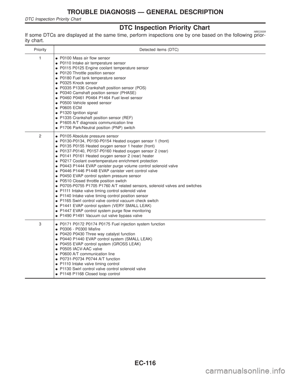
DTC Inspection Priority ChartNBEC0039If some DTCs are displayed at the same time, perform inspections one by one based on the following prior-
ity chart.
Priority Detected items (DTC)
1IP0100 Mass air flow sensor
IP0110 Intake air temperature sensor
IP0115 P0125 Engine coolant temperature sensor
IP0120 Throttle position sensor
IP0180 Fuel tank temperature sensor
IP0325 Knock sensor
IP0335 P1336 Crankshaft position sensor (POS)
IP0340 Camshaft position sensor (PHASE)
IP0460 P0461 P0464 P1464 Fuel level sensor
IP0500 Vehicle speed sensor
IP0605 ECM
IP1320 Ignition signal
IP1335 Crankshaft position sensor (REF)
IP1605 A/T diagnosis communication line
IP1706 Park/Neutral position (PNP) switch
2IP0105 Absolute pressure sensor
IP0130-P0134, P0150-P0154 Heated oxygen sensor 1 (front)
IP0135 P0155 Heated oxygen sensor 1 heater (front)
IP0137-P0140, P0157-P0160 Heated oxygen sensor 2 (rear)
IP0141 P0161 Heated oxygen sensor 2 (rear) heater
IP0217 Coolant overtemperature enrichment protection
IP0443 P1444 EVAP canister purge volume control solenoid valve
IP0446 P1446 P1448 EVAP canister vent control valve
IP0450 EVAP control system pressure sensor
IP0510 Closed throttle position switch
IP0705-P0755 P1705 P1760 A/T related sensors, solenoid valves and switches
IP 1111Intake valve timing control solenoid valve
IP1140 Intake valve timing control position sensor
IP1165 Swirl control valve control vacuum check switch
IP1441 EVAP control system (VERY SMALL LEAK)
IP1447 EVAP control system purge flow monitoring
IP1490 P1491 Vacuum cut valve bypass valve
3IP0171 P0172 P0174 P0175 Fuel injection system function
IP0306 - P0300 Misfire
IP0420 P0430 Three way catalyst function
IP0440 P1440 EVAP control system (SMALL LEAK)
IP0455 EVAP control system (GROSS LEAK)
IP0505 IACV-AAC valve
IP0600 A/T communication line
IP0731-P0734 P0744 A/T function
IP1110 Intake valve timing control
IP1130 Swirl control valve control solenoid valve
IP1148 P1168 Closed loop control
TROUBLE DIAGNOSIS Ð GENERAL DESCRIPTION
DTC Inspection Priority Chart
EC-116
Page 957 of 2395

DescriptionNBEC0249SYSTEM DESCRIPTIONNBEC0249S01
Sensor Input Signal to ECMECM func-
tionActuator
Crankshaft position sensor (POS) Engine speed (POS signal)
Idle air
controlIACV-AAC valve Crankshaft position sensor (REF) Engine speed (REF signal)
Mass air flow sensor Amount of intake air
Engine coolant temperature sensor Engine coolant temperature
Ignition switch Start signal
Throttle position sensor Throttle position
Park/neutral position (PNP) switch Park/neutral position
Air conditioner switch Air conditioner operation
Power steering oil pressure switch Power steering load signal
Battery Battery voltage
Vehicle speed sensor Vehicle speed
Ambient air temperature switch Ambient air temperature
Intake air temperature sensor Intake air temperature
Absolute pressure sensor Ambient barometic pressure
This system automatically controls engine idle speed to a specified
level. Idle speed is controlled through fine adjustment of the
amount of air which by-passes the throttle valve via IACV-AAC
valve. The IACV-AAC valve changes the opening of the air by-pass
passage to control the amount of auxiliary air. This valve is actu-
ated by a step motor built into the valve, which moves the valve in
the axial direction in steps corresponding to the ECM output sig-
nals. One step of IACV-AAC valve movement causes the respec-
tive opening of the air by-pass passage. (i.e. when the step
advances, the opening is enlarged.) The opening of the valve is
varied to allow for optimum control of the engine idling speed. The
crankshaft position sensor (POS) detects the actual engine speed
and sends a signal to the ECM. The ECM then controls the step
position of the IACV-AAC valve so that engine speed coincides with
the target value memorized in ECM. The target engine speed is the
lowest speed at which the engine can operate steadily. The opti-
mum value stored in the ECM is determined by takig into consid-
eration various engine conditions, such as during warm up,
deceleration, and engine load (air conditioner, power steering and
cooling fan operation).
SEF765P
COMPONENT DESCRIPTIONNBEC0249S02IACV-AAC ValveNBEC0249S0201The IACV-AAC valve is operated by a step motor for centralized
control of auxiliary air supply. This motor has four winding phases
and is actuated by the output signals of ECM which turns ON and
OFF two windings each in seqeunce. Each time the IACV-AAC
valve opens or closes to change tha auxiliary air quantity, the ECM
sends a pulse signal to the step motor. When no change in the
auxiliary air quantity is needed, the ECM does not issue the pulse
signal. A certain voltage signal is issued so that the valve remains
at that particular opening.
DTC P0505 IDLE AIR CONTROL VALVE (IACV) Ð AUXILIARY AIR CONTROL
(AAC) VALVE
Description
EC-422
Page 958 of 2395
CONSULT-II Reference Value in Data Monitor
Mode
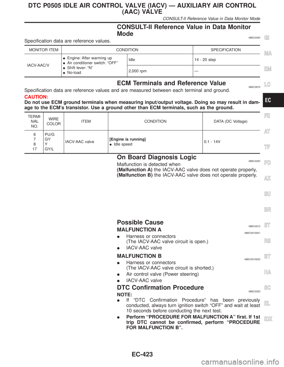
NBEC0250Specification data are reference values.
MONITOR ITEM CONDITION SPECIFICATION
IACV-AAC/VIEngine: After warming up
IAir conditioner switch: ªOFFº
IShift lever: ªNº
INo-loadIdle 14 - 20 step
2,000 rpm Ð
ECM Terminals and Reference ValueNBEC0670Specification data are reference values and are measured between each terminal and ground.
CAUTION:
Do not use ECM ground terminals when measuring input/output voltage. Doing so may result in dam-
age to the ECM's transistor. Use a ground other than ECM terminals, such as the ground.
TERMI-
NAL
NO.WIRE
COLORITEM CONDITION DATA (DC Voltage)
6
7
8
17PU/G
GY
Y
GY/LIACV-AAC valve[Engine is running]
IIdle speed0.1 - 14V
On Board Diagnosis LogicNBEC0252Malfunction is detected when
(Malfunction A)the IACV-AAC valve does not operate properly,
(Malfunction B)the IACV-AAC valve does not operate properly.
Possible CauseNBEC0515MALFUNCTION ANBEC0515S01IHarness or connectors
(The IACV-AAC valve circuit is open.)
IIACV-AAC valve
MALFUNCTION BNBEC0515S02IHarness or connectors
(The IACV-AAC valve circuit is shorted.)
IAir control valve (Power steering)
IIACV-AAC valve
DTC Confirmation ProcedureNBEC0253NOTE:
IIf ªDTC Confirmation Procedureº has been previously
conducted, always turn ignition switch ªOFFº and wait at least
10 seconds before conducting the next test.
IPerform ªPROCEDURE FOR MALFUNCTION Aº first. If 1st
trip DTC cannot be confirmed, perform ªPROCEDURE
FOR MALFUNCTION Bº.
GI
MA
EM
LC
FE
AT
TF
PD
AX
SU
BR
ST
RS
BT
HA
SC
EL
IDX
DTC P0505 IDLE AIR CONTROL VALVE (IACV) Ð AUXILIARY AIR CONTROL
(AAC) VALVE
CONSULT-II Reference Value in Data Monitor Mode
EC-423
Page 959 of 2395

SEF058Y
PROCEDURE FOR MALFUNCTION ANBEC0253S01TESTING CONDITION:
Before performing the following procedure, confirm that bat-
tery voltage is more than 10.5V with ignition switch ªONº.
With CONSULT-IINBEC0253S01011) Start engine and warm it up to normal operating temperature.
2) Turn ignition switch ªOFFº and wait at least 10 seconds.
3) Perform ªIdle Air Volume Learningº (see EC-57).
4) Turn ignition switch ªOFFº and wait at least 10 seconds.
5) Turn ignition switch ªONº.
6) Select ªDATA MONITORº mode with CONSULT-II.
7) Start engine and let it idle.
8) Keep engine speed at 2,500 rpm for three seconds, then let it
idle for three seconds.
Do not rev engine to more than 3,000 rpm.
9) Perform step 4 once more.
10) If 1st trip DTC is detected, go to ªDiagnostic Procedureº,
EC-426.
With GSTNBEC0253S0102Follow the procedure ªWith CONSULT-IIº above.
SEF174Y
PROCEDURE FOR MALFUNCTION BNBEC0253S02TESTING CONDITION:
IBefore performing the following procedure, confirm that
battery voltage is more than 11V at idle.
IAlways perform the test at a temperature above þ10ÉC
(14ÉF).
With CONSULT-IINBEC0253S02011) Open engine hood.
2) Start engine and warm it up to normal operating temperature.
3) Turn ignition switch ªOFFº and wait at least 10 seconds.
4) Perform ªIdle Air Volume Learningº (see EC-57).
5) Turn ignition switch ªOFFº and wait at least 10 seconds.
6) Turn ignition switch ªONº again and select ªDATA MONITORº
mode with CONSULT-II
7) Start engine and run it for at least 1 minute at idle speed.
8) If 1st trip DTC is detected, go to ªDiagnostic Procedureº,
EC-426.
With GSTNBEC0253S0202Follow the procedure ªWith CONSULT-IIº above.
DTC P0505 IDLE AIR CONTROL VALVE (IACV) Ð AUXILIARY AIR CONTROL
(AAC) VALVE
DTC Confirmation Procedure (Cont'd)
EC-424
Page 960 of 2395

Wiring DiagramNBEC0254
MEC966C
GI
MA
EM
LC
FE
AT
TF
PD
AX
SU
BR
ST
RS
BT
HA
SC
EL
IDX
DTC P0505 IDLE AIR CONTROL VALVE (IACV) Ð AUXILIARY AIR CONTROL
(AAC) VALVE
Wiring Diagram
EC-425
Page 961 of 2395
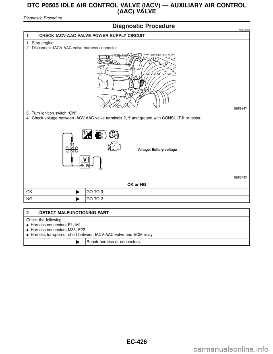
Diagnostic ProcedureNBEC0255
1 CHECK IACV-AAC VALVE POWER SUPPLY CIRCUIT
1. Stop engine.
2. Disconnect IACV-AAC valve harness connector.
SEF994Y
3. Turn ignition switch ªONº.
4. Check voltage between IACV-AAC valve terminals 2, 5 and ground with CONSULT-II or tester.
SEF343X
OK or NG
OK©GO TO 3.
NG©GO TO 2.
2 DETECT MALFUNCTIONING PART
Check the following.
IHarness connectors E1, M1
IHarness connectors M33, F22
IHarness for open or short between IACV-AAC valve and ECM relay
©Repair harness or connectors.
DTC P0505 IDLE AIR CONTROL VALVE (IACV) Ð AUXILIARY AIR CONTROL
(AAC) VALVE
Diagnostic Procedure
EC-426