check transmission fluid INFINITI QX4 2001 Factory Service Manual
[x] Cancel search | Manufacturer: INFINITI, Model Year: 2001, Model line: QX4, Model: INFINITI QX4 2001Pages: 2395, PDF Size: 43.2 MB
Page 6 of 2395

AUTOMATIC TRANSMISSION
SECTION
AT
CONTENTS
TROUBLE DIAGNOSIS - INDEX....................................4
Alphabetical & P No. Index for DTC ...........................4
PRECAUTIONS...............................................................6
Precautions for Supplemental Restraint System
(SRS)²AIR BAG²and²SEAT BELT
PRE-TENSIONER²......................................................6
Precautions for On Board Diagnostic (OBD)
System of A/T and Engine...........................................6
Precautions ..................................................................6
Service Notice or Precautions .....................................8
Wiring Diagrams and Trouble Diagnosis .....................9
PREPARATION.............................................................10
Special Service Tools ................................................10
OVERALL SYSTEM......................................................12
A/T Electrical Parts Location .....................................12
Circuit Diagram ..........................................................13
Cross-sectional View .................................................14
Hydraulic Control Circuit ............................................15
Shift Mechanism ........................................................16
Control System ..........................................................25
Control Mechanism ....................................................26
Control Valve .............................................................31
ON BOARD DIAGNOSTIC SYSTEM
DESCRIPTION...............................................................33
Introduction ................................................................33
OBD-II Function for A/T System ................................33
One or Two Trip Detection Logic of OBD-II ..............33
OBD-II Diagnostic Trouble Code (DTC) ....................33
Malfunction Indicator Lamp (MIL) ..............................37
CONSULT-II ...............................................................37
Diagnostic Procedure Without CONSULT-II ..............46
TROUBLE DIAGNOSIS - INTRODUCTION..................53
Introduction ................................................................53
Work Flow ..................................................................57
TROUBLE DIAGNOSIS - BASIC INSPECTION...........59
A/T Fluid Check .........................................................59
Stall Test ....................................................................59
Line Pressure Test .....................................................62
Road Test...................................................................63TROUBLE DIAGNOSIS - GENERAL
DESCRIPTION...............................................................81
Symptom Chart ..........................................................81
TCM Terminals and Reference Value........................92
TROUBLE DIAGNOSIS FOR POWER SUPPLY..........96
Wiring Diagram - AT - MAIN ......................................96
Diagnostic Procedure ................................................97
DTC P0705 PARK/NEUTRAL POSITION SWITCH.....99
Description .................................................................99
Wiring Diagram - AT - PNP/SW...............................101
Diagnostic Procedure ..............................................102
Component Inspection .............................................103
DTC P0710 A/T FLUID TEMPERATURE SENSOR
CIRCUIT.......................................................................105
Description ...............................................................105
Wiring Diagram - AT - FTS ......................................107
Diagnostic Procedure ..............................................108
Component Inspection ............................................. 110
DTC P0720 VEHICLE SPEED SENSOR.A/T
(REVOLUTION SENSOR)........................................... 111
Description ............................................................... 111
Wiring Diagram - AT - VSSA/T ................................ 113
Diagnostic Procedure .............................................. 114
Component Inspection ............................................. 115
DTC P0725 ENGINE SPEED SIGNAL....................... 116
Description ............................................................... 116
Wiring Diagram - AT - ENGSS ................................ 117
Diagnostic Procedure .............................................. 118
DTC P0731 IMPROPER SHIFTING TO 1ST GEAR
POSITION....................................................................120
Description ...............................................................120
Wiring Diagram - AT - 1ST ......................................123
Diagnostic Procedure ..............................................124
Component Inspection .............................................125
DTC P0732 IMPROPER SHIFTING TO 2ND GEAR
POSITION....................................................................126
Description ...............................................................126
Wiring Diagram - AT - 2ND......................................129
Diagnostic Procedure ..............................................130
GI
MA
EM
LC
EC
FE
TF
PD
AX
SU
BR
ST
RS
BT
HA
SC
EL
IDX
Page 13 of 2395

IBefore assembly, apply a coat of recommended ATF to all
parts. Apply petroleum jelly to protect O-rings and seals, or
hold bearings and washers in place during assembly. Do not
use grease.
IExtreme care should be taken to avoid damage to O-rings,
seals and gaskets when assembling.
IReplace ATF cooler if excessive foreign material is found in oil
pan or clogging strainer. Refer to ªATF COOLER SERVICEº,
AT-9.
IAfter overhaul, refill the transmission with new ATF.
IWhen the A/T drain plug is removed, only some of the fluid is
drained. Old A/T fluid will remain in torque converter and ATF
cooling system.
Always follow the procedures when changing A/T fluid. Refer
to MA-21, ªChanging A/T Fluidº.
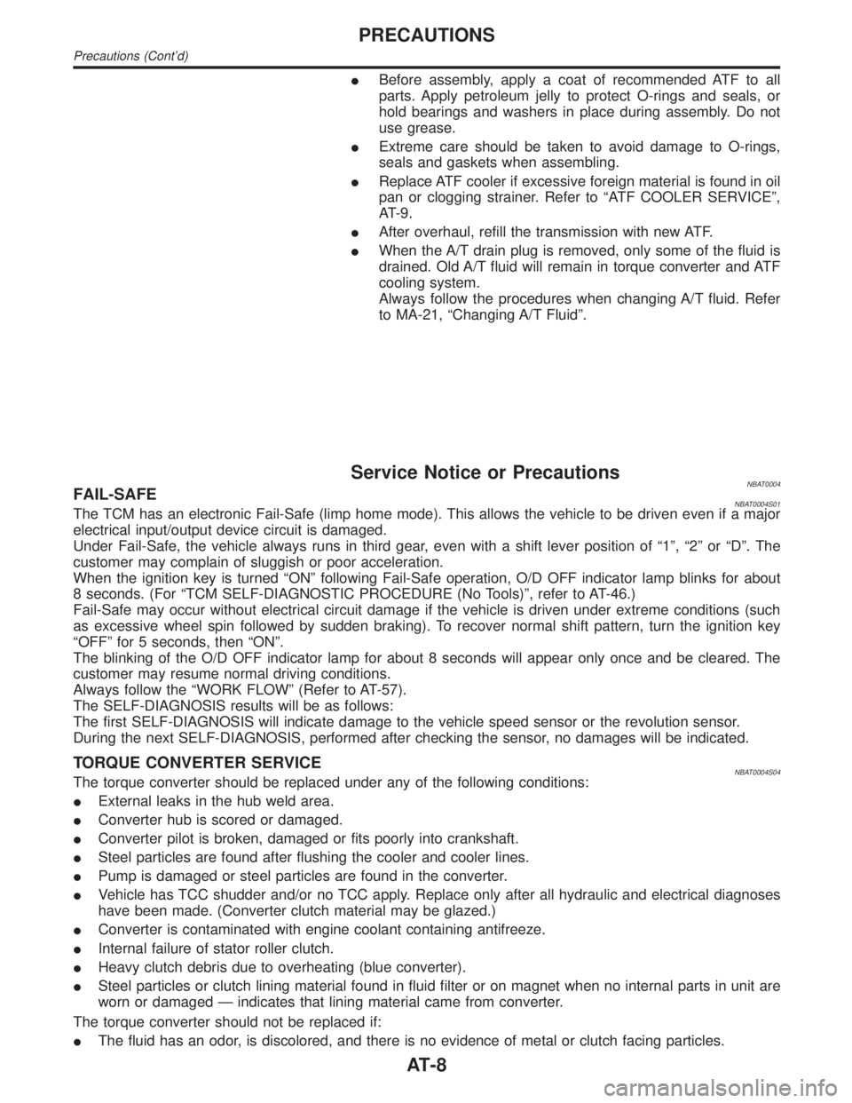
Service Notice or PrecautionsNBAT0004FAIL-SAFENBAT0004S01The TCM has an electronic Fail-Safe (limp home mode). This allows the vehicle to be driven even if a major
electrical input/output device circuit is damaged.
Under Fail-Safe, the vehicle always runs in third gear, even with a shift lever position of ª1º, ª2º or ªDº. The
customer may complain of sluggish or poor acceleration.
When the ignition key is turned ªONº following Fail-Safe operation, O/D OFF indicator lamp blinks for about
8 seconds. (For ªTCM SELF-DIAGNOSTIC PROCEDURE (No Tools)º, refer to AT-46.)
Fail-Safe may occur without electrical circuit damage if the vehicle is driven under extreme conditions (such
as excessive wheel spin followed by sudden braking). To recover normal shift pattern, turn the ignition key
ªOFFº for 5 seconds, then ªONº.
The blinking of the O/D OFF indicator lamp for about 8 seconds will appear only once and be cleared. The
customer may resume normal driving conditions.
Always follow the ªWORK FLOWº (Refer to AT-57).
The SELF-DIAGNOSIS results will be as follows:
The first SELF-DIAGNOSIS will indicate damage to the vehicle speed sensor or the revolution sensor.
During the next SELF-DIAGNOSIS, performed after checking the sensor, no damages will be indicated.
TORQUE CONVERTER SERVICENBAT0004S04The torque converter should be replaced under any of the following conditions:
IExternal leaks in the hub weld area.
IConverter hub is scored or damaged.
IConverter pilot is broken, damaged or fits poorly into crankshaft.
ISteel particles are found after flushing the cooler and cooler lines.
IPump is damaged or steel particles are found in the converter.
IVehicle has TCC shudder and/or no TCC apply. Replace only after all hydraulic and electrical diagnoses
have been made. (Converter clutch material may be glazed.)
IConverter is contaminated with engine coolant containing antifreeze.
IInternal failure of stator roller clutch.
IHeavy clutch debris due to overheating (blue converter).
ISteel particles or clutch lining material found in fluid filter or on magnet when no internal parts in unit are
worn or damaged Ð indicates that lining material came from converter.
The torque converter should not be replaced if:
IThe fluid has an odor, is discolored, and there is no evidence of metal or clutch facing particles.
PRECAUTIONS
Precautions (Cont'd)
AT-8
Page 64 of 2395

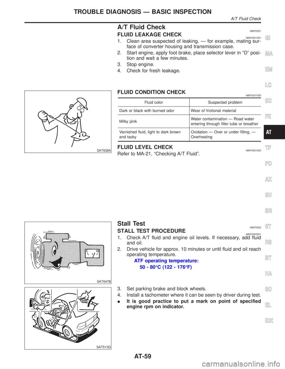
A/T Fluid CheckNBAT0021FLUID LEAKAGE CHECKNBAT0021S011. Clean area suspected of leaking. Ð for example, mating sur-
face of converter housing and transmission case.
2. Start engine, apply foot brake, place selector lever in ªDº posi-
tion and wait a few minutes.
3. Stop engine.
4. Check for fresh leakage.
SAT638A
FLUID CONDITION CHECKNBAT0021S02
Fluid color Suspected problem
Dark or black with burned odor Wear of frictional material
Milky pinkWater contamination Ð Road water
entering through filler tube or breather
Varnished fluid, light to dark brown
and tackyOxidation Ð Over or under filling, Ð
Overheating
FLUID LEVEL CHECKNBAT0021S03Refer to MA-21, ªChecking A/T Fluidº.
SAT647B
Stall TestNBAT0022STALL TEST PROCEDURENBAT0022S011. Check A/T fluid and engine oil levels. If necessary, add fluid
and oil.
2. Drive vehicle for approx. 10 minutes or until fluid and oil reach
operating temperature.
ATF operating temperature:
50 - 80ÉC (122 - 176ÉF)
SAT513G
3. Set parking brake and block wheels.
4. Install a tachometer where it can be seen by driver during test.
IIt is good practice to put a mark on point of specified
engine rpm on indicator.
GI
MA
EM
LC
EC
FE
TF
PD
AX
SU
BR
ST
RS
BT
HA
SC
EL
IDX
TROUBLE DIAGNOSIS Ð BASIC INSPECTION
A/T Fluid Check
AT-59
Page 126 of 2395

SAT014K
SAT971J
SAT021J
DIAGNOSTIC TROUBLE CODE (DTC) CONFIRMATION
PROCEDURE
NBAT0039S01CAUTION:
IAlways drive vehicle at a safe speed.
IBe careful not to rev engine into the red zone on the
tachometer.
NOTE:
If ªDIAGNOSTIC TROUBLE CODE CONFIRMATION PROCE-
DUREº has been previously conducted, always turn ignition
switch ªOFFº and wait at least 5 seconds before conducting
the next test.
TESTING CONDITIONS:
Always drive vehicle on a level road to improve the accuracy of
test.
After the repair, perform the following procedure to confirm the
malfunction is eliminated.
With CONSULT-II
1) Start engine and select ªDATA MONITORº mode for ªA/Tº with
CONSULT-II.
2) Make sure that output voltage of A/T fluid temperature sensor
is within the range below.
FLUID TEMP SEN: 0.4 - 1.5V
If out of range, drive the vehicle to decrease the voltage (warm
up the fluid) or stop engine to increase the voltage (cool down
the fluid).
3) Select ª1ST GR FNCTN P0731º of ªDTC WORK SUPPORTº
mode for ªA/Tº with CONSULT-II and touch ªSTARTº.
4) Accelerate vehicle to 10 to 20 km/h (6 to 12 MPH) under the
following condition and release the accelerator pedal com-
pletely.
THROTTLE POSI: Less than 1.0/8 (at all times during step
4)
Selector lever: D position (OD ªONº)
ICheck that ªGEARº shows ª2º after releasing pedal.
5) Depress accelerator pedal to WOT (more than 7.0/8 of
ªTHROTTLE POSIº) quickly from a speed of 10 to 20 km/h (6
to 12 MPH) until ªTESTINGº changes to ªSTOP VEHICLEº or
ªCOMPLETEDº. (It will take approximately 3 seconds.)
If the check result NG appears on CONSULT-II screen, go to
ªDIAGNOSTIC PROCEDUREº, AT-124.
If ªSTOP VEHICLEº appears on CONSULT-II screen, go to the
following step.
ICheck that ªGEARº shows ª1º when depressing accelera-
tor pedal to WOT.
IIf ªTESTINGº does not appear on CONSULT-II for a long
time, select ªSELF-DIAG RESULTSº for ªENGINEº. In case
a 1st trip DTC other than P0731 is shown, refer to appli-
cable ªTROUBLE DIAGNOSIS FOR DTCº.
6) Stop vehicle.
7) Follow the instruction displayed. (Check for normal shifting
referring to the table below.)
Vehicle conditionGear on actual transmission shift pattern when
screen is changed to 1,2,3,4
No malfunction exists 1,2,3,4
GI
MA
EM
LC
EC
FE
TF
PD
AX
SU
BR
ST
RS
BT
HA
SC
EL
IDX
DTC P0731 IMPROPER SHIFTING TO 1ST GEAR POSITION
Description (Cont'd)
AT-121
Page 132 of 2395

SAT014K
SAT971J
SAT021J
DIAGNOSTIC TROUBLE CODE (DTC) CONFIRMATION
PROCEDURE
NBAT0042S01CAUTION:
IAlways drive vehicle at a safe speed.
IBe careful not to rev engine into the red zone on the
tachometer.
NOTE:
If ªDIAGNOSTIC TROUBLE CODE CONFIRMATION PROCE-
DUREº has been previously conducted, always turn ignition
switch ªOFFº and wait at least 5 seconds before conducting
the next test.
TESTING CONDITIONS:
Always drive vehicle on a level road to improve the accuracy
of test.
After the repair, perform the following procedure to confirm the
malfunction is eliminated.
With CONSULT-II
1) Start engine and select ªDATA MONITORº mode for ªA/Tº with
CONSULT-II.
2) Make sure that output voltage of A/T fluid temperature sensor
is within the range below.
FLUID TEMP SEN: 0.4 - 1.5V
If out of range, drive the vehicle to decrease the voltage (warm
up the fluid) or stop engine to increase the voltage (cool down
the fluid).
3) Select ª2ND GR FNCTN P0732º of ªDTC WORK SUPPORTº
mode for ªA/Tº with CONSULT-II and touch ªSTARTº.
4) Accelerate vehicle to 25 to 30 km/h (16 to 19 MPH) under the
following condition and release the accelerator pedal com-
pletely.
THROTTLE POSI: Less than 1.0/8 (at all times during step
4)
Selector lever: D position (OD ªONº)
ICheck that ªGEARº shows ª3º or ª4º after releasing pedal.
5) Depress accelerator pedal to WOT (more than 7.0/8 of
ªTHROTTLE POSIº) quickly from a speed of 25 to 30 km/h (16
to 19 MPH) until ªTESTINGº changes to ªSTOP VEHICLEº or
ªCOMPLETEDº. (It will take approximately 3 seconds.)
If the check result NG appears on CONSULT-II screen, go to
ªDIAGNOSTIC PROCEDUREº, AT-130.
If ªSTOP VEHICLEº appears on CONSULT-II screen, go to
following step.
ICheck that ªGEARº shows ª2º when depressing accelera-
tor pedal to WOT.
IIf ªTESTINGº does not appear on CONSULT-II for a long
time, select ªSELF-DIAG RESULTSº for ªENGINEº. In case
a 1st trip DTC other than P0732 is shown, refer to appli-
cable ªTROUBLE DIAGNOSIS FOR DTCº.
6) Stop vehicle.
7) Follow the instruction displayed. (Check for normal shifting
referring to the table below.)
Vehicle conditionGear on actual transmission shift pattern when
screen is changed to 1,2,3,4
No malfunction exists 1,2,3,4
Malfunction for P0732 exists. 4,3,3,4
GI
MA
EM
LC
EC
FE
TF
PD
AX
SU
BR
ST
RS
BT
HA
SC
EL
IDX
DTC P0732 IMPROPER SHIFTING TO 2ND GEAR POSITION
Description (Cont'd)
AT-127
Page 138 of 2395

SAT014K
SAT971J
SAT021J
DIAGNOSTIC TROUBLE CODE (DTC) CONFIRMATION
PROCEDURE
NBAT0045S01CAUTION:
IAlways drive vehicle at a safe speed.
IBe careful not to rev engine into the red zone on the
tachometer.
NOTE:
If ªDIAGNOSTIC TROUBLE CODE CONFIRMATION PROCE-
DUREº has been previously conducted, always turn ignition
switch ªOFFº and wait at least 5 seconds before conducting
the next test.
TESTING CONDITIONS:
Always drive vehicle on a level road to improve the accuracy
of test.
After the repair, perform the following procedure to confirm the
malfunction is eliminated.
With CONSULT-II
1) Start engine and select ªDATA MONITORº mode for ªA/Tº with
CONSULT-II.
2) Make sure that output voltage of A/T fluid temperature sensor
is within the range below.
FLUID TEMP SEN: 0.4 - 1.5V
If out of range, drive the vehicle to decrease the voltage (warm
up the fluid) or stop engine to increase the voltage (cool down
the fluid).
3) Select ª3RD GR FNCTN P0733º of ªDTC WORK SUPPORTº
mode for ªA/Tº with CONSULT-II and touch ªSTARTº.
4) Accelerate vehicle to 35 to 45 km/h (22 to 28 MPH) under the
following condition and release the accelerator pedal com-
pletely.
THROTTLE POSI: Less than 1.0/8 (at all times during step
4)
Selector lever: D position (OD ªONº)
ICheck that ªGEARº shows ª4º after releasing pedal.
5) Depress accelerator pedal steadily with 3.5/8 - 4.5/8 of
ªTHROTTLE POSIº from a speed of 35 to 45 km/h (22 to 28
MPH) until ªTESTINGº changes to ªSTOP VEHICLEº or ªCOM-
PLETEDº. (It will take approximately 3 seconds.)
If the check result NG appears on CONSULT-II screen, go to
ªDIAGNOSTIC PROCEDUREº, AT-136.
If ªSTOP VEHICLEº appears on CONSULT-II screen, go to
following step.
ICheck that ªGEARº shows ª3º when depressing accelera-
tor pedal with 3.5/8 - 4.5/8 of ªTHROTTLE POSIº.
IIf ªTESTINGº does not appear on CONSULT-II for a long
time, select ªSELF-DIAG RESULTSº for ªENGINEº. In case
a 1st trip DTC other than P0733 is shown, refer to appli-
cable ªTROUBLE DIAGNOSIS FOR DTCº.
6) Stop vehicle.
7) Follow the instruction displayed. (Check for normal shifting
referring to the table below.)
Vehicle conditionGear on actual transmission shift pattern
when screen is changed to 1,2,3,4
No malfunction exists. 1,2,3,4
Malfunction for P0733 exists. 1,1,4,4
GI
MA
EM
LC
EC
FE
TF
PD
AX
SU
BR
ST
RS
BT
HA
SC
EL
IDX
DTC P0733 IMPROPER SHIFTING TO 3RD GEAR POSITION
Description (Cont'd)
AT-133
Page 145 of 2395

SAT014K
SAT971J
SAT021J
DIAGNOSTIC TROUBLE CODE (DTC) CONFIRMATION
PROCEDURE
NBAT0048S01CAUTION:
IAlways drive vehicle at a safe speed.
IBe careful not to rev engine into the red zone on the
tachometer.
NOTE:
If ªDIAGNOSTIC TROUBLE CODE CONFIRMATION PROCE-
DUREº has been previously conducted, always turn ignition
switch ªOFFº and wait at least 5 seconds before conducting
the next test.
TESTING CONDITIONS:
Always drive vehicle on a level road to improve the accuracy
of test.
After the repair, perform the following procedure to confirm the
malfunction is eliminated.
With CONSULT-II
1) Start engine and select ªDATA MONITORº mode for ªA/Tº with
CONSULT-II.
2) Make sure that output voltage of A/T fluid temperature sensor
is within the range below.
FLUID TEMP SEN: 0.4 - 1.5V
If out of range, drive the vehicle to decrease the voltage (warm
up the fluid) or stop engine to increase the voltage (cool down
the fluid).
3) Select ª4TH GR FNCTN P0734º of ªDTC WORK SUPPORTº
mode for ªA/Tº with CONSULT-II and touch ªSTARTº.
4) Accelerate vehicle to 55 to 65 km/h (34 to 40 MPH) under the
following condition and release the accelerator pedal com-
pletely.
THROTTLE POSI: Less than 5.5/8 (at all times during step
4)
Selector lever: D position (OD ªONº)
ICheck that ªGEARº shows ª3º after releasing pedal.
5) Depress accelerator pedal steadily with 1.0/8 - 2.0/8 of
ªTHROTTLE POSIº from a speed of 55 to 65 km/h (34 to 40
MPH) until ªTESTINGº has turned to ªSTOP VEHICLEº or
ªCOMPLETEDº. (It will take approximately 3 seconds.)
If the check result NG appears on CONSULT-II screen, go to
ªDIAGNOSTIC PROCEDUREº, AT-143.
If ªSTOP VEHICLEº appears on CONSULT-II screen, go to
following step.
ICheck that ªGEARº shows ª4º when depressing accelera-
tor pedal with 1.0/8 - 2.0/8 of ªTHROTTLE POSIº.
IIf ªTESTINGº does not appear on CONSULT-II for a long
time, select ªSELF-DIAG RESULTSº for ªENGINEº. In case
a 1st trip DTC other than P0734 is shown, refer to appli-
cable ªTROUBLE DIAGNOSIS FOR DTCº.
6) Stop vehicle.
7) Follow the instruction displayed. (Check for normal shifting
referring to the table below.)
Vehicle conditionGear on actual transmission shift pattern when
screen is changed to 1,2,3,4
No malfunction exists 1,2,3,4
Malfunction for P0734 exists. 1,2,2,1
DTC P0734 IMPROPER SHIFTING TO 4TH GEAR POSITION
Description (Cont'd)
AT-140
Page 284 of 2395

SAT017B
IWhen connecting torque converter to transmission, measure
distance ªAº to be certain that they are correctly assembled.
Distance ªAº:
25.0 mm (0.984 in) or more
SAT148K
IInstall converter to drive plate.
IAfter converter is installed to drive plate, rotate crankshaft
several turns and check to be sure that transmission
rotates freely without binding.
SAT149K
ITighten bolts securing transmission.
Bolt No.Tightening torque
N´m (kg-m, ft-lb)Bolt length ªº
mm (in)
1 70 - 80 (7.1 - 8.2, 52 - 59) 65 (2.56)
2 70 - 80 (7.1 - 8.2, 52 - 59) 55 (2.17)
3 29 - 39 (3.0 - 4.0, 22 - 29) 40 (1.57)
IReinstall any part removed.
SAT638A
ICheck fluid level in transmission.
IMove selector lever through all positions to be sure that trans-
mission operates correctly.
With parking brake applied, rotate engine at idling. Move selec-
tor lever through ªNº to ªDº, to ª2º, to ª1º and to ªRº positions.
A slight shock should be felt by hand gripping selector each
time transmission is shifted.
IPerform road test. Refer to ªROAD TESTº, AT-63.
GI
MA
EM
LC
EC
FE
TF
PD
AX
SU
BR
ST
RS
BT
HA
SC
EL
IDX
REMOVAL AND INSTALLATION
Installation (Cont'd)
AT-279
Page 359 of 2395

SAT010B
j. Install torque converter clutch solenoid valve and A/T fluid tem-
perature sensor connectors.
SAT011B
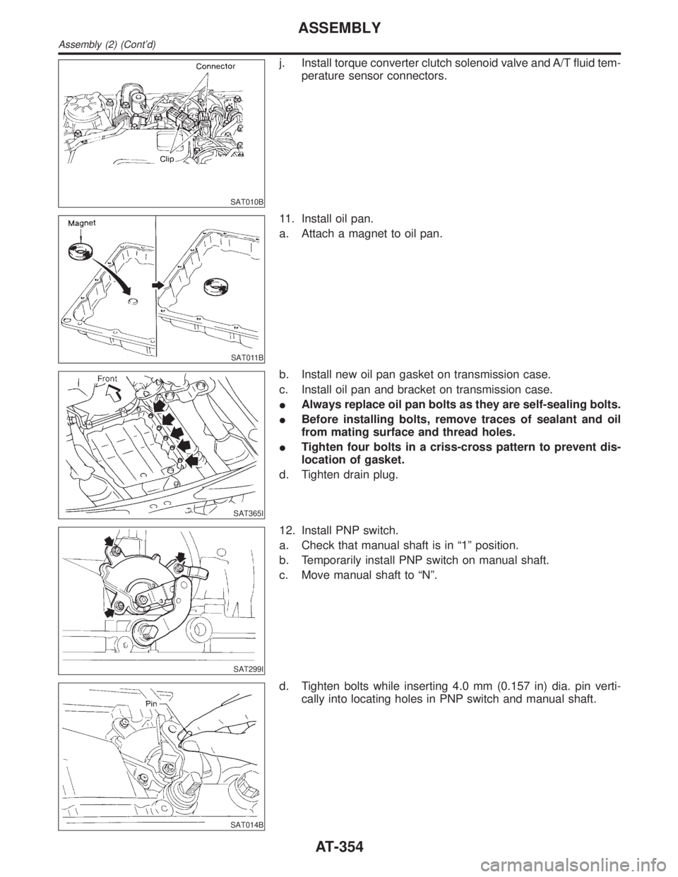
11. Install oil pan.
a. Attach a magnet to oil pan.
SAT365I
b. Install new oil pan gasket on transmission case.
c. Install oil pan and bracket on transmission case.
IAlways replace oil pan bolts as they are self-sealing bolts.
IBefore installing bolts, remove traces of sealant and oil
from mating surface and thread holes.
ITighten four bolts in a criss-cross pattern to prevent dis-
location of gasket.
d. Tighten drain plug.
SAT299I
12. Install PNP switch.
a. Check that manual shaft is in ª1º position.
b. Temporarily install PNP switch on manual shaft.
c. Move manual shaft to ªNº.
SAT014B
d. Tighten bolts while inserting 4.0 mm (0.157 in) dia. pin verti-
cally into locating holes in PNP switch and manual shaft.
ASSEMBLY
Assembly (2) (Cont'd)
AT-354
Page 592 of 2395

SEF452Y
Idle Air Volume LearningNBEC0642
SEF454Y
SEF455Y
DESCRIPTIONNBEC0642S01ªIdle Air Volume Learningº is an operation to learn the idle air vol-
ume that keeps each engine within the specific range. It must be
performed under any of the following conditions:
IEach time IACV-AAC valve, throttle body or ECM is replaced.
IIdle speed or ignition timing is out of specification.
PRE-CONDITIONINGNBEC0642S02Before performing ªIdle Air Volume Learningº, make sure that all of
the following conditions are satisfied.
Learning will be cancelled if any of the following conditions are
missed for even a moment.
IBattery voltage: More than 12.9V (At idle)
IEngine coolant temperature: 70 - 99ÉC (158 - 210ÉF)
IPNP switch: ON
IElectric load switch: OFF
(Air conditioner, headlamp, rear window defogger)
On vehicles equipped with daytime running light systems, if
the parking brake is applied before the engine is started the
headlamp will not illuminate.
ICooling fan motor: Not operating
ISteering wheel: Neutral (Straight-ahead position)
IVehicle speed: Stopped
ITransmission: Warmed-up
For A/T models with CONSULT-II, drive vehicle until ªFLUID
TEMP SEº in ªDATA MONITORº mode of ªA/Tº system indi-
cates less than 0.9V.
For A/T models without CONSULT-II, drive vehicle for 10 min-
utes.
OPERATION PROCEDURENBEC0642S03With CONSULT-IINBEC0642S03011. Turn ignition switch ªONº and wait at least 1 second.
2. Turn ignition switch ªOFFº and wait at least 10 seconds.
3. Start engine and warm it up to normal operating temperature.
4. Check that all items listed under the topic ªPRE-CONDITION-
INGº (previously mentioned) are in good order.
5. Turn ignition switch ªOFFº and wait at least 10 seconds.
6. Start the engine and let it idle for at least 30 seconds.
7. Select ªIDLE AIR VOL LEARNº in ªWORK SUPPORTº mode.
8. Touch ªSTARTº and wait 20 seconds.
9. Make sure that ªCMPLTº is displayed on CONSULT-II screen.
If ªINCMPº is displayed, ªIdle Air Volume Learningº will not be
carried out successfully. In this case, find the cause of the
problem by referring to the NOTE below.
10. Rev up the engine two or three times. Make sure that idle
speed and ignition timing are within specifications.
ITEM SPECIFICATION
Idle speed 750±50 rpm (in ªPº or ªNº position)
Ignition timing 15ɱ5É BTDC (in ªPº or ªNº position)
GI
MA
EM
LC
FE
AT
TF
PD
AX
SU
BR
ST
RS
BT
HA
SC
EL
IDX
BASIC SERVICE PROCEDURE
Idle Air Volume Learning
EC-57