homelink INFINITI QX4 2001 Factory Service Manual
[x] Cancel search | Manufacturer: INFINITI, Model Year: 2001, Model line: QX4, Model: INFINITI QX4 2001Pages: 2395, PDF Size: 43.2 MB
Page 1188 of 2395

Schematic ................................................................255
Wiring Diagram - D/LOCK -.....................................256
Trouble Diagnoses...................................................261
MULTI-REMOTE CONTROL SYSTEM.......................270
Component Parts and Harness Connector
Location ...................................................................270
System Description ..................................................270
Schematic ................................................................273
Wiring Diagram - MULTI - .......................................274
Trouble Diagnoses...................................................277
ID Code Entry Procedure ........................................289
Remote Controller Battery Replacement.................293
THEFT WARNING SYSTEM.......................................294
Component Parts and Harness Connector
Location ...................................................................294
System Description ..................................................295
Schematic ................................................................298
Wiring Diagram - THEFT -.......................................300
Trouble Diagnoses...................................................306
SMART ENTRANCE CONTROL UNIT.......................319
Description ...............................................................319
Schematic ................................................................322
Smart Entrance Control Unit Inspection Table ........324
INTEGRATED HOMELINK TRANSMITTER...............325
Wiring Diagram - TRNSMT - ...................................325
Trouble Diagnoses...................................................326
IVIS (INFINITI VEHICLE IMMOBILIZER SYSTEM -
NATS)...........................................................................328
Component Parts and Harness Connetor
Location ...................................................................328
System Description ..................................................329
System Composition ................................................329
Wiring Diagram - NATS -.........................................330
CONSULT-II .............................................................331
Trouble Diagnoses...................................................334
How to Replace IVIS (NATS) IMMU .......................347
INFINITI COMMUNICATOR (IVCS)............................348
Precaution ................................................................348
Communicator Response Center Telephone
Number for Technicians ...........................................348
Component Parts and Harness Connector
Location ...................................................................349System Description ..................................................350
Schematic ................................................................358
Wiring Diagram - IVCS -..........................................359
CONSULT-II .............................................................363
Trouble Diagnoses...................................................368
Trouble Diagnoses for Intermittent Incident ............377
Demonstration Mode ...............................................379
System Setting (When IVCS Unit is Replaced) ......381
NAVIGATION SYSTEM...............................................385
Component Parts Location ......................................385
System Description ..................................................386
Schematic ................................................................393
Wiring Diagram - NAVI - ..........................................394
Self-diagnosis Mode ................................................397
Confirmation/Adjustment Mode ...............................400
Setting Mode............................................................410
Trouble diagnoses ...................................................417
This Condition is Not Abnormal ...............................423
Program Loading .....................................................432
Initialization ..............................................................433
ELECTRICAL UNITS LOCATION...............................436
Engine Compartment ...............................................436
Passenger Compartment .........................................438
HARNESS LAYOUT....................................................440
How to Read Harness Layout .................................440
Outline......................................................................441
Main Harness...........................................................442
Engine Room Harness ............................................444
Engine Control Harness ..........................................446
Body Harness LH ....................................................448
Body Harness RH ....................................................449
Back Door Harness .................................................450
Engine and Transmission Harness..........................451
Room Lamp Harness...............................................452
Air Bag Harness ......................................................453
Front Door Harness .................................................454
Rear Door Harness..................................................455
BULB SPECIFICATIONS............................................456
Headlamp.................................................................456
Exterior Lamp ..........................................................456
Interior Lamp............................................................456
WIRING DIAGRAM CODES (CELL CODES).............457GI
MA
EM
LC
EC
FE
AT
TF
PD
AX
SU
BR
ST
RS
BT
HA
SC
IDX
CONTENTS(Cont'd)
EL-3
Page 1510 of 2395

Wiring Diagram Ð TRNSMT ÐNBEL0127
MEL866L
GI
MA
EM
LC
EC
FE
AT
TF
PD
AX
SU
BR
ST
RS
BT
HA
SC
IDX
INTEGRATED HOMELINK TRANSMITTER
Wiring Diagram Ð TRNSMT Ð
EL-325
Page 1511 of 2395

Trouble DiagnosesNBEL0128DIAGNOSTIC PROCEDURENBEL0128S01SYMPTOM: Transmitter does not activate receiver.
Before conducting the procedure given below, make sure that sys-
tem receiver (garage door opener, etc.) operates with original,
hand-held transmitter. If NG, receiver or hand-held transmitter is at
fault, not vehicle related.
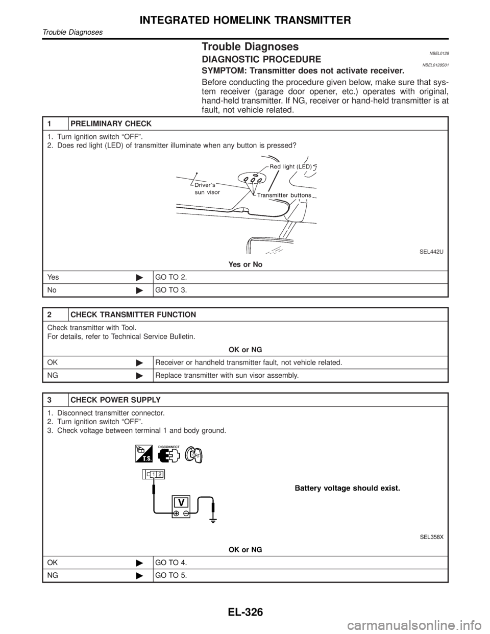
1 PRELIMINARY CHECK
1. Turn ignition switch ªOFFº.
2. Does red light (LED) of transmitter illuminate when any button is pressed?
SEL442U
YesorNo
Ye s©GO TO 2.
No©GO TO 3.
2 CHECK TRANSMITTER FUNCTION
Check transmitter with Tool.
For details, refer to Technical Service Bulletin.
OK or NG
OK©Receiver or handheld transmitter fault, not vehicle related.
NG©Replace transmitter with sun visor assembly.
3 CHECK POWER SUPPLY
1. Disconnect transmitter connector.
2. Turn ignition switch ªOFFº.
3. Check voltage between terminal 1 and body ground.
SEL358X
OK or NG
OK©GO TO 4.
NG©GO TO 5.
INTEGRATED HOMELINK TRANSMITTER
Trouble Diagnoses
EL-326
Page 1512 of 2395

4 CHECK GROUND CIRCUIT
Check continuity between terminal 2 and ground.
SEL359X
OK or NG
OK©Replace transmitter with sun visor assembly.
NG©Repair harness.
5 CHECK MAIN POWER SUPPLY FOR SMART ENTRANCE CONTROL UNIT
1. Disconnect smart entrance control unit.
2. Check voltage between smart entrance control unit terminal 10 and ground.
SEL360X
OK or NG
OK©GO TO 6.
NG©Check the following.
I7.5A fuse No. 24, located in fuse block (J/B)
6 CHECK GROUND CIRCUIT FOR SMART ENTRANCE CONTROL UNIT
Check continuity between terminal 16 and ground.
SEL361X
OK or NG
OK©Power supply and ground circuits are OK.
NG©Check ground harness.
GI
MA
EM
LC
EC
FE
AT
TF
PD
AX
SU
BR
ST
RS
BT
HA
SC
IDX
INTEGRATED HOMELINK TRANSMITTER
Trouble Diagnoses (Cont'd)
EL-327
Page 1643 of 2395

Code Section Wiring Diagram Name
NAVI EL Navigation System
NONDTC AT Non-detectable Items
O2H1B1 EC Heated Oxygen Sensor 1 Heater
(Front) (Bank 1)
O2H1B2 EC Heated Oxygen Sensor 1 Heater
(Front) (Bank 2)
O2H2B1 EC Heated Oxygen Sensor 2 Heater
(Rear) (Bank 1)
O2H2B2 EC Heated Oxygen Sensor 2 Heater
(Rear) (Bank 2)
O2S1B1 EC Heated Oxygen Sensor 1 (Front)
(Bank 1)
O2S1B2 EC Heated Oxygen Sensor 1 (Front)
(Bank 2)
O2S2B1 EC Heated Oxygen Sensor 2 (Rear)
(Bank 1)
O2S2B2 EC Heated Oxygen Sensor 2 (Rear)
(Bank 2)
OVRCSV AT Overrun Clutch Solenoid Valve
P/ANT EL Power Antenna
PGC/V EC EVAP Canister Purge Volume
Control Solenoid Valve
PHASE EC Camshaft Position Sensor
(PHASE)
PNP/SW EC Park/Neutral Position Switch
PNP/SW AT Park/Neutral Position Switch
POS EC Crankshaft Position Sensor
(CKPS) (POS)
POWER EL Power Supply Routing
PRE/SE EC EVAP Control System Pressure
Sensor
PST/SW EC Power Steering Oil Pressure
Switch
REF EC Crankshaft Position Sensor
(CKPS) (REF)
REMOTE EL Audio (Remote Control Switch)
RP/SEN EC Refrigerant Pressure
S/SIG EC Start Signal
S/VCSW EC Swirl Control Valve Control
Vacuum Check Switch
SEAT EL Power Seat
SHIFT AT A/T Shift Lock System
SROOF EL Sunroof
SRS RS Supplemental Restraint SystemCode Section Wiring Diagram Name
SSV/A AT Shift Solenoid Valve A
SSV/B AT Shift Solenoid Valve B
START SC Starting System
STOP/L EL Stop lamp
SWL/V EC Swirl Control Valve Control Sole-
noid Valve
TAIL/L EL Parking, License and Tail Lamps
TCCSIG AT A/T TCC Signal (Lock up)
TCV AT Torque Converter Clutch Solenoid
Valve
T/F TF Transfer
TFTS EC Tank Fuel Temperature Sensor
THEFT EL Theft Warning System
TLID EL Glass Hatch Opener
TP/SW EC Throttle Position Switch
TPS AT Throttle Position Sensor
TPS EC Throttle Position Sensor
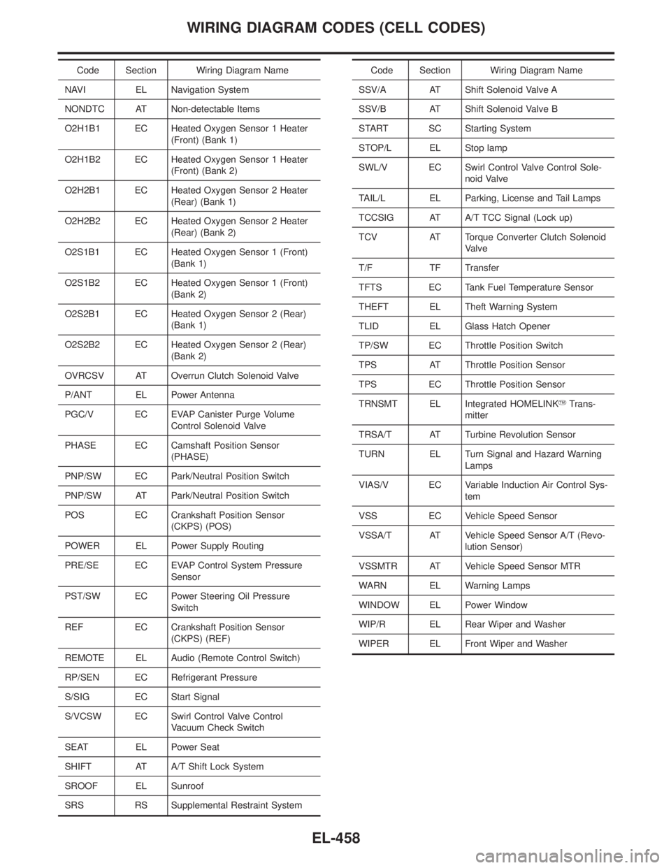
TRNSMT EL Integrated HOMELINKYTrans-
mitter
TRSA/T AT Turbine Revolution Sensor
TURN EL Turn Signal and Hazard Warning
Lamps
VIAS/V EC Variable Induction Air Control Sys-
tem
VSS EC Vehicle Speed Sensor
VSSA/T AT Vehicle Speed Sensor A/T (Revo-
lution Sensor)
VSSMTR AT Vehicle Speed Sensor MTR
WARN EL Warning Lamps
WINDOW EL Power Window
WIP/R EL Rear Wiper and Washer
WIPER EL Front Wiper and Washer
WIRING DIAGRAM CODES (CELL CODES)
EL-458
Page 1964 of 2395

Fusible link ......................................................EL-16
G
Garage jack and safety stand .........................GI-46
Gauges............................................................EL-94
Generator - See Alternator .............................SC-28
Generic scan tool (GST) ................................EC-95
Glass ...............................................................BT-18
Glass hatch opener, electric .........................EL-178
Grease ............................................................MA-11
Ground distribution..........................................EL-17
H
Harness connector ............................................EL-5
Harness connector inspection .........................GI-21
Harness layout ..............................................EL-440
Hazard warning lamp ......................................EL-75
Headlamp ........................................................EL-31
Headlamp aiming control ................................EL-59
Headlining - See Roof trim .............................BT-32
Heated seat .......................................BT-43, EL-183
Height (Dimensions) ........................................GI-43
HFC134a (R134a) system precaution .............HA-2
HFC134a (R134a) system service
procedure ..................................................HA-144
HFC134a (R134a) system service tools ........HA-11
HFC134a system service equipment
precaution .....................................................HA-7
High clutch.....................................................AT-317
H/LAMP - Wiring diagram ...............................EL-36
Hood................................................................BT-12
Horn ..............................................................EL-147
HORN - Wiring diagram................................EL-147
How to erase DTC for OBD system...............EC-72
HSEAT - Wiring diagram...............................EL-183
I
IACV-AAC valve ...........................................EC-422
IATS - Wiring diagram ..................................EC-166
Identification .....................................................HA-4
Identification plate............................................GI-42
Idle air control valve (IACV) .........................EC-422
Idle mixture ratio.............................................EC-43
Idle speed .......................................................EC-43
IGN/SG - Wiring diagram .............................EC-501
Ignition control system .................................EC-499
Ignition timing .................................................EC-43
ILL - Wiring diagram .......................................EL-83
Illumination ......................................................EL-80
In vehicle sensor ..........................................HA-132
INFINITI COMMUNICATOR..........................EL-348
Infiniti communicator (IVCS) .........................EL-348
INJECT - Wiring diagram .............................EC-617
Injector ..........................................................EC-616Injector removal and installation ....................EC-41
Instrument panel .............................................BT-21
INT/L - Wiring diagram....................................EL-91
Intake air temparature sensor ......................EC-164
Intake door control linkage adjustment ..........HA-94
Intake door motor ...........................................HA-87
Intake manifold...............................................EM-12
Intake sensor ................................................HA-139
Integrated homelink transmitter ....................EL-325
Interior .............................................................BT-28
Interior lamp ....................................................EL-88
Interior lamp on-off control ..............................EL-89
Internal gear (Transfer) .................................TF-134
IVC-L - Wiring diagram.................................EC-453
IVC-R - Wiring diagram ................................EC-453
IVCS - Wiring diagram ..................................EL-359
IVCS-L - Wiring diagram ..............................EC-485
IVCS-R - Wiring diagram .............................EC-485
IVIS (Infiniti vehicle immobilizer
system) ......................................................EL-328
IVIS (Infiniti vehicle immobilizer sys-
tem) precautions ............................................GI-3
J
Jacking points ..................................................GI-45
Journal bearing assembly (propeller
shaft) .............................................................PD-9
Journal bearing disassembly (propeller
shaft) .............................................................PD-8
Junction box (J/B).........................................Foldout
K
Keyless entry system - See Multi-re-
mote control system ..................................EL-270
Knock sensor (KS) .......................................EC-328
Knuckle spindle ................................................AX-9
KS - Wiring diagram .....................................EC-330
L
Length (Dimensions) .......................................GI-43
License lamp ...................................................EL-61
Lifting points ....................................................GI-47
Limited slip diff. adjustment ............................PD-50
Limited slip diff. assembly ..............................PD-51
Limited slip diff. disassembly..........................PD-48
Limited slip diff. inspection .............................PD-49
Line pressure solenoid valve ........AT-147, 161, 167
Line pressure switch (Transfer) .....................TF-111
Line pressure test (A/T) ..................................AT-62
Liquid gasket application .................................EM-3
LOAD - Wiring diagram ................................EC-643
Location of electrical units ............................EL-436
Lock, door .......................................................BT-18
Low and reverse brake .................................AT-324
GI
MA
EM
LC
EC
FE
AT
TF
PD
AX
SU
BR
ST
RS
BT
HA
SC
EL
ALPHABETICAL INDEX
IDX-5