relay INFINITI QX4 2001 Factory Service Manual
[x] Cancel search | Manufacturer: INFINITI, Model Year: 2001, Model line: QX4, Model: INFINITI QX4 2001Pages: 2395, PDF Size: 43.2 MB
Page 37 of 2395

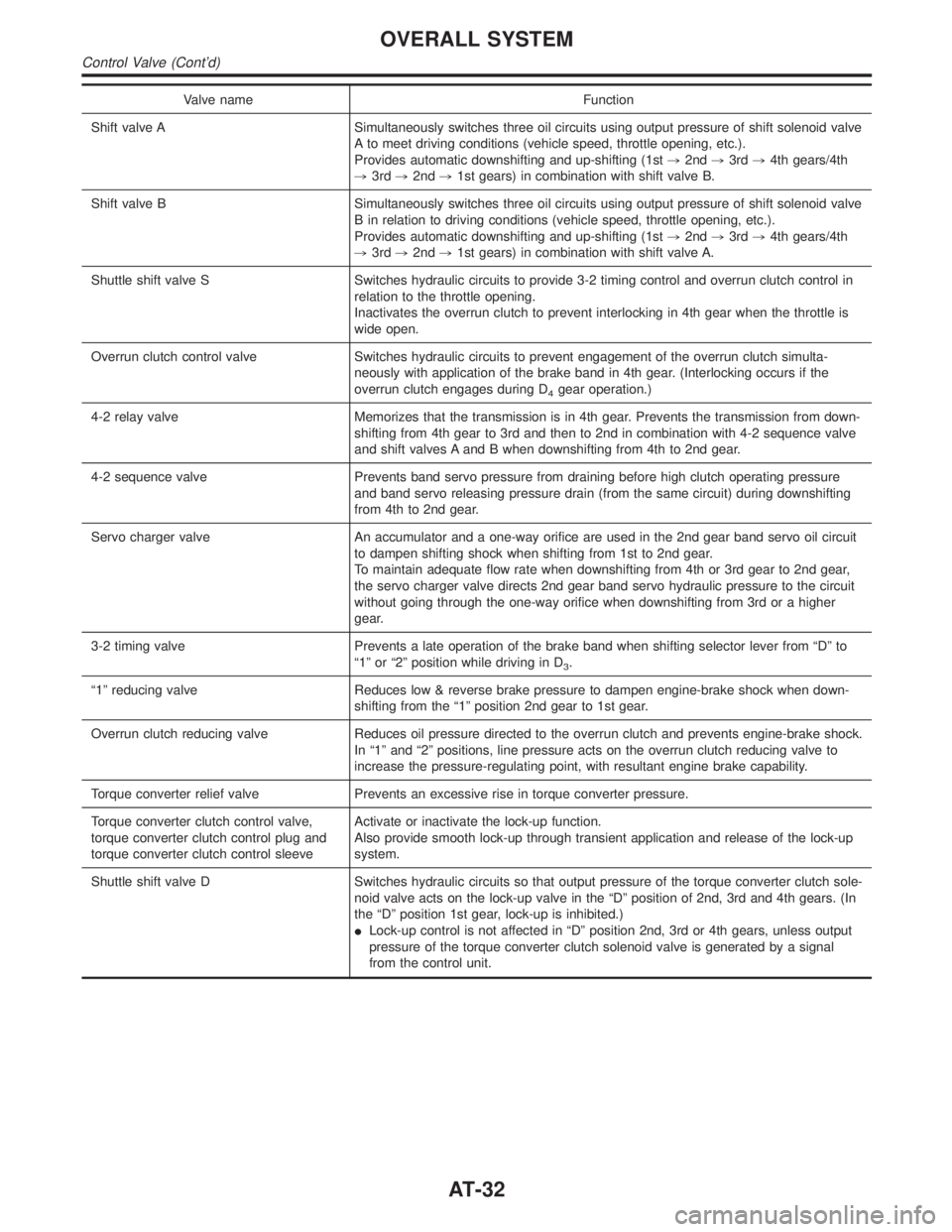
Valve name Function
Shift valve A Simultaneously switches three oil circuits using output pressure of shift solenoid valve
A to meet driving conditions (vehicle speed, throttle opening, etc.).
Provides automatic downshifting and up-shifting (1st,2nd,3rd,4th gears/4th
,3rd,2nd,1st gears) in combination with shift valve B.
Shift valve B Simultaneously switches three oil circuits using output pressure of shift solenoid valve
B in relation to driving conditions (vehicle speed, throttle opening, etc.).
Provides automatic downshifting and up-shifting (1st,2nd,3rd,4th gears/4th
,3rd,2nd,1st gears) in combination with shift valve A.
Shuttle shift valve S Switches hydraulic circuits to provide 3-2 timing control and overrun clutch control in
relation to the throttle opening.
Inactivates the overrun clutch to prevent interlocking in 4th gear when the throttle is
wide open.
Overrun clutch control valve Switches hydraulic circuits to prevent engagement of the overrun clutch simulta-
neously with application of the brake band in 4th gear. (Interlocking occurs if the
overrun clutch engages during D
4gear operation.)
4-2 relay valve Memorizes that the transmission is in 4th gear. Prevents the transmission from down-
shifting from 4th gear to 3rd and then to 2nd in combination with 4-2 sequence valve
and shift valves A and B when downshifting from 4th to 2nd gear.
4-2 sequence valve Prevents band servo pressure from draining before high clutch operating pressure
and band servo releasing pressure drain (from the same circuit) during downshifting
from 4th to 2nd gear.
Servo charger valve An accumulator and a one-way orifice are used in the 2nd gear band servo oil circuit
to dampen shifting shock when shifting from 1st to 2nd gear.
To maintain adequate flow rate when downshifting from 4th or 3rd gear to 2nd gear,
the servo charger valve directs 2nd gear band servo hydraulic pressure to the circuit
without going through the one-way orifice when downshifting from 3rd or a higher
gear.
3-2 timing valve Prevents a late operation of the brake band when shifting selector lever from ªDº to
ª1º or ª2º position while driving in D
3.
ª1º reducing valve Reduces low & reverse brake pressure to dampen engine-brake shock when down-
shifting from the ª1º position 2nd gear to 1st gear.
Overrun clutch reducing valve Reduces oil pressure directed to the overrun clutch and prevents engine-brake shock.
In ª1º and ª2º positions, line pressure acts on the overrun clutch reducing valve to
increase the pressure-regulating point, with resultant engine brake capability.
Torque converter relief valve Prevents an excessive rise in torque converter pressure.
Torque converter clutch control valve,
torque converter clutch control plug and
torque converter clutch control sleeveActivate or inactivate the lock-up function.
Also provide smooth lock-up through transient application and release of the lock-up
system.
Shuttle shift valve D Switches hydraulic circuits so that output pressure of the torque converter clutch sole-
noid valve acts on the lock-up valve in the ªDº position of 2nd, 3rd and 4th gears. (In
the ªDº position 1st gear, lock-up is inhibited.)
ILock-up control is not affected in ªDº position 2nd, 3rd or 4th gears, unless output
pressure of the torque converter clutch solenoid valve is generated by a signal
from the control unit.
OVERALL SYSTEM
Control Valve (Cont'd)
AT-32
Page 274 of 2395

7 CHECK GROUND CIRCUIT
1. Turn ignition switch to OFF position.
2. Disconnect A/T device harness connector.
3. Check continuity between A/T device harness terminal 6 and ground. Refer to wiring diagram Ð SHIFT Ð.
Continuity should exist.
If OK, check harness for short to ground and short to power.
OK or NG
OK©GO TO 8.
NG©Repair open circuit or short to ground or short to power in harness or connectors.
8 CHECK RELAY CIRCUIT
1. Turn ignition switch to ON and OFF position.
ICheck continuity between terminals 1, 2, 3 and 5.
SAT775J
YesorNo
Ye s©GO TO 9.
No©Replace relay.
9 CHECK PARK POSITION SWITCH
ICheck continuity between A/T device harness terminal 6 and relay (park position switch) harness terminal 1.
SAT180K
OK or NG
OK©GO TO 10.
NG©Replace park position switch.
GI
MA
EM
LC
EC
FE
TF
PD
AX
SU
BR
ST
RS
BT
HA
SC
EL
IDX
A/T SHIFT LOCK SYSTEM
Diagnostic Procedure (Cont'd)
AT-269
Page 314 of 2395

SAT826A
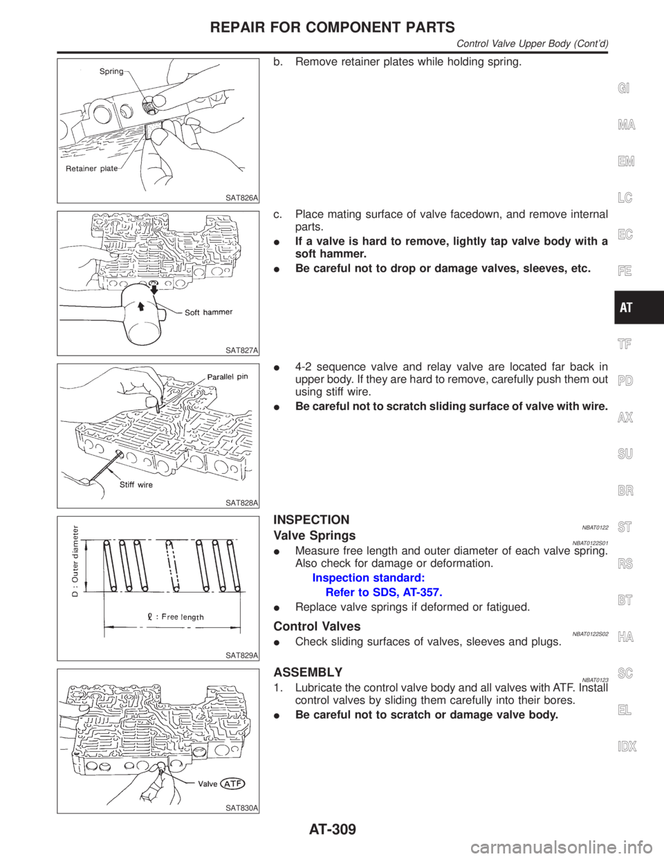
b. Remove retainer plates while holding spring.
SAT827A
c. Place mating surface of valve facedown, and remove internal
parts.
IIf a valve is hard to remove, lightly tap valve body with a
soft hammer.
IBe careful not to drop or damage valves, sleeves, etc.
SAT828A
I4-2 sequence valve and relay valve are located far back in
upper body. If they are hard to remove, carefully push them out
using stiff wire.
IBe careful not to scratch sliding surface of valve with wire.
SAT829A
INSPECTIONNBAT0122Valve SpringsNBAT0122S01IMeasure free length and outer diameter of each valve spring.
Also check for damage or deformation.
Inspection standard:
Refer to SDS, AT-357.
IReplace valve springs if deformed or fatigued.
Control ValvesNBAT0122S02ICheck sliding surfaces of valves, sleeves and plugs.
SAT830A
ASSEMBLYNBAT01231. Lubricate the control valve body and all valves with ATF. Install
control valves by sliding them carefully into their bores.
IBe careful not to scratch or damage valve body.
GI
MA
EM
LC
EC
FE
TF
PD
AX
SU
BR
ST
RS
BT
HA
SC
EL
IDX
REPAIR FOR COMPONENT PARTS
Control Valve Upper Body (Cont'd)
AT-309
Page 316 of 2395

SAT835A
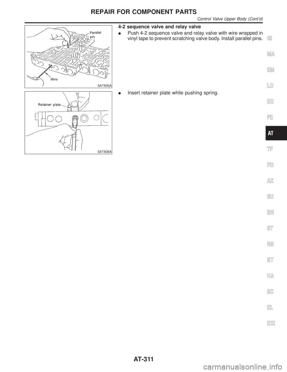
4-2 sequence valve and relay valve
IPush 4-2 sequence valve and relay valve with wire wrapped in
vinyl tape to prevent scratching valve body. Install parallel pins.
SAT836A
IInsert retainer plate while pushing spring.
GI
MA
EM
LC
EC
FE
TF
PD
AX
SU
BR
ST
RS
BT
HA
SC
EL
IDX
REPAIR FOR COMPONENT PARTS
Control Valve Upper Body (Cont'd)
AT-311
Page 362 of 2395

Return SpringsNBAT0165Unit: mm (in)
PartsItem
Part No.* Free length Outer diameter
Control valveUpper body1 Torque converter relief valve spring 31742-41X23 38.0 (1.496) 9.0 (0.354)
2 Pressure regulator valve spring 31742-41X24 44.02 (1.7331) 14.0 (0.551)
3 Pressure modifier valve spring 31742-41X19 31.95 (1.2579) 6.8 (0.268)
Ð Accumulator control valve spring Ð Ð Ð
4 Shuttle shift valve D spring 31762-41X01 25.0 (0.984) 7.0 (0.276)
5 4-2 sequence valve spring 31756-41X00 29.1 (1.146) 6.95 (0.2736)
6 Shift valve B spring 31762-41X01 25.0 (0.984) 7.0 (0.276)
7 4-2 relay valve spring 31756-41X00 29.1 (1.146) 6.95 (0.2736)
8 Shift valve A spring 31762-41X01 25.0 (0.984) 7.0 (0.276)
9 Overrun clutch control valve spring 31762-41X03 23.6 (0.929) 7.0 (0.276)
10 Overrun clutch reducing valve spring 31742-41X14 38.9 (1.531) 7.0 (0.276)
11 Shuttle shift valve S spring 31762-41X04 51.0 (2.008) 5.65 (0.2224)
12 Pilot valve spring 31742-41X13 25.7 (1.012) 9.0 (0.354)
13 Torque converter clutch control valve spring 31742-41X22 18.5 (0.728) 13.0 (0.512)
Lower body1 Modifier accumulator piston spring 31742-27X70 31.4 (1.236) 9.8 (0.386)
2 1st reducing valve spring 31756-60X00 20.5 (0.807) 7.0 (0.276)
3 3-2 timing valve spring 31742-41X06 23.0 (0.906) 6.7 (0.264)
4 Servo charger valve spring 31742-41X06 23.0 (0.906) 6.7 (0.264)
Reverse clutch Ð 31505-41X07 Ð Ð
High clutch10 pcs31521-41X03
(Assembly)24.2 (0.9528) 11.6 (0.457)
Forward clutch (Overrun clutch) 20 pcs31521-41X04
(Assembly)35.77 (1.4083) 9.7 (0.382)
Low & reverse brake 18 pcs31655-41X00
(Assembly)22.3 (0.878) 11.2 (0.441)
Band servoSpring A 31605-4AX03 45.6 (1.795) 34.3 (1.350)
Spring B 31605-41X01 29.7 (1.169) 27.6 (1.087)
AccumulatorAccumulator A 31605-41X02 43.0 (1.693) 18.0 (0.709)
Accumulator B 31605-41X14 47.6 (1.874) 26.5 (1.043)
Accumulator C 31605-41X09 45.0 (1.772) 29.3 (1.154)
Accumulator D 31605-41X06 58.4 (2.299) 17.3 (0.681)
GI
MA
EM
LC
EC
FE
TF
PD
AX
SU
BR
ST
RS
BT
HA
SC
EL
IDX
SERVICE DATA AND SPECIFICATIONS (SDS)
Return Springs
AT-357
Page 391 of 2395

ABS
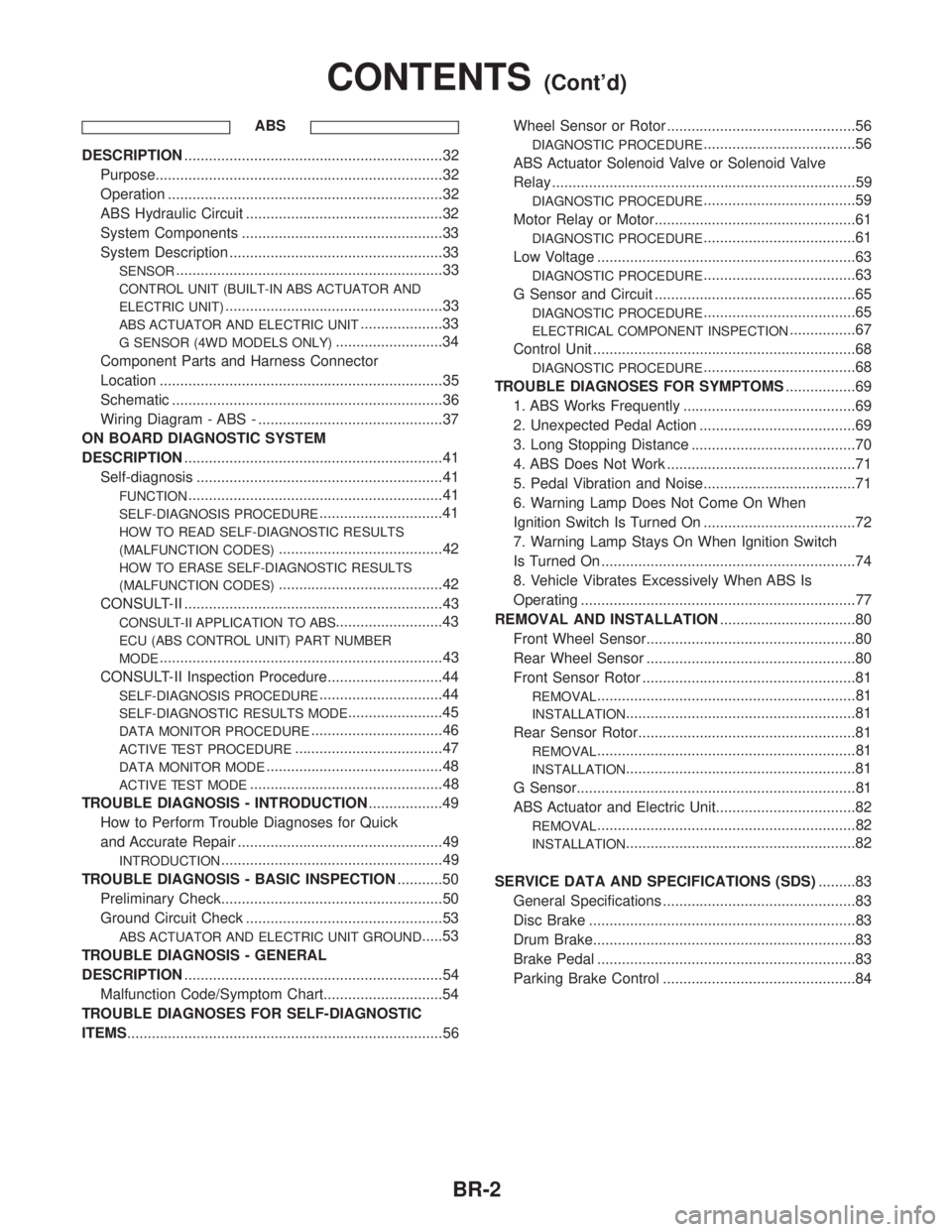
DESCRIPTION...............................................................32
Purpose......................................................................32
Operation ...................................................................32
ABS Hydraulic Circuit ................................................32
System Components .................................................33
System Description ....................................................33
SENSOR.................................................................33
CONTROL UNIT (BUILT-IN ABS ACTUATOR AND
ELECTRIC UNIT)
.....................................................33
ABS ACTUATOR AND ELECTRIC UNIT....................33
G SENSOR (4WD MODELS ONLY)..........................34
Component Parts and Harness Connector
Location .....................................................................35
Schematic ..................................................................36
Wiring Diagram - ABS - .............................................37
ON BOARD DIAGNOSTIC SYSTEM
DESCRIPTION...............................................................41
Self-diagnosis ............................................................41
FUNCTION..............................................................41
SELF-DIAGNOSIS PROCEDURE..............................41
HOW TO READ SELF-DIAGNOSTIC RESULTS
(MALFUNCTION CODES)
........................................42
HOW TO ERASE SELF-DIAGNOSTIC RESULTS
(MALFUNCTION CODES)
........................................42
CONSULT-II ...............................................................43
CONSULT-II APPLICATION TO ABS..........................43
ECU (ABS CONTROL UNIT) PART NUMBER
MODE
.....................................................................43
CONSULT-II Inspection Procedure............................44
SELF-DIAGNOSIS PROCEDURE..............................44
SELF-DIAGNOSTIC RESULTS MODE.......................45
DATA MONITOR PROCEDURE................................46
ACTIVE TEST PROCEDURE....................................47
DATA MONITOR MODE...........................................48
ACTIVE TEST MODE...............................................48
TROUBLE DIAGNOSIS - INTRODUCTION..................49
How to Perform Trouble Diagnoses for Quick
and Accurate Repair ..................................................49
INTRODUCTION......................................................49
TROUBLE DIAGNOSIS - BASIC INSPECTION...........50
Preliminary Check......................................................50
Ground Circuit Check ................................................53
ABS ACTUATOR AND ELECTRIC UNIT GROUND.....53
TROUBLE DIAGNOSIS - GENERAL
DESCRIPTION...............................................................54
Malfunction Code/Symptom Chart.............................54
TROUBLE DIAGNOSES FOR SELF-DIAGNOSTIC
ITEMS.............................................................................56Wheel Sensor or Rotor ..............................................56
DIAGNOSTIC PROCEDURE.....................................56
ABS Actuator Solenoid Valve or Solenoid Valve
Relay ..........................................................................59
DIAGNOSTIC PROCEDURE.....................................59
Motor Relay or Motor.................................................61
DIAGNOSTIC PROCEDURE.....................................61
Low Voltage ...............................................................63
DIAGNOSTIC PROCEDURE.....................................63
G Sensor and Circuit .................................................65
DIAGNOSTIC PROCEDURE.....................................65
ELECTRICAL COMPONENT INSPECTION................67
Control Unit ................................................................68
DIAGNOSTIC PROCEDURE.....................................68
TROUBLE DIAGNOSES FOR SYMPTOMS.................69
1. ABS Works Frequently ..........................................69
2. Unexpected Pedal Action ......................................69
3. Long Stopping Distance ........................................70
4. ABS Does Not Work ..............................................71
5. Pedal Vibration and Noise.....................................71
6. Warning Lamp Does Not Come On When
Ignition Switch Is Turned On .....................................72
7. Warning Lamp Stays On When Ignition Switch
Is Turned On ..............................................................74
8. Vehicle Vibrates Excessively When ABS Is
Operating ...................................................................77
REMOVAL AND INSTALLATION.................................80
Front Wheel Sensor...................................................80
Rear Wheel Sensor ...................................................80
Front Sensor Rotor ....................................................81
REMOVAL...............................................................81
INSTALLATION........................................................81
Rear Sensor Rotor.....................................................81
REMOVAL...............................................................81
INSTALLATION........................................................81
G Sensor....................................................................81
ABS Actuator and Electric Unit..................................82
REMOVAL...............................................................82
INSTALLATION........................................................82
SERVICE DATA AND SPECIFICATIONS (SDS).........83
General Specifications ...............................................83
Disc Brake .................................................................83
Drum Brake................................................................83
Brake Pedal ...............................................................83
Parking Brake Control ...............................................84
CONTENTS(Cont'd)
BR-2
Page 422 of 2395

System ComponentsNBBR0090
SBR447EB
SBR124B
System DescriptionNBBR0091SENSORNBBR0091S01The sensor unit consists of a gear-shaped sensor rotor and a sen-
sor element. The element contains a bar magnet around which a
coil is wound. The front sensors are installed on the front spindles
and the rear sensors are installed on the rear spindles. As the
wheel rotates, the sensor generates a sine-wave pattern. The fre-
quency and voltage increase(s) as the rotating speed increases.
SBR668E
CONTROL UNIT (BUILT-IN ABS ACTUATOR AND
ELECTRIC UNIT)
NBBR0091S02The control unit computes the wheel rotating speed by the signal
current sent from the sensor. Then it supplies a DC current to the
actuator solenoid valve. It also controls ON-OFF operation of the
valve relay and motor relay. If any electrical malfunction should be
detected in the system, the control unit causes the warning lamp
to light up. In this condition, the ABS will be deactivated by the
control unit, and the vehicle's brake system reverts to normal
operation. (For control unit layout, refer to ABS ACTUATOR AND
ELECTRIC UNIT, BR-33.)
SBR482E
ABS ACTUATOR AND ELECTRIC UNITNBBR0091S03The ABS actuator and electric unit contains:
IAn electric motor and pump
ITwo relays
ISix solenoid valves, each inlet and outlet for
Ð LH front
Ð RH front
Ð Rear
IABS control unit
GI
MA
EM
LC
EC
FE
AT
TF
PD
AX
SU
ST
RS
BT
HA
SC
EL
IDX
DESCRIPTIONABS
System Components
BR-33
Page 432 of 2395

CONSULT-II=NBBR0096CONSULT-II APPLICATION TO ABSNBBR0096S01
ITEMSELF-DIAGNOSTIC
RESULTSDATA MONITOR ACTIVE TEST
Front right wheel sensor´´Ð
Front left wheel sensor´´Ð
Rear right wheel sensor´´Ð
Rear left wheel sensor´´Ð
G switch (G sensor)H´´´
ABS sensor´ÐÐ
Stop lamp switch дÐ
Front right inlet solenoid valve´´´
Front right outlet solenoid valve´´´
Front left inlet solenoid valve´´´
Front left outlet solenoid valve´´´
Rear inlet solenoid valve´´´
Rear outlet solenoid valve´´´
Actuator solenoid valve relay´´Ð
Actuator motor relay
(ABS MOTOR is shown on the Data Monitor
screen.)´´´
ABS warning lamp дÐ
Battery voltage´´Ð
Control unit´ÐÐ
ABS operating signal д´
´: Applicable
Ð: Not applicable
H: 4WD models only
ECU (ABS CONTROL UNIT) PART NUMBER MODENBBR0096S02Ignore the ECU part number displayed in the ECU PART NUMBER MODE. Refer to parts catalog to order
the ECU.
GI
MA
EM
LC
EC
FE
AT
TF
PD
AX
SU
ST
RS
BT
HA
SC
EL
IDX
ON BOARD DIAGNOSTIC SYSTEM DESCRIPTIONABS
CONSULT-II
BR-43
Page 434 of 2395
![INFINITI QX4 2001 Factory Service Manual SELF-DIAGNOSTIC RESULTS MODENBBR0097S02
Diagnostic item Diagnostic item is detected when ... Reference Page
FR RH SENSOR*1
[OPEN]ICircuit for front right wheel sensor is open.
(An abnormally high inpu INFINITI QX4 2001 Factory Service Manual SELF-DIAGNOSTIC RESULTS MODENBBR0097S02
Diagnostic item Diagnostic item is detected when ... Reference Page
FR RH SENSOR*1
[OPEN]ICircuit for front right wheel sensor is open.
(An abnormally high inpu](/img/42/57027/w960_57027-433.png)
SELF-DIAGNOSTIC RESULTS MODENBBR0097S02
Diagnostic item Diagnostic item is detected when ... Reference Page
FR RH SENSOR*1
[OPEN]ICircuit for front right wheel sensor is open.
(An abnormally high input voltage is entered.)BR-56
FR LH SENSOR*1
[OPEN]ICircuit for front left wheel sensor is open.
(An abnormally high input voltage is entered.)BR-56
RR RH SENSOR*1
[OPEN]ICircuit for rear right sensor is open.
(An abnormally high input voltage is entered.)BR-56
RR LH SENSOR*1
[OPEN]ICircuit for rear left sensor is open.
(An abnormally high input voltage is entered.)BR-56
FR RH SENSOR*1
[SHORT]ICircuit for front right wheel sensor is shorted.
(An abnormally low input voltage is entered.)BR-56
FR LH SENSOR*1
[SHORT]ICircuit for front left wheel sensor is shorted.
(An abnormally low input voltage is entered.)BR-56
RR RH SENSOR*1
[SHORT]ICircuit for rear right sensor is shorted.
(An abnormally low input voltage is entered.)BR-56
RR LH SENSOR*1
[SHORT]ICircuit for rear left sensor is shorted.
(An abnormally low input voltage is entered.)BR-56
ABS SENSOR*1
[ABNORMAL SIGNAL]ITeeth damage on sensor rotor or improper installation of wheel sensor.
(Abnormal wheel sensor signal is entered.)BR-56
FR RH IN ABS SOL
[OPEN, SHORT]ICircuit for front right inlet solenoid valve is open.
(An abnormally low output voltage is entered.)BR-59
FR LH IN ABS SOL
[OPEN, SHORT]ICircuit for front left inlet solenoid valve is open.
(An abnormally low output voltage is entered.)BR-59
FR RH OUT ABS SOL
[OPEN, SHORT]ICircuit for front right outlet solenoid valve is open.
(An abnormally low output voltage is entered.)BR-59
FR LH OUT ABS SOL
[OPEN, SHORT]ICircuit for front left outlet solenoid valve is open.
(An abnormally low output voltage is entered.)BR-59
RR IN ABS SOL
[OPEN, SHORT]ICircuit for rear inlet solenoid valve is shorted.
(An abnormally high output voltage is entered.)BR-59
RR OUT ABS SOL
[OPEN, SHORT]ICircuit for rear out solenoid valve is shorted.
(An abnormally high output voltage is entered.)BR-59
ABS ACTUATOR RELAY
[ABNORMAL]IActuator solenoid valve relay is ON, even if control unit sends off signal.
IActuator solenoid valve relay is OFF, even if control unit sends on signal.BR-59
ABS MOTOR RELAY
[ABNORMAL]ICircuit for ABS motor relay is open or shorted.
ICircuit for actuator motor is open or shorted.
IActuator motor relay is stuck.BR-61
BATTERY VOLT
[VB-LOW]IPower source voltage supplied to ABS control unit is abnormally low.
BR-63
CONTROL UNITIFunction of calculation in ABS control unit has failed. BR-68
G SENSOR*2
[ABNORMAL]IG sensor circuit is open or shorted.
BR-65
*1: If one or more wheels spin on a rough or slippery road for 40 seconds or more, the ABS warning lamp will illuminate. This does not
indicate a malfunction. Only in the case of the short-circuit (Code Nos. 26, 22, 32 and 36), after repair the ABS warning lamp also illu-
minates when the ignition switch is turned ON. In this case, drive the vehicle at speeds greater than 30 km/h (19 MPH) for approxi-
mately 1 minute as specified in ªSELF-DIAGNOSIS PROCEDUREº, BR-41. Check to ensure that the ABS warning lamp goes out while
the vehicle is being driven.
*2: 4WD models onlyGI
MA
EM
LC
EC
FE
AT
TF
PD
AX
SU
ST
RS
BT
HA
SC
EL
IDX
ON BOARD DIAGNOSTIC SYSTEM DESCRIPTIONABS
CONSULT-II Inspection Procedure (Cont'd)
BR-45
Page 437 of 2395

DATA MONITOR MODENBBR0097S05
MONITOR ITEM CONDITION SPECIFICATION
FR RH SENSOR
FR LH SENSOR
RR RH SENSOR
RR LH SENSORDrive vehicle.
(Each wheel is rotating.)Wheel speed signal
(Almost the same speed as speedometer.)
STOP LAMP SW Brake is depressed.Depress the pedal: ON
Release the pedal: OFF
G-SWITCHHVehicle is driven.
Vehicle is stopped.
Brake is applied.During sudden braking while driving on high roads (asphalt
roads, etc.): OFF
While vehicle is stopped or during constant-speed driving: ON
FR RH IN SOL
FR RH OUT SOL
FR LH IN SOL
FR LH OUT SOL
RR IN SOL
RR OUT SOL1. Drive vehicle at speeds
over 30 km/h (19 MPH) for at
least 1 minute.
2. Engine is running.Operating conditions for each solenoid valve are indicated. ABS
is not operating: OFF
MOTOR RELAYABS is not operating: OFF
ABS is operating: ON
ACTUATOR RELAY
Ignition switch is ON or
engine is running.Ignition switch ON (Engine stops): OFF
Engine running: ON
WARNING LAMPABS warning lamp is turned on: ON
ABS warning lamp is turned off: OFF
BATTERY VOLT Power supply voltage for control unit
ABS OPER SIGABS is not operating: OFF
ABS is operating: ON
H: 4WD model only
ACTIVE TEST MODENBBR0097S06
TEST ITEM CONDITION JUDGEMENT
FR RH SOLENOID
FR LH SOLENOID
RR SOLENOID
Engine is running.Brake fluid pressure control operation
IN SOL OUT SOL
UP (Increase): OFF OFF
KEEP (Hold): ON OFF
DOWN (Decrease): ON ON
ABS MOTORABS actuator motor
ON: Motor runs (ABS motor relay ON)
OFF: Motor stops (ABS motor relay OFF)
ABS OPER SIGIgnition switch is ON or
engine is running.ON: Set ABS OPER SIG ªONº (ABS is operating.)
OFF: Set ABS OPER SIG ªOFFº (ABS is not operating.)
G SWITCHHIgnition switch is ON.G SWITCH (G SENSOR)
ON: Set G SWITCH MONITOR ªONº (G switch circuit is
closed.)
OFF: Set G SWITCH MONITOR ªOFFº (G switch circuit is
open.)
H: 4WD models only
NOTE:
Active test will automatically stop ten seconds after the test starts. (TEST IS STOPPED monitor shows ON.)
ON BOARD DIAGNOSTIC SYSTEM DESCRIPTIONABS
CONSULT-II Inspection Procedure (Cont'd)
BR-48