rear view mirror INFINITI QX50 2021 Owner's Manual
[x] Cancel search | Manufacturer: INFINITI, Model Year: 2021, Model line: QX50, Model: INFINITI QX50 2021Pages: 542, PDF Size: 3.51 MB
Page 15 of 542
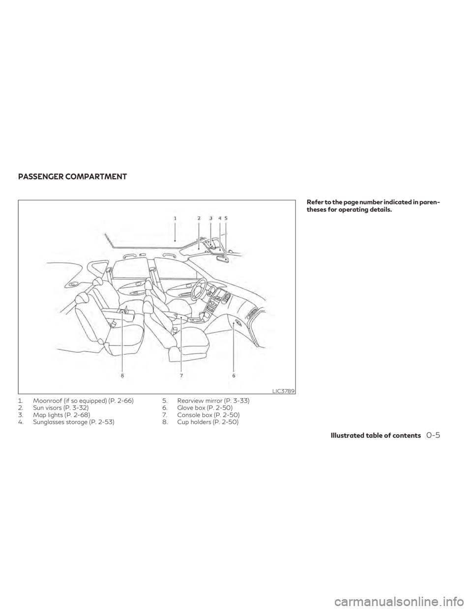
1. Moonroof (if so equipped) (P. 2-66)
2. Sun visors (P. 3-32)
3. Map lights (P. 2-68)
4. Sunglasses storage (P. 2-53)5. Rearview mirror (P. 3-33)
6. Glove box (P. 2-50)
7. Console box (P. 2-50)
8. Cup holders (P. 2-50)
Refer to the page number indicated in paren-
theses for operating details.
LIC3789
PASSENGER COMPARTMENT
Illustrated table of contents0-5
Page 160 of 542
3 Pre-driving checks and adjustments
Keys.............................................3-2
INFINITI Intelligent Key .......................3-2
INFINITI Vehicle Immobilizer System
keys ..........................................3-4
Doors ...........................................3-4
Locking with key ..............................3-4
Locking with inside lock knob Type A
(if so equipped) ...............................3-5
Locking with inside lock knob Type B
(if so equipped) ...............................3-5
Locking with power door lock switch ..........3-5
Automatic door locks .........................3-6
Child safety rear door lock .....................3-6
INFINITI Intelligent Key System ...................3-6
Operating range ..............................3-8
Door locks/unlocks precaution ................3-9
INFINITI Intelligent Key operation .............3-9
How to use the remote keyless entry
function .................................... 3-13
Warning signals ............................. 3-16
Troubleshooting guide ......................3-16
Log-in function ............................. 3-18
Remote Engine Start (if so equipped) ...........3-18
Remote Engine Start operating range ........3-19
Remote starting the vehicle ..................3-19
Extending engine run time ...................3-19
Canceling a Remote Engine Start ............3-20 Conditions the Remote Engine Start will
not work
................................... 3-20
Hood .......................................... 3-21
Liftgate ....................................... 3-21
Operating the power liftgate ................3-22
Motion-Activated Liftgate
(if so equipped) ............................. 3-24
Power liftgate main switch ..................3-26
Liftgate release ............................. 3-26
Liftgate position setting .....................3-27
Fuel-filler door ................................. 3-28
Opening the fuel-filler door ..................3-28
Fuel-filler cap ............................... 3-28
Steering wheel ................................. 3-31
Manual operation (if so equipped) ...........3-31
Automatic operation (if so equipped) .........3-31
Sun visors ..................................... 3-32
Vanity mirrors .............................. 3-33
C
ard holder ................................. 3-33
Mirrors ........................................ 3-33
Manual anti-glare rearview mirror
(if so equipped) ............................. 3-33
Automatic anti-glare rearview mirror
(if so equipped) ............................. 3-34
Outside mirrors ............................. 3-34
Memory Seat (if so equipped) ...................3-36
Page 193 of 542

VANITY MIRRORS
To access the vanity mirror, pull the sun visor
down and flip open the mirror cover. The
vanity mirror will illuminate when the mirror
cover is open.
CARD HOLDER
To use the card holder, slide card into the clip.
Do not view information while operating the
vehicle.
MANUAL ANTI-GLARE
REARVIEW MIRROR (if so
equipped)
Use the night positionO1to reduce glare
from the headlights of vehicles behind you at
night.
Use the day position
O2when driving in day-
light hours.
WARNING
Use the night position only when neces-
sary, because it reduces rear view clarity.
LPD2583
Driver’s and passenger’s side
LPD2340
Driver’s and passenger’s side
WPD0126
MIRRORS
Pre-driving checks and adjustments3-33
Page 194 of 542

AUTOMATIC ANTI-GLARE
REARVIEW MIRROR (if so
equipped)
The inside mirror is designed so that it auto-
matically dims during night time conditions
and according to the intensity of the head-
lights of the vehicle following you. The auto-
matic anti-glare feature is activated when
the ignition switch is in the ON position.
NOTE:
Do not hang any objects over the sensorsO1
or apply glass cleaner to the sensors. Doing
so will reduce the sensitivity of the sensors,
resulting in improper operation.
The indicator light
O2will illuminate when the
automatic anti-glare feature is operating.
To turn off the automatic anti-glare feature,
press the O button. The indicator light will
turn off.
To turn on the automatic anti-glare feature,
press the | button. The indicator light will
turn on.
For additional information on HomeLink®
Universal Transceiver operation, see
“HomeLink® Universal Transceiver”
(P. 2-70).
OUTSIDE MIRRORS
The outside mirror remote control will oper-
ate only when the ignition switch is in the ON
position.
Move the small switch
O1to select the left or
right mirror. Adjust each mirror to the desired
position using the large switch
O2. Move the
small switch
O1to the center (neutral) posi-
tion to prevent accidentally moving the
mirror.
LPD0469LPD3035
3-34Pre-driving checks and adjustments
Page 195 of 542
WARNING
• Objects viewed in the outside mirror on
the passenger side are closer than they
appear. Be careful when moving to the
right. Using only this mirror could cause
an accident. Use the inside mirror or
glance over your shoulder to properly
judge distances to other objects.
• Do not adjust the mirrors while driving.
You could lose control of your vehicle and
cause an accident.
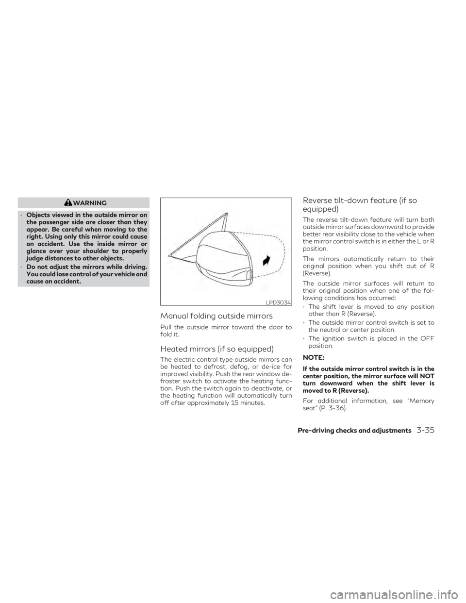
Manual folding outside mirrors
Pull the outside mirror toward the door to
fold it.
Heated mirrors (if so equipped)
The electric control type outside mirrors can
be heated to defrost, defog, or de-ice for
improved visibility. Push the rear window de-
froster switch to activate the heating func-
tion. Push the switch again to deactivate, or
the heating function will automatically turn
off after approximately 15 minutes.
Reverse tilt-down feature (if so
equipped)
The reverse tilt-down feature will turn both
outside mirror surfaces downward to provide
better rear visibility close to the vehicle when
the mirror control switch is in either the L or R
position.
The mirrors automatically return to their
original position when you shift out of R
(Reverse).
The outside mirror surfaces will return to
their original position when one of the fol-
lowing conditions has occurred:
• The shift lever is moved to any position other than R (Reverse).
• The outside mirror control switch is set to the neutral or center position.
• The ignition switch is placed in the OFF position.
NOTE:
If the outside mirror control switch is in the
center position, the mirror surface will NOT
turn downward when the shift lever is
moved to R (Reverse).
For additional information, see “Memory
seat” (P. 3-36).
LPD3034
Pre-driving checks and adjustments3-35
Page 201 of 542
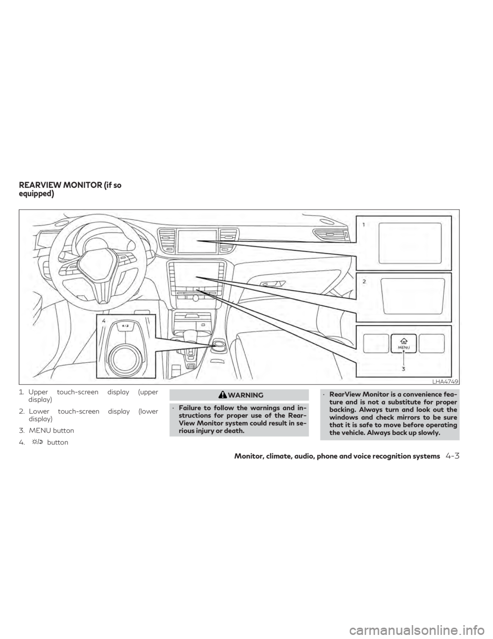
1. Upper touch-screen display (upperdisplay)
2. Lower touch-screen display (lower display)
3. MENU button
4.
button
WARNING
• Failure to follow the warnings and in-
structions for proper use of the Rear-
View Monitor system could result in se-
rious injury or death. •
RearView Monitor is a convenience fea-
ture and is not a substitute for proper
backing. Always turn and look out the
windows and check mirrors to be sure
that it is safe to move before operating
the vehicle. Always back up slowly.
LHA4749
REARVIEW MONITOR (if so
equipped)
Monitor, climate, audio, phone and voice recognition systems4-3
Page 207 of 542
•Objects in the RearView Monitor will ap-
pear visually opposite compared to when
viewed in the rearview and outside
mirrors.
• Use the displayed lines as a reference.
The lines are highly affected by the num-
ber of occupants, fuel level, vehicle posi-
tion, road conditions and road grade.
• Make sure that the liftgate is securely
closed when backing up.
• Do not put anything on the rearview
camera. The rearview camera is installed
above the license plate.
• When washing the vehicle with high
pressure water, be sure not to spray it
around the camera. Otherwise, water
may enter the camera unit causing water
condensation on the lens, a malfunction,
fire or an electric shock.
• Do not strike the camera. It is a precision
instrument. Otherwise, it may malfunc-
tion or cause damage resulting in a fire or
an electric shock. The following are operating limitations and
do not represent a system malfunction:
• When the temperature is extremely high or
low, the screen may not clearly display
objects.
• When strong light directly shines on the camera, objects may not be displayed
clearly.
• Vertical lines may be seen in objects on the screen. This is due to strong reflected light
from the bumper.
• The screen may flicker under fluorescent light.
• The colors of objects on the RearView Monitor may differ somewhat from the ac-
tual color of objects.
• Objects on the monitor may not be clear in a dark environment.
• There may be a delay when switching be- tween views.
• If dirt, rain or snow accumulate on the cam- era, the RearView Monitor may not display
objects clearly. Clean the camera.
• Do not use wax on the camera lens. Wipe off any wax with a clean cloth dampened
with a diluted mild cleaning agent, then
wipe with a dry cloth.
SYSTEM MAINTENANCE
CAUTION
• Do not use alcohol, benzine or thinner to
clean the camera. This will cause
discoloration.
• Do not damage the camera as the moni-
tor screen may be adversely affected.
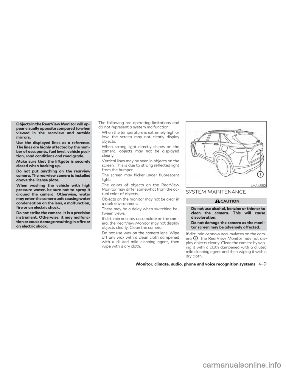
If dirt, rain or snow accumulates on the cam-
era
O1, the RearView Monitor may not dis-
play objects clearly. Clean the camera by wip-
ing it with a cloth dampened with a diluted
mild cleaning agent and then wiping it with a
dry cloth.
LHA4552
Monitor, climate, audio, phone and voice recognition systems4-9
Page 209 of 542
WARNING
• Failure to follow the warnings and in-
structions for the proper use of the
Around View® Monitor system could re-
sult in serious injury or death.
• The Around View® Monitor is a conve-
nience feature and is not a substitute for
proper vehicle operation because it has
areas where objects cannot be viewed.
The four corners of the vehicle in particu-
lar, are areas where objects do not al-
ways appear in the bird’s-eye, front, or
rear views. Always check your surround-
ings to be sure that it is safe to move
before operating the vehicle. Always op-
erate the vehicle slowly.
• The driver is always responsible for
safety during parking and other
maneuvers.
CAUTION
Do not scratch the camera lens when clean-
ing dirt or snow from the front of the
camera. The Around View® Monitor system is de-
signed as an aid to the driver in situations
such as slot parking or parallel parking.
The monitor displays various views of the
position of the vehicle in a split screen format.
Not all views are available at all times.
Available views:
• Front View
An approximately 150–degree view of the
front of the vehicle.
• Rear View An approximately 150–degree view of the
rear of the vehicle.
• Bird's-Eye View The surrounding views of the vehicle from
above.
• Front-Side View The view around and ahead of the front
passenger's side wheel.
• Front-Wide View An approximately 180–degree view of the
front the vehicle.
• Rear-Wide View An approximately 180–degree view of the
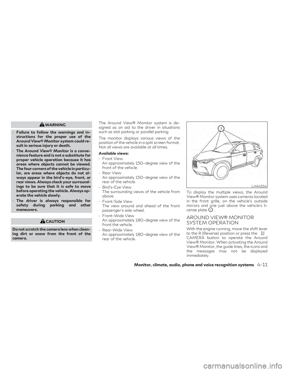
rear of the vehicle. To display the multiple views, the Around
View® Monitor system uses cameras located
in the front grille, on the vehicle’s outside
mirrors and one just above the vehicle’s li-
cense plate
O1.
AROUND VIEW® MONITOR
SYSTEM OPERATION
With the engine running, move the shift lever
to the R (Reverse) position or press the
CAMERA button to operate the Around
View® Monitor. When activating the Around
View® Monitor, the guide lines, the icons and
the messages may not be displayed
immediately.
LHA4554
Monitor, climate, audio, phone and voice recognition systems4-11
Page 210 of 542
When the camera is first activated with the
bird’s-eye view in the display, a red icon will
flash on the upper display. This indicates that
the sonar system is activated. For additional
information on the front and rear sonar sys-
tem, see “Front and rear sonar system”
(P. 5-160).
Available views
WARNING
• The distance guide lines and the vehicle
width lines should be used as a reference
only when the vehicle is on a paved, level
surface. The apparent distance viewed
on the monitor may be different than the
actual distance between the vehicle and
displayed objects.
• Use the displayed lines and the bird’s-
eye view as a reference. The lines and the
bird’s-eye view are greatly affected by
the number of occupants, cargo, fuel
level, vehicle position, road condition
and road grade.
• If the tires are replaced with different
sized tires, the predicted course lines and
the bird's-eye view may be displayed
incorrectly. •
When driving the vehicle up a hill, objects
viewed in the monitor are further than
they appear. When driving the vehicle
down a hill, objects viewed in the monitor
are closer than they appear.
• Objects in the rear view will appear visu-
ally opposite compared to when viewed
in the monitor and outside mirrors.
• Use the mirrors or actually look to prop-
erly judge distances to other objects.
• On a snow-covered or slippery road,
there may be a difference between the
predicted course lines and the actual
course line.
• The vehicle width and predicted course
lines are wider than the actual width and
course.
• The displayed lines will appear slightly
off to the right, because the rearview
camera is not installed in the rear center
of the vehicle.
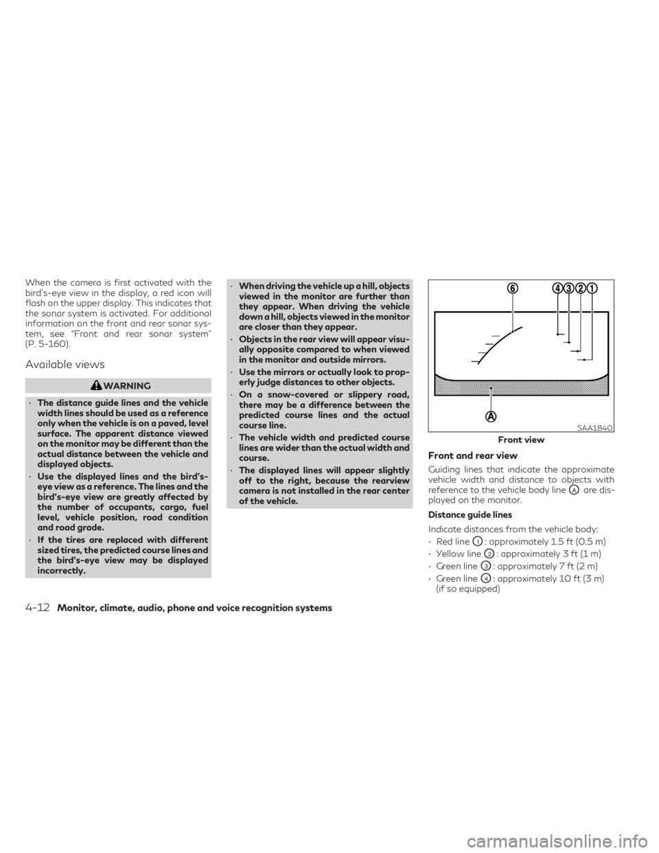
Front and rear view
Guiding lines that indicate the approximate
vehicle width and distance to objects with
reference to the vehicle body line
OAare dis-
played on the monitor.
Distance guide lines
Indicate distances from the vehicle body:
• Red line
O1: approximately 1.5 ft (0.5 m)
• Yellow line
O2: approximately 3 ft (1 m)
• Green line
O3: approximately 7 ft (2 m)
• Green line
O4: approximately 10 ft (3 m)
(if so equipped)
SAA1840
Front view
4-12Monitor, climate, audio, phone and voice recognition systems
Page 213 of 542
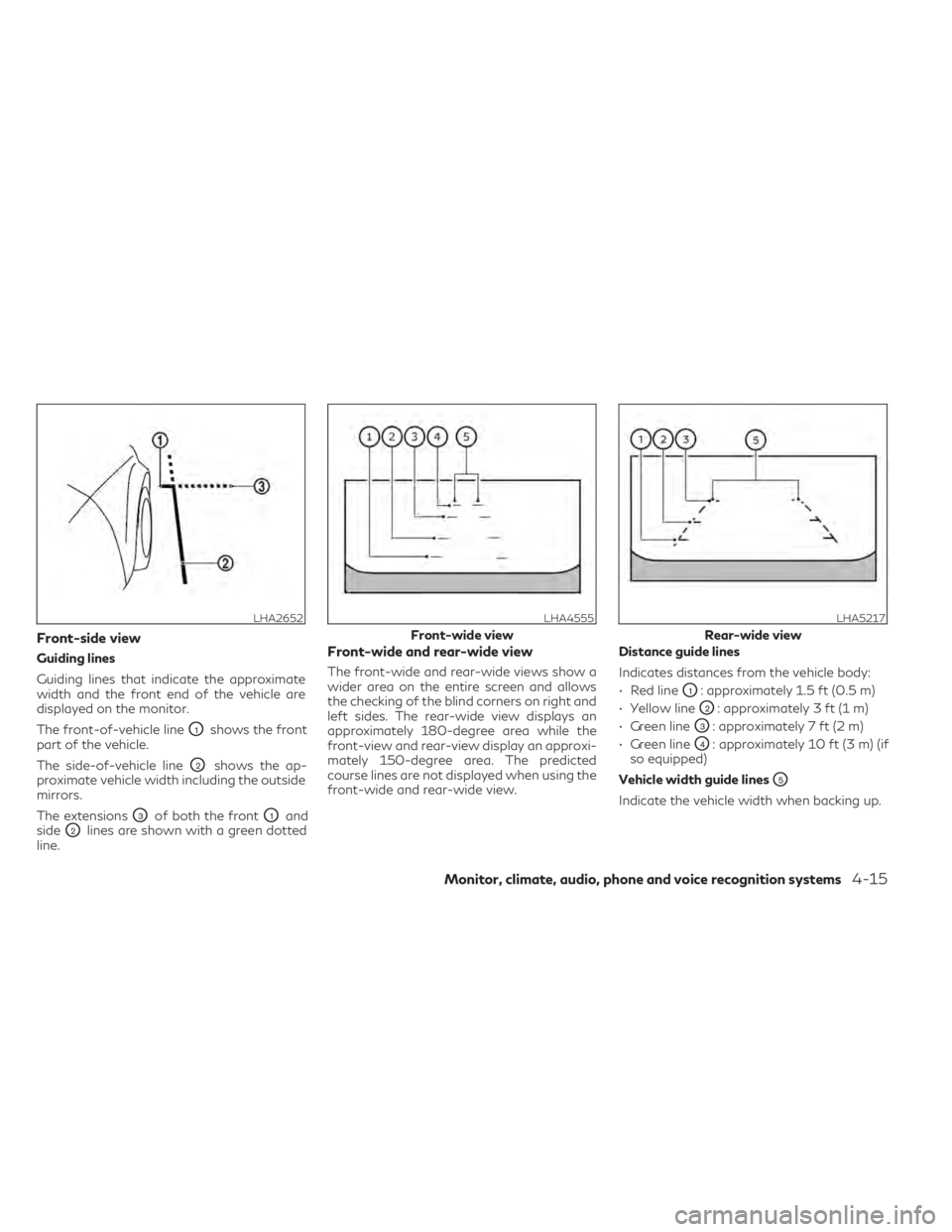
Front-side view
Guiding lines
Guiding lines that indicate the approximate
width and the front end of the vehicle are
displayed on the monitor.
The front-of-vehicle line
O1shows the front
part of the vehicle.
The side-of-vehicle line
O2shows the ap-
proximate vehicle width including the outside
mirrors.
The extensions
O3of both the frontO1and
side
O2lines are shown with a green dotted
line.
Front-wide and rear-wide view
The front-wide and rear-wide views show a
wider area on the entire screen and allows
the checking of the blind corners on right and
left sides. The rear-wide view displays an
approximately 180-degree area while the
front-view and rear-view display an approxi-
mately 150-degree area. The predicted
course lines are not displayed when using the
front-wide and rear-wide view. Distance guide lines
Indicates distances from the vehicle body:
• Red line
O1: approximately 1.5 ft (0.5 m)
• Yellow line
O2: approximately 3 ft (1 m)
• Green line
O3: approximately 7 ft (2 m)
• Green line
O4: approximately 10 ft (3 m) (if
so equipped)
Vehicle width guide lines
O5
Indicate the vehicle width when backing up.
LHA2652LHA4555
Front-wide view
LHA5217
Rear-wide view
Monitor, climate, audio, phone and voice recognition systems4-15