steering INFINITI QX50 2023 Owner's Guide
[x] Cancel search | Manufacturer: INFINITI, Model Year: 2023, Model line: QX50, Model: INFINITI QX50 2023Pages: 548, PDF Size: 6.17 MB
Page 206 of 548

1. Adjust the driver's seat, steering column(if so equipped), and outside mirrors to the
desired positions by manually operating
each adjusting switch. For additional in-
formation, see “Seats” (P. 1-2), “Steering
wheel” (P. 3-31) and “Outside mirrors”
(P. 3-35).
2. Push the SET switch and, within 5 sec- onds, push the memory switch (1 or 2).
The indicator light for the pushed memory
switch will come on and stay on for ap-
proximately 5 seconds.
The chime will sound when the memory is
stored.
NOTE:
If a new memory position is stored in the
same memory switch, the previous memory
position will be overwritten by the new
stored position.
Confirming memory storage
• Push the SET switch.
• If a memory position has been stored in the switch (1 or 2) then the indicator light for
the respective switch will stay on for ap-
proximately 5 seconds.
Linking log-in function to a stored
memory position
The log-in function can be linked to a stored
memory position with the following
procedure.
1. Place the ignition switch in the ON posi- tion while carrying the Intelligent Key that
was registered to the vehicle with a log-in
function.
NOTE:Make sure the Intelligent Keys are far apart.
Otherwise, the vehicle may detect the
wrong Intelligent Key.
2. Adjust the position of the driver’s seat, steering column (if so equipped) and out-
side mirrors. For additional information,
see “Seats” (P. 1-2), “Steering wheel”
(P. 3-31) and “Outside mirrors” (P. 3-35).
3. Place the ignition switch in the OFF position.
The next time you log in (selecting the user on
the display) after placing the ignition switch in
the ON position while carrying the Intelligent
Key, the system will automatically adjust to
the memorized driving position. For additional information, see “Log-in func-
tion” (P. 3-18) and the separate INFINITI In-
Touch™ Owner’s Manual.
ENTRY/EXIT FUNCTION
This system is designed so that the driver's
seat and steering column (if so equipped) will
automatically move when the vehicle is en-
gaged in the P (Park) position. This allows the
driver to easily get in and out of the driver’s
seat.
The driver’s seat will slide backward and the
steering column (if so equipped) will move up
when the ignition is switched to OFF and the
driver’s door is opened.
The driver’s seat and steering wheel will re-
turn to the previous position when the igni-
tion is switched to ON.
The entry/exit function can be adjusted or
canceled through the “Comfort & Conve-
nience” options of the “Settings” menu in the
lower touch-screen display by performing the
following:
• Switch the Lift Steering upon Exit from ON
to OFF.
• Switch the Slide Driver Seat Back on Exit from ON to OFF.
3-38Pre-driving checks and adjustments
Page 207 of 548

For additional information, refer to the sepa-
rate INFINITI InTouch® Owner’s Manual.
Restarting the entry/exit function
If the battery cable is disconnected, or if the
fuse opens, the stored memory positions will
be lost and some of the functions will be
restricted:
1. Drive the vehicle over 25 mph (40 km/h).
OR
2. Open and close the driver's door morethan two times with the ignition switch in
the OFF position.
The entry/exit function should now work
properly.
SETTING MEMORY FUNCTION
The position of the following settings can be
linked to the Intelligent Key and the memo-
rized settings can be available for each Intel-
ligent Key.
• Climate control system
• Navigation system
• Audio system To use the memory function, set the climate,
navigation and audio systems to the driver's
preferred settings. Lock the doors with the
Intelligent Key. Each Intelligent Key may be
set with the driver's individual preferences.
When a new Intelligent Key is used, “Connec-
tion with the key has been done” will be dis-
played on the vehicle information display and
the memorized settings are available.
To engage the memorized settings, perform
the following:
1. Carry the Intelligent Key that is linked to
the memorized settings.
2. Unlock the doors by pushing the driver’s door handle request switch or the
button on the Intelligent Key.
3. Place the ignition switch in the ON posi- tion. The settings linked to the Intelligent
Key will start.
For additional information on using the cli-
mate control system, see “Heater and air con-
ditioner (automatic)” (P. 4-35).
For additional information, see “Monitor, cli-
mate, audio, phone and voice recognition
systems” section of this manual or the sepa-
rate INFINITI InTouch® Owner’s Manual.
SYSTEM OPERATION
The memory seat system will not work or will
stop operating under the following conditions:
• When the vehicle speed is above 4 mph (7 km/h).
• When any of the memory switches are pushed while the memory seat system is
operating.
• When the switch for the driver’s seat and steering column (if so equipped) is pushed
while the memory seat system is operating.
• When the seat has already been moved to the memorized position.
• When no seat position is stored in the memory switch.
• When the shift position is moved from P (Park) to any other position.
The memory seat system can be adjusted and
canceled. It is recommended you visit an
INFINITI retailer for this service.
Pre-driving checks and adjustments3-39
Page 213 of 548
HOW TO READ THE DISPLAYED
LINES
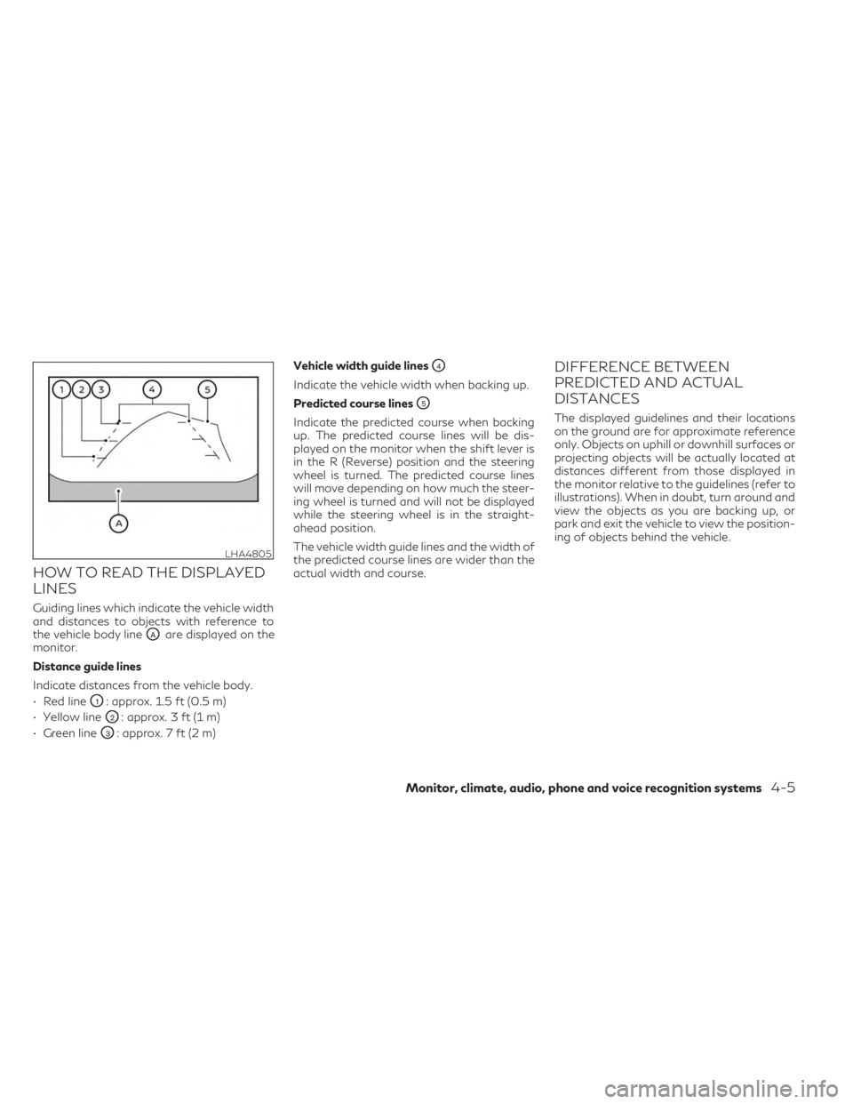
Guiding lines which indicate the vehicle width
and distances to objects with reference to
the vehicle body line
OAare displayed on the
monitor.
Distance guide lines
Indicate distances from the vehicle body.
• Red line
O1: approx. 1.5 ft (0.5 m)
• Yellow line
O2: approx. 3 ft (1 m)
• Green line
O3: approx. 7 ft (2 m) Vehicle width guide lines
O4
Indicate the vehicle width when backing up.
Predicted course lines
O5
Indicate the predicted course when backing
up. The predicted course lines will be dis-
played on the monitor when the shift lever is
in the R (Reverse) position and the steering
wheel is turned. The predicted course lines
will move depending on how much the steer-
ing wheel is turned and will not be displayed
while the steering wheel is in the straight-
ahead position.
The vehicle width guide lines and the width of
the predicted course lines are wider than the
actual width and course.
DIFFERENCE BETWEEN
PREDICTED AND ACTUAL
DISTANCES
The displayed guidelines and their locations
on the ground are for approximate reference
only. Objects on uphill or downhill surfaces or
projecting objects will be actually located at
distances different from those displayed in
the monitor relative to the guidelines (refer to
illustrations). When in doubt, turn around and
view the objects as you are backing up, or
park and exit the vehicle to view the position-
ing of objects behind the vehicle.
LHA4805
Monitor, climate, audio, phone and voice recognition systems4-5
Page 215 of 548
Backing up behind a projecting
object
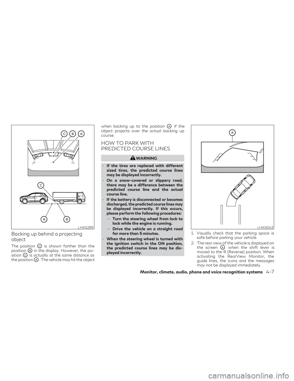
The positionOCis shown farther than the
position
OBin the display. However, the po-
sition
OCis actually at the same distance as
the position
OA. The vehicle may hit the object when backing up to the position
OAif the
object projects over the actual backing up
course.
HOW TO PARK WITH
PREDICTED COURSE LINES
WARNING
• If the tires are replaced with different
sized tires, the predicted course lines
may be displayed incorrectly.
• On a snow-covered or slippery road,
there may be a difference between the
predicted course line and the actual
course line.
•
If the battery is disconnected or becomes
discharged, the predicted course lines may
be displayed incorrectly. If this occurs,
please perform the following procedures:
– Turn the steering wheel from lock to
lock while the engine is running.
– Drive the vehicle on a straight road
for more than 5 minutes.
• When the steering wheel is turned with
the ignition switch in the ON position,
the predicted course lines may be dis-
played incorrectly. 1. Visually check that the parking space is
safe before parking your vehicle.
2. The rear view of the vehicle is displayed on the screen
OAwhen the shift lever is
moved to the R (Reverse) position. When
activating the RearView Monitor, the
guide lines, the icons and the messages
may not be displayed immediately.
LHA5289LHA5043
Monitor, climate, audio, phone and voice recognition systems4-7
Page 216 of 548
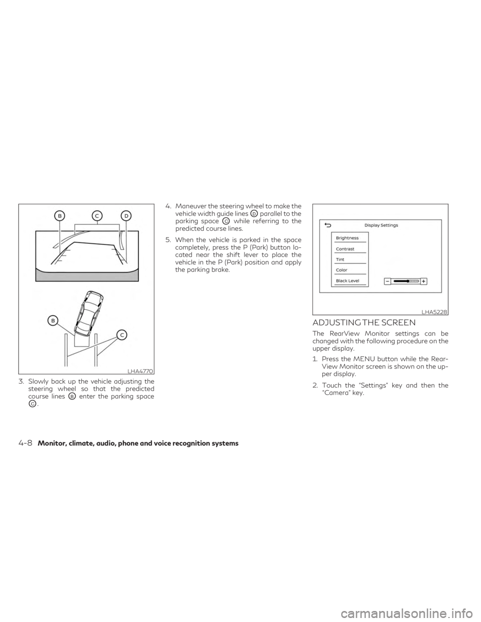
3. Slowly back up the vehicle adjusting thesteering wheel so that the predicted
course lines
OBenter the parking space
OC. 4. Maneuver the steering wheel to make the
vehicle width guide lines
ODparallel to the
parking space
OCwhile referring to the
predicted course lines.
5. When the vehicle is parked in the space completely, press the P (Park) button lo-
cated near the shift lever to place the
vehicle in the P (Park) position and apply
the parking brake.
ADJUSTING THE SCREEN
The RearView Monitor settings can be
changed with the following procedure on the
upper display.
1. Press the MENU button while the Rear-View Monitor screen is shown on the up-
per display.
2. Touch the “Settings” key and then the “Camera” key.
LHA4770
LHA5228
4-8Monitor, climate, audio, phone and voice recognition systems
Page 222 of 548
Front and rear view
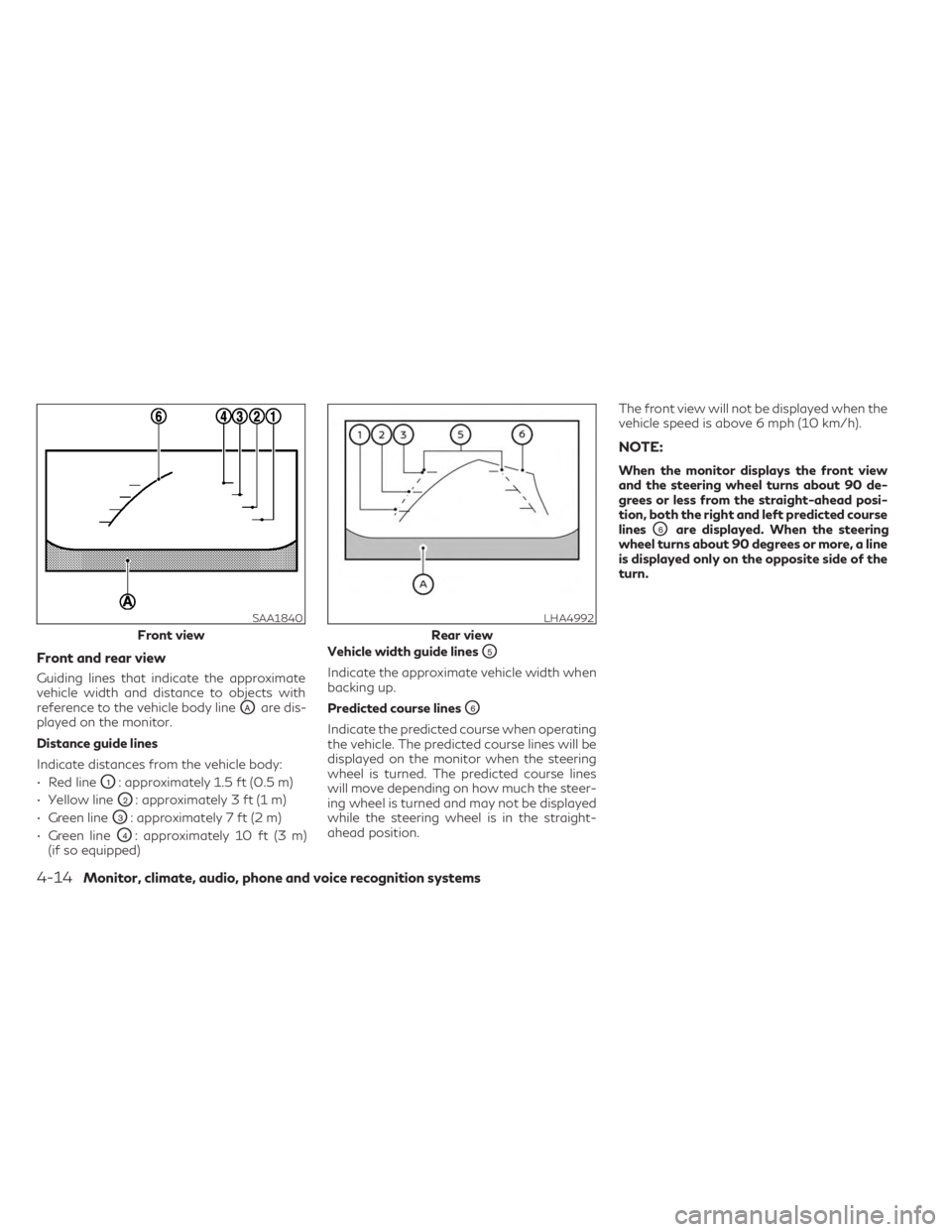
Guiding lines that indicate the approximate
vehicle width and distance to objects with
reference to the vehicle body line
OAare dis-
played on the monitor.
Distance guide lines
Indicate distances from the vehicle body:
• Red line
O1: approximately 1.5 ft (0.5 m)
• Yellow line
O2: approximately 3 ft (1 m)
• Green line
O3: approximately 7 ft (2 m)
• Green line
O4: approximately 10 ft (3 m)
(if so equipped) Vehicle width guide lines
O5
Indicate the approximate vehicle width when
backing up.
Predicted course lines
O6
Indicate the predicted course when operating
the vehicle. The predicted course lines will be
displayed on the monitor when the steering
wheel is turned. The predicted course lines
will move depending on how much the steer-
ing wheel is turned and may not be displayed
while the steering wheel is in the straight-
ahead position. The front view will not be displayed when the
vehicle speed is above 6 mph (10 km/h).
NOTE:
When the monitor displays the front view
and the steering wheel turns about 90 de-
grees or less from the straight-ahead posi-
tion, both the right and left predicted course
lines
O6are displayed. When the steering
wheel turns about 90 degrees or more, a line
is displayed only on the opposite side of the
turn.
SAA1840
Front view
LHA4992
Rear view
4-14Monitor, climate, audio, phone and voice recognition systems
Page 223 of 548
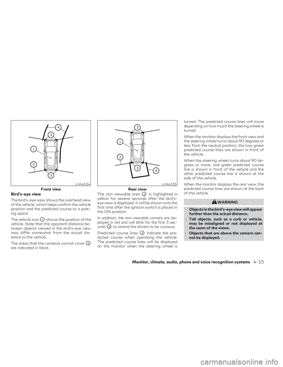
Bird’s-eye view
The bird's-eye view shows the overhead view
of the vehicle, which helps confirm the vehicle
position and the predicted course to a park-
ing space.
The vehicle icon
O1shows the position of the
vehicle. Note that the apparent distance be-
tween objects viewed in the bird's-eye view
may differ somewhat from the actual dis-
tance to the vehicle.
The areas that the cameras cannot cover
O2
are indicated in black. The non-viewable area
O2is highlighted in
yellow for several seconds after the bird’s-
eye view is displayed. It will be shown only the
first time after the ignition switch is placed in
the ON position.
In addition, the non-viewable corners are dis-
played in red and will blink for the first 3 sec-
onds
O3to remind the drivers to be cautious.
Predicted course linesO4indicate the pre-
dicted course when operating the vehicle.
The predicted course lines will be displayed
on the monitor when the steering wheel is turned. The predicted course lines will move
depending on how much the steering wheel is
turned.
When the monitor displays the front view and
the steering wheel turns about 90 degrees or
less from the neutral position, the two green
predicted course lines are shown in front of
the vehicle.
When the steering wheel turns about 90 de-
grees or more, one green predicted course
line is shown in front of the vehicle and the
other predicted course line is shown at the
side of the vehicle.
When the monitor displays the rear view, the
predicted course lines are shown at the back
of the vehicle.
WARNING
• Objects in the bird's-eye view will appear
further than the actual distance.
• Tall objects, such as a curb or vehicle,
may be misaligned or not displayed at
the seam of the views.
• Objects that are above the camera can-
not be displayed.
LHA4534
Front view
LHA4535
Rear view
Monitor, climate, audio, phone and voice recognition systems4-15
Page 227 of 548
when backing up to the positionOAif the
object projects over the actual backing up
course.
HOW TO PARK WITH
PREDICTED COURSE LINES
WARNING
• If the tires are replaced with different
sized tires, the predicted course lines
may be displayed incorrectly.
• On a snow-covered or slippery road,
there may be a difference between the
predicted course line and the actual
course line.
•
If the battery is disconnected or becomes
discharged, the predicted course lines may
be displayed incorrectly. If this occurs,
please perform the following procedures:
– Turn the steering wheel from lock to
lock while the engine is running.
– Drive the vehicle on a straight road
for more than 5 minutes.
• When the steering wheel is turned with
the ignition switch in the ON position,
the predicted course lines may be dis-
played incorrectly. 1. Visually check that the parking space is
safe before parking your vehicle.
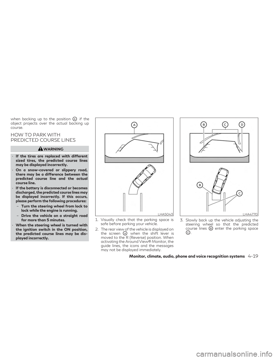
2. The rear view of the vehicle is displayed on the screen
OAwhen the shift lever is
moved to the R (Reverse) position. When
activating the Around View® Monitor, the
guide lines, the icons and the messages
may not be displayed immediately. 3. Slowly back up the vehicle adjusting the
steering wheel so that the predicted
course linesOBenter the parking space
OC.
LHA5043LHA4770
Monitor, climate, audio, phone and voice recognition systems4-19
Page 228 of 548
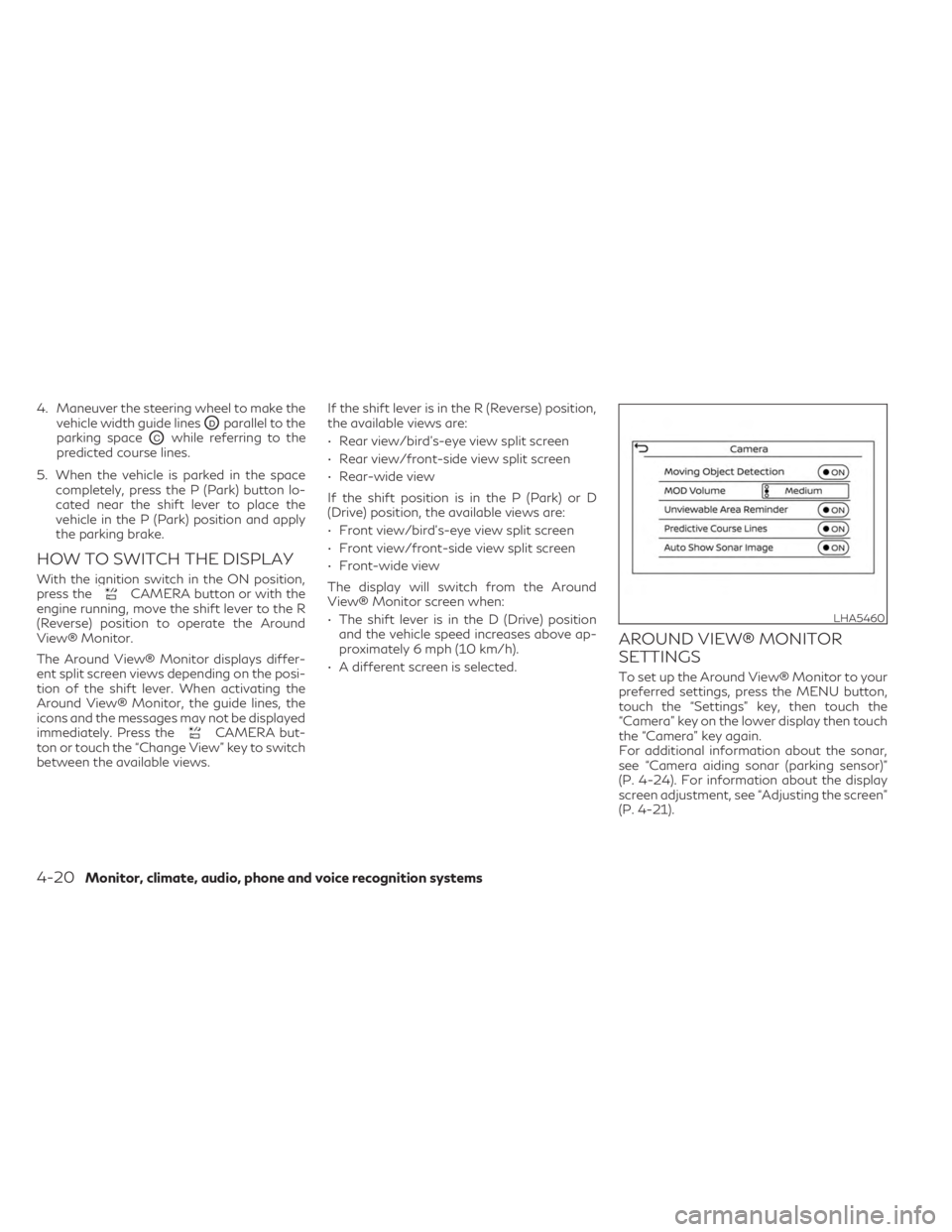
4. Maneuver the steering wheel to make thevehicle width guide lines
ODparallel to the
parking space
OCwhile referring to the
predicted course lines.
5. When the vehicle is parked in the space completely, press the P (Park) button lo-
cated near the shift lever to place the
vehicle in the P (Park) position and apply
the parking brake.
HOW TO SWITCH THE DISPLAY
With the ignition switch in the ON position,
press theCAMERA button or with the
engine running, move the shift lever to the R
(Reverse) position to operate the Around
View® Monitor.
The Around View® Monitor displays differ-
ent split screen views depending on the posi-
tion of the shift lever. When activating the
Around View® Monitor, the guide lines, the
icons and the messages may not be displayed
immediately. Press the
CAMERA but-
ton or touch the “Change View” key to switch
between the available views. If the shift lever is in the R (Reverse) position,
the available views are:
• Rear view/bird’s-eye view split screen
• Rear view/front-side view split screen
• Rear-wide view
If the shift position is in the P (Park) or D
(Drive) position, the available views are:
• Front view/bird’s-eye view split screen
• Front view/front-side view split screen
• Front-wide view
The display will switch from the Around
View® Monitor screen when:
• The shift lever is in the D (Drive) position
and the vehicle speed increases above ap-
proximately 6 mph (10 km/h).
• A different screen is selected.
AROUND VIEW® MONITOR
SETTINGS
To set up the Around View® Monitor to your
preferred settings, press the MENU button,
touch the “Settings” key, then touch the
“Camera” key on the lower display then touch
the “Camera” key again.
For additional information about the sonar,
see “Camera aiding sonar (parking sensor)”
(P. 4-24). For information about the display
screen adjustment, see “Adjusting the screen”
(P. 4-21).
LHA5460
4-20Monitor, climate, audio, phone and voice recognition systems
Page 244 of 548

Start the engine and operate the controls to
activate the air conditioner.
NOTE:
• Odors from inside and outside the vehiclecan build up in the air conditioner unit.
Odor can enter the passenger compart-
ment through the vents.
• When parking, set the heater and air con- ditioner controls to turn off air recircula-
tion to allow fresh air into the passenger
compartment. This should help reduce
odors inside the vehicle
AUTOMATIC OPERATION
Press the AUTO button to set the automatic
control mode that keeps the air distribution,
temperature and the fan speed auto-
matically.
Cooling and/or dehumidified
heating (AUTO)
This mode may be used all year round as the
system automatically works to keep a con-
stant temperature. Air flow distribution, air
intake control, and fan speed are also con-
trolled automatically.
1. Press the
CLIMATE button on the
lower display menu. The CLIMATE screen
will display on the lower display. 2. Press the AUTO button on. (The indicator
on the button will illuminate and AUTO
will be displayed on the CLIMATE screen.)
3. Press the
temperature control
buttons on the driver’s side to set the de-
sired temperature.
• The temperature of the passenger com- partment will be maintained automatically.
Air flow distribution, air intake control and
fan speed are also controlled automatically.
• A visible mist may be seen coming from the vents in hot, humid conditions as the air is
cooled rapidly. This does not indicate a
malfunction.
Dehumidified defrosting or
defogging
1. Press thefront defroster button on.
(The indicator light on the button will
come on.)
2. Operate the
temperature con-
trol buttons to set the desired
temperature.
• To quickly remove ice from the outside of the windows, use the
fan speed con-
trol button or the “” key to set the fan
speed to maximum. • As soon as possible after the windshield is
clean, press the AUTO button to return to
the automatic mode.
•
When thefront defroster button is
pressed, the air conditioner will automatically
be turned on at outside temperatures ap-
proximately 32°F (0°C) to defog the wind-
shield. The air recirculate mode automatically
turns off, allowing outside air to be drawn
into the passenger compartment to further
improve the defogging performance.
Remote Engine Start with
Intelligent Climate Control (if so
equipped)
Vehicles equipped with automatic climate con-
trols and Remote Engine Start function may go
into automatic heating or cooling mode when
Remote Engine Start is activated depending on
outside and cabin temperatures. During this
period, the climate control display and buttons
will be inoperable until the ignition switch is
placed in the ON position. In Remote Engine
Start defrosting mode, the rear window de-
froster, heated seat (if so equipped) and heated
steering wheel (if so equipped) may be acti-
vated automatically. In Remote Engine Start
cooling mode, the climate controlled seat (if so
equipped) may be activated automatically.
4-36Monitor, climate, audio, phone and voice recognition systems