change wheel INFINITI QX50 2023 Owners Manual
[x] Cancel search | Manufacturer: INFINITI, Model Year: 2023, Model line: QX50, Model: INFINITI QX50 2023Pages: 548, PDF Size: 6.17 MB
Page 4 of 548

For descriptions specified for all-wheel drive
models, anAWDmark is placed at the begin-
ning of the applicable sections/items.
As with other vehicles with features for off-
road use, failure to operate all-wheel drive
models correctly may result in loss of control
or an accident. For additional information,
see “Driving safety precautions” (P. 5-10).
ON-PAVEMENT AND OFF-ROAD DRIVING
This vehicle will handle and maneuver dif-
ferently from an ordinary passenger car
because it has a higher center of gravity for
off-road use. As with other vehicles with
features of this type, failure to operate this
vehicle correctly may result in loss of con-
trol or an accident.
For additional information, see “On- pave-
ment and off-road driving precautions”
(P. 5-8), “Avoiding collision and roll- over”
(P. 5-8) and “Driving safety precautions”
(P. 5-10).
MODIFICATION OF YOUR VEHICLE
This vehicle should not be modified. Modi-
fication could affect its performance,
safety, emissions or durability and may
even violate governmental regulations. In
addition, damage or performance problems
resulting from modifications may not be
covered under INFINITI warranties.
WARNING
Installing an aftermarket On-Board Diag-
nostic (OBD) plug-in device that uses the
port during normal driving, for example
remote insurance company monitoring,
remote vehicle diagnostics, telematics or
engine reprogramming, may cause inter-
ference or damage to vehicle systems. We
do not recommend or endorse the use of
any aftermarket OBD plug-in devices, un-
less specifically approved by INFINITI. The
vehicle warranty may not cover damage
caused by any aftermarket plug-in device. This manual includes information for all fea-
tures and equipment available on this model.
Features and equipment in your vehicle may
vary depending on model, trim level, options
selected, order, date of production, region or
availability. Therefore, you may find informa-
tion about features or equipment that are not
included or installed on your vehicle.
All information, specifications and illustra-
tions in this manual are those in effect at the
time of printing. INFINITI reserves the right
to change specifications, performance, de-
sign or component suppliers without notice
and without obligation. From time to time,
INFINITI may update or revise this manual to
provide Owners with the most accurate in-
formation currently available. Please care-
fully read and retain with this manual all revi-
sion updates sent to you by INFINITI to
ensure you have access to accurate and up-
to-date information regarding your vehicle.
Current versions of vehicle Owner's Manuals
and any updates can also be found in the
Owner section of the INFINITI website at
https://owners.infinitiusa.com/iowners/
navigation/manualsAndGuides. If you have
questions concerning any information in your
Owner's Manual, contact INFINITI Con-
sumer Affairs. See the INFINITI CUSTOMER
CARE PROGRAM page in this Owner’s
Manual for contact information.
WHEN READING THE MANUAL
Page 74 of 548

• An object placed under the front passengerseat.
• An object placed between the seat cushion and center console.
If the vehicle is moving, please come to a stop
when it is safe to do so. Check and correct
any of the above conditions. Restart the ve-
hicle and wait 1 minute.
NOTE:
A system check will be performed during
which the front passenger air bag status light
will remain lit for about 7 seconds initially.
If the light is still OFF after this, the small
adult, child or child restraint should be repo-
sitioned in the rear seat and the vehicle
should be checked as soon as possible. It is
recommended that you visit an INFINITI re-
tailer for this service.
3. If the light is OFF with no front passenger and no objects on the front passenger
seat, the vehicle should be checked. It is
recommended that you visit an INFINITI
retailer as soon as possible.
Other supplemental front-impact air bag
precautions
WARNING
• Do not place any objects on the steering
wheel pad or on the instrument panel.
Also, do not place any objects between
any occupant and the steering wheel
or instrument panel. Such objects may
become dangerous projectiles and cause
injury if the front air bags inflate.
• Immediately after inflation, several
front air bag system components will be
hot. Do not touch them; you may se-
verely burn yourself.
• No unauthorized changes should be
made to any components or wiring of
the supplemental air bag system. This is
to prevent accidental inflation of the
supplemental air bag or damage to the
supplemental air bag system.
• Do not make unauthorized changes to
your vehicle's electrical system, suspen-
sion system or front end structure. This
could affect proper operation of the
front air bag system. •
Tampering with the front air bag system
may result in serious personal injury.
Tampering includes changes to the
steering wheel and the instrument panel
assembly by placing material over the
steering wheel pad and above the instru-
ment panel or by installing additional
trim material around the air bag system.
• Removing or modifying the front pas-
senger seat may affect the function of
the air bag system and result in serious
personal injury.
• Modifying or tampering with the front
passenger seat may result in serious per-
sonal injury. For example, do not change
the front seats by placing material on
the seat cushion or by installing addi-
tional trim material, such as seat covers,
on the seat that are not specifically
designed to assure proper air bag opera-
tion. Additionally, do not stow any ob-
jects under the front passenger seat
or the seat cushion and seatback. Such
objects may interfere with the proper
operation of the occupant classification
sensor (weight sensor).
1-56Safety-Seats, seat belts and supplemental restraint system
Page 107 of 548
When the “Tire Pressure Low — Add Air” or
“Flat Tire — Visit dealer” warning appears, the
display can be switched to the tire pressure
mode by pushing the
orswitch to
reveal additional details on the displayed
warning.
For additional information, see “Low tire pres-
sure warning light” (P. 2-14), “Tire Pressure
Monitoring System (TPMS)” (P. 5-5), “Flat tire”
(P. 6-3) and “Types of tires” (P. 8-35)
8. Chassis Control
This mode shows the operating condition of
the following systems:
• Hill start assist system
• Automatic brake hold function
• Active Trace Control system
• Active Engine Brake system
• Active Ride Control system
For additional information, see “Chassis Con-
trol” (P. 5-144).
9. Oil control system
Engine oil information informs the distance
to oil change. Never exceed one year or 7500
miles (12000 km) between oil change inter-
vals. For additional information, see “Oil con-
trol system” (P. 2-24).
10. Variable Compression Turbo
This is not a physical gauge. It is a display
option in the vehicle information display that
can be selected. For additional information,
see “Variable Compression Turbo” (P. 2-8).
11. ProPILOT Assist
The ProPILOT Assist mode shows operating
conditions for the following systems:
• Intelligent Cruise Control (ICC)
• Steering Assist
The display will also be shown when the Pro-
PILOT Assist is turned on. For additional in-
formation, see “ProPILOT Assist” (P. 5-73).
12. Traffic Sign Recognition (if so
equipped)
The Traffic Sign Recognition (TSR) system
provides the driver with information about
the most recently detected speed limit.
For additional information, see “Traffic Sign
Recognition (TSR) (P. 5-32).
13. Compass
This display indicates the direction the vehicle
is heading.
RESETTING THE TRIP
COMPUTER
1. Press thebutton until you reach the
trip computer mode.
2. Press the
button again for more
than 1.5 seconds to reset average fuel
consumption, average speed, distance to
empty, and journey time.
TIRE PRESSURE INFORMATION
(Display Settings)
The tire pressure mode shows the pressure of
all four tires while the vehicle is driven.
When the “Tire Pressure Low-Add Air” or
“Flat Tire-Visit dealer” (if so equipped)
warning appears, the display can be switched
to the tire pressure mode by pushing the
orswitch on the steering wheel.
The tire pressure unit can be changed in the
lower display.
1. Touch the “Settings” key.
2. Select “Meter” and then select “TPMS settings”.
For additional information, refer to the sepa-
rate INFINITI InTouch® Owner’s Manual.
Instruments and controls2-23
Page 108 of 548
NOTE:
After the ignition switch is placed in the ON
position, it may take a period of time for
the tire pressure to be displayed while the
vehicle is driven. Depending on the radio
wave circumstance, tire pressure may not
correctly be displayed.
OIL CONTROL SYSTEM
Engine oil information informs the distance
to oil change. Never exceed one year or 7500
miles (12000 km) between oil change
intervals.
Display when
ignition is ONDisplay timing Action Required
Engine Oil
Service due in
xxx miles Remaining oil
life is less than
940 miles
(1500 km). Plan to have
your vehicle
serviced.
Engine Oil
Service due Remaining oil
life is 0 miles
(0 km). Have your
vehicle serviced
within two
weeks or less
than 500 miles
(800 km).
The oil change interval cannot be adjusted
manually. The distance to oil change interval is calcu-
lated depending on the driving conditions and
set automatically by the oil control system.
CAUTION
If the oil replacement indicator is displayed,
change the engine oil within two weeks or
less than 500 miles (800 km).
Operating the vehicle with deteriorated oil
can damage the engine.
To reset oil control system:
1. Place the ignition switch in the “ON” position.
2. Push the trip computer switches
andlocated on the right side of the steer-
ing wheel to change the display.
3. Select the Engine Oil Service due in xxx miles display.
4. Push and hold the
orswitch for
longer than 1 second. Hold until the re-
maining distance changes to – – – miles
(km).
VEHICLE INFORMATION
DISPLAY WARNINGS AND
INDICATORS
The following messages may appear in your
vehicle information display.
Engine start operation for
Intelligent Key system
(if I-Key battery level is low)
This indicator appears when the battery of
the Intelligent Key is low and when the Intel-
ligent Key system and the vehicle are not
communicating normally.
If this appears, touch the ignition switch
with the Intelligent Key while depressing the
brake pedal. For additional information, see
“INFINITI Intelligent Key battery discharge”
(P. 8-22).
Key Battery Low
This indicator appears when the Intelligent
Key battery is running out of power.
If this indicator appears, replace the battery
with a new one. For additional information,
see “Battery replacement” (P. 8-22).
2-24Instruments and controls
Page 113 of 548

AWD High Temp. Stop vehicle
This warning may appear while trying to free
a stuck vehicle due to increased oil tempera-
ture. The driving mode may change to
2-Wheel Drive (2WD). If this warning is dis-
played, stop the vehicle with the engine idling,
as soon as it is safe to do so. Then if the
warning turns off, you can continue driving.
AWD Tire Size Incorrect: See
Owner’s Manual
This warning may appear if there is a large
difference between the diameters of the
front and rear wheels. Pull off the road in a
safe area, with the engine idling. Check that
all the tire sizes are the same, that the tire
pressure is correct and that the tires are not
excessively worn.
CVT (AT) Malfunction Service now
This warning appears when there is a prob-
lem with the CVT system. If this warning
comes on, have the system checked. It is rec-
ommended that you visit an INFINITI retailer
for this service.
CVT (AT) hot Power reduced
This transmission has a high fluid tempera-
ture protection mode. If the fluid temperature
becomes too high (for example, climbing
steep grades in high temperatures with heavy
loads, such as when towing a trailer), engine
power and, under some conditions, vehicle
speed will be decreased automatically to re-
duce the chance of transmission damage.
Vehicle speed can be controlled with the ac-
celerator pedal, but the engine and vehicle
speed may be reduced.
WARNING
When the high fluid temperature protec-
tion mode operation occurs, vehicle speed
may be gradually reduced. The reduced
speed may be lower than other traffic,
which could increase the chance of a colli-
sion. Be especially careful when driving. If
necessary, pull to the side of the road at a
safe place and allow the transmission to
return to normal operation; or have it re-
paired if necessary.
Engine hot Power reduced
This engine has a high fluid temperature pro-
tection mode. If the fluid temperature be-
comes too high (for example, climbing steep
grades in high temperatures with heavy
loads, such as when towing a trailer), engine
power and, under some conditions, vehicle
speed will be decreased automatically to re-
duce the chance of engine damage. Vehicle
speed can be controlled with the accelerator
pedal, but the engine and vehicle speed may
be reduced.
WARNING
When the high fluid temperature protec-
tion mode operation occurs, vehicle speed
may be gradually reduced. The reduced
speed may be lower than other traffic,
which could increase the chance of a colli-
sion. Be especially careful when driving. If
necessary, pull to the side of the road at a
safe place and allow the engine to return to
normal operation; or have it repaired if
necessary.
Instruments and controls2-29
Page 127 of 548

•The timing of switching the low beam
and high beam may change under the fol-
lowing situations.
–
The brightness of the headlights of the
oncoming vehicle or leading vehicle.
–The movement and direction of the on-
coming vehicle and the leading vehicle.
– When only one light on the oncoming
vehicle or the leading vehicle is
illuminated.
– When the oncoming vehicle or the
leading vehicle is a two-wheeled
vehicle.
– Road conditions (incline, curve, the
road surface, etc.).
– The number of passengers and the
amount of luggage.
High Beam Assist operation
To activate the High Beam Assist system,
turn the headlight switch to the AUTO posi-
tion
O1and push the lever forwardO2(high
beam position). The High Beam Assist indica-
tor light in the meter will illuminate while the
headlights are turned on. If the High Beam Assist indicator light does
not illuminate in the above condition, it may
indicate that the system is not functioning
properly. Have the system checked. It is rec-
ommended that you visit an INFINITI retailer
for this service.
When the vehicle speed lowers to less than
approximately 16 mph (25 km/h), the head-
light uses the low beam.
LIC3819
Type A (if so equipped)
LIC4756
Type B (if so equipped)
Instruments and controls2-43
Page 216 of 548
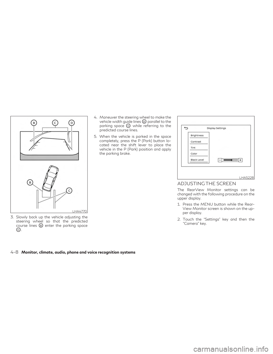
3. Slowly back up the vehicle adjusting thesteering wheel so that the predicted
course lines
OBenter the parking space
OC. 4. Maneuver the steering wheel to make the
vehicle width guide lines
ODparallel to the
parking space
OCwhile referring to the
predicted course lines.
5. When the vehicle is parked in the space completely, press the P (Park) button lo-
cated near the shift lever to place the
vehicle in the P (Park) position and apply
the parking brake.
ADJUSTING THE SCREEN
The RearView Monitor settings can be
changed with the following procedure on the
upper display.
1. Press the MENU button while the Rear-View Monitor screen is shown on the up-
per display.
2. Touch the “Settings” key and then the “Camera” key.
LHA4770
LHA5228
4-8Monitor, climate, audio, phone and voice recognition systems
Page 228 of 548
4. Maneuver the steering wheel to make thevehicle width guide lines
ODparallel to the
parking space
OCwhile referring to the
predicted course lines.
5. When the vehicle is parked in the space completely, press the P (Park) button lo-
cated near the shift lever to place the
vehicle in the P (Park) position and apply
the parking brake.
HOW TO SWITCH THE DISPLAY
With the ignition switch in the ON position,
press theCAMERA button or with the
engine running, move the shift lever to the R
(Reverse) position to operate the Around
View® Monitor.
The Around View® Monitor displays differ-
ent split screen views depending on the posi-
tion of the shift lever. When activating the
Around View® Monitor, the guide lines, the
icons and the messages may not be displayed
immediately. Press the
CAMERA but-
ton or touch the “Change View” key to switch
between the available views. If the shift lever is in the R (Reverse) position,
the available views are:
• Rear view/bird’s-eye view split screen
• Rear view/front-side view split screen
• Rear-wide view
If the shift position is in the P (Park) or D
(Drive) position, the available views are:
• Front view/bird’s-eye view split screen
• Front view/front-side view split screen
• Front-wide view
The display will switch from the Around
View® Monitor screen when:
• The shift lever is in the D (Drive) position
and the vehicle speed increases above ap-
proximately 6 mph (10 km/h).
• A different screen is selected.
AROUND VIEW® MONITOR
SETTINGS
To set up the Around View® Monitor to your
preferred settings, press the MENU button,
touch the “Settings” key, then touch the
“Camera” key on the lower display then touch
the “Camera” key again.
For additional information about the sonar,
see “Camera aiding sonar (parking sensor)”
(P. 4-24). For information about the display
screen adjustment, see “Adjusting the screen”
(P. 4-21).
LHA5460
4-20Monitor, climate, audio, phone and voice recognition systems
Page 248 of 548

Sync mode setting
The driver’s, passenger’s and rear (if so
equipped) temperature setpoints can be syn-
chronized using the “
SYNC” key on the
lower display. When the key is touched, tem-
perature settings become synchronized and
the SYNC indicator turns on.
• If the driver’s side temperature buttons are pressed, the driver’s side, passenger’s side,
and rear (if so equipped) temperature set-
tings will update simultaneously.
•
If the passenger’s side or rear (if so equipped)
temperature buttons are pressed, Sync mode
will exit, the indicator light will go off, and the
temperature will update based on the button
pressed. Driver’s side temperature will re-
main the same until manually changed.
Steering wheel heater (if so
equipped)
The heated steering wheel system is de-
signed to operate only when the surface tem-
perature of the steering wheel is below 68°F
(20°C).
If the surface temperature of the steering
wheel is below 68°F (20°C), the system will
heat the steering wheel and cycle off and
on to maintain a temperature above 68°F (20°C). The indicator light will remain on as
long as the system is on.
Touch the “
Steering Heater” key on the
CLIMATE screen on the lower display to turn
the steering wheel heater on or off. When the
steering wheel heater is on, the indicator light
is on.
NOTE:
• Once activated, your heated steering
wheel will automatically turn on and off to
maintain a temperature above 68°F
(20°C). The heated steering wheel will turn
off automatically after 30 minutes of use.
• When the temperature of the steering
wheel is above 122°F (50°C) and the
heated steering wheel is turned on, the
system will not heat the steering wheel.
This does not indicate a malfunction.
Automatic Climate Control System
(if so equipped)
The Automatic Climate Control System
keeps the air inside of the vehicle clean, using
the automatic air recirculation control with
the exhaust gas/outside odor detecting sen-
sor with ion control.
O1“Auto Recirc” key
Touch to turn on the automatic recirculation
mode.
O2Plasmacluster® icon
Indicates the Plasmacluster® ion emission
status.
Ion control:
The Automatic Climate Control System unit
generates highly concentrated Plasmaclus-
ter® ions into the air blown from the ventila-
tors to reduce odor absorbed into the interior
LHA5458
4-40Monitor, climate, audio, phone and voice recognition systems
Page 250 of 548

Press theto decrease the rear
temperature.
If front passengers touch the “
SYNC”
key on the Climate screen, the rear tempera-
ture settings will synchronize with the driver’s
and passenger’s side settings.
Heated 2nd row seat switches
(if so equipped)
For additional information, see “Heated 2nd
row seat switches” (P. 2-50).
Heater and air conditioner settings can be
changed on the screen.
1. Press the
MENU button on the
lower display menu.
2. Using the arrow, tab over to the next screen and touch the “Settings” key.
Touch the arrow again to get to the next
screen and touch “Others”.
3. Touch the “CLIMATE” key.
Available setting items may vary depending
on models and specifications. Available settings
•
Use A/C While Idle (if so equipped)
Touch to turn on/off the Idling Stop Prior-
ity mode. While this item is turned on and
the engine is on, the Climate Control will
not be affected by the Idling Stop activa-
tion. Otherwise, when the engine is off by
the Idle Stop function, the Climate Control
System will be able to heat and cool the
cabin.
• Steering Wheel Heater
Touch to turn the steering wheel heater on
and off.
• Auto Steering Wheel Heater
The automatic control mode for the
steering-wheel heating can be turned on
and off. When the item is turned on, the
steering-wheel heating will turn on auto-
matically if the temperature inside the ve-
hicle compartment is low at the time when
the ignition switch is placed in the ON
position. Regardless of the temperature,
the steering-wheel heating will turn off
after 30 minutes. If the steering-wheel
heater is turned on or off manually by
touching
on the CLIMATE screen,
the automatic steering-wheel heating
control mode will be canceled and will re-
turn to the manual mode.
LHA5459
HEATER AND AIR CONDITIONER
SETTINGS (if so equipped)
4-42Monitor, climate, audio, phone and voice recognition systems