ABS INFINITI QX56 2006 Factory Repair Manual
[x] Cancel search | Manufacturer: INFINITI, Model Year: 2006, Model line: QX56, Model: INFINITI QX56 2006Pages: 3383, PDF Size: 51.76 MB
Page 1069 of 3383

BRC-42
[VDC/TCS/ABS]
TROUBLE DIAGNOSIS FOR SELF-DIAGNOSTIC ITEMS
Revision: November 20092006 QX56
3. YAW RATE/SIDE/DECEL G SENSOR HARNESS INSPECTION
1. Turn off the ignition switch and disconnect yaw rate/side/decel G sensor connector M108 and ABS actua- tor and electric unit (control unit) connector E125.
2. Check continuity between the ABS actuator and electric unit (control unit) connector E125 and the yaw rate/side/decel G sensor connector M108.
OK or NG
OK >> GO TO 4.
NG >> Repair or replace as necessary.
4. YAW RATE/SIDE/DECEL G SENSOR INSPECTION
1. Connect the yaw rate/side/decel G sensor connector M108 and ABS actuator and electric unit (control unit) connector E125.
2. Use “DATA MONITOR ” to check if the yaw rate/side/decel G sensor signals are normal.
OK or NG
OK >> Inspection End.
NG >> Replace the yaw rate/side/decel G sensor. Refer to BRC-69, "
Removal and Installation" .
ABS actuator and electric unit
(control unit) harness connector E125 Yaw rate/side/decel G sensor
harness connector M108 Continuity
63 Ye s
24
5
25 1
29 2
Vehicle statusYaw ra te s en sor
(Data monitor standard) Side G sensor
(Data monitor standard) Decel G Sensor
(Data monitor standard)
When stopped -4 to +4 deg/s -1.1 to +1.1 m/s-0.11 G to +0.11 G
Right turn Negative value Negative value -
Left turn Positive value Positive value -
Speed up - -Negative value
Speed down --Positive value
Page 1070 of 3383
TROUBLE DIAGNOSIS FOR SELF-DIAGNOSTIC ITEMSBRC-43
[VDC/TCS/ABS]
C
DE
G H
I
J
K L
M A
B
BRC
Revision: November 2009 2006 QX56
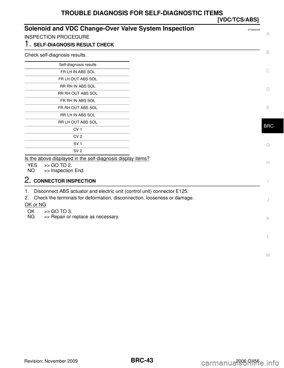
Solenoid and VDC Change-Over Valve System InspectionEFS004XW
INSPECTION PROCEDURE
1. SELF-DIAGNOSIS RESULT CHECK
Check self-diagnosis results.
Is the above displayed in the self-diagnosis display items?
YES >> GO TO 2.
NO >> Inspection End.
2. CONNECTOR INSPECTION
1. Disconnect ABS actuator and electric unit (control unit) connector E125.
2. Check the terminals for deformation, disconnection, looseness or damage.
OK or NG
OK >> GO TO 3.
NG >> Repair or replace as necessary.
Self-diagnosis results FR LH IN ABS SOL
FR LH OUT ABS SOL RR RH IN ABS SOL
RR RH OUT ABS SOL FR RH IN ABS SOL
FR RH OUT ABS SOL RR LH IN ABS SOL
RR LH OUT ABS SOL CV 1
CV 2SV 1
SV 2
Page 1071 of 3383

BRC-44
[VDC/TCS/ABS]
TROUBLE DIAGNOSIS FOR SELF-DIAGNOSTIC ITEMS
Revision: November 20092006 QX56
3. CHECKING SOLENOID POWER AND GROUND
1. Check voltage between ABS actuator and electric unit (control unit) harness connector E125 and body ground.
2. Check resistance between ABS actuator and electric unit (con- trol unit) harness connector E125 and body ground.
OK or NG
OK >> Perform self-diagnosis again. If the same results appear, replace ABS actuator and electric unit (control
unit). Refer to BRC-66, "
Removal and Installation" .
NG >> Repair the circuit.
Actuator Motor, Motor Relay, and Circuit InspectionEFS004XX
INSPECTION PROCEDURE
1. CHECKING SELF-DIAGNOSIS RESULTS
Check self-diagnosis results.
Is the above displayed in the self-diagnosis display items?
YES >> GO TO 2.
NO >> Inspection End.
2. CONNECTOR INSPECTION
1. Disconnect ABS actuator and electric unit (control unit) connector E125.
2. Check the terminals for deformation, disconnection, looseness or damage.
OK or NG
OK >> GO TO 3.
NG >> Repair or replace as necessary. ABS actuator and electric
unit (control unit)connector E125 Body
ground Measured
value
(Approx.)
32 — 12V
WFIA0195E
ABS actuator and electric unit (control unit)connector E125 Body
ground Measured
value Ω
(Approx.)
16 —0Ω
47 —0Ω
WFIA0196E
Self-diagnosis results
PUMP MOTOR
ACTUATOR RLY
Page 1072 of 3383

TROUBLE DIAGNOSIS FOR SELF-DIAGNOSTIC ITEMSBRC-45
[VDC/TCS/ABS]
C
DE
G H
I
J
K L
M A
B
BRC
Revision: November 2009 2006 QX56
3. CHECKING ABS MOTOR AND MOTOR RELAY POWER SYSTEM
1. Check voltage between ABS actuator and electric unit (control unit) harness connector E125 and body ground.
2. Check resistance between ABS actuator and electric unit (con- trol unit) connector E125 and body ground.
OK or NG
OK >> Perform self-diagnosis again. If the same results appear, replace ABS actuator and electric unit (control
unit). Refer to BRC-66, "
Removal and Installation" .
NG >> Repair the circuit.
Stop Lamp Switch System InspectionEFS004XY
INSPECTION PROCEDURE
1. SELF-DIAGNOSIS RESULT CHECK
Check self-diagnosis results.
Is the above displayed in the self-diagnosis display items?
YES >> GO TO 2.
NO >> Inspection End.
2. CONNECTOR INSPECTION
1. Disconnect the ABS actuator and electric unit (control unit) connector E125 and stop lamp switch connec- tor E38.
2. Check the terminals for deformation, disconnection, looseness or damage.
OK or NG
OK >> GO TO 3.
NG >> Repair or replace as necessary. ABS actuator and electric
unit (control unit)connector E125 Body
ground Measured
value
(Approx.)
1—1 2V
WFIA0209E
ABS actuator and electric
unit (control unit)
harness connector E125 Body
ground Measured
value Ω
(Approx.)
16 —0Ω
47 —0Ω
WFIA0196E
Self-diagnosis results
STOP LAMP SW
Page 1073 of 3383

BRC-46
[VDC/TCS/ABS]
TROUBLE DIAGNOSIS FOR SELF-DIAGNOSTIC ITEMS
Revision: November 20092006 QX56
3. STOP LAMP SWITCH INSPECTION
Check the voltage between the ABS actuator and electric unit (con-
trol unit) harness connector E125 terminal 41 and body ground.
OK or NG
OK >> Perform self-diagnosis again. If the same results appear, replace ABS actuator and electric unit (control
unit). Refer to BRC-66, "
Removal and Installation" .
NG >> GO TO 4.
4. STOP LAMP RELAY CIRCUIT INSPECTION
1. Disconnect the stop lamp relay harness connector E12.
2. Check the continuity between the ABS actuator and electric unit (control unit) harness connector E125 (B) terminal 41 and stop
lamp relay harness connector E12 (A) terminal 4.
OK or NG
OK >> Perform self-diagnosis again. If the same results appear, replace ABS actuator and electric unit (control
unit). Refer to BRC-66, "
Removal and Installation" .
NG >> Refer to LT- 1 0 6 , "
STOP LAMP" .
ABS/TCS/VDC Control Unit Power and Ground Systems InspectionEFS004XZ
INSPECTION PROCEDURE
1. SELF-DIAGNOSIS RESULT CHECK
Check self-diagnosis results.
Is the above displayed in the self-diagnosis display items?
YES >> GO TO 2.
NO >> Inspection End.
2. CONNECTOR INSPECTION
1. Disconnect the ABS actuator and electric unit (control unit) connector E125.
2. Check the terminals for deformation, disconnection, looseness or damage.
OK or NG
OK >> GO TO 3.
NG >> Repair or replace as necessary. Brake pedal depressed : Battery voltage
(approx. 12V)
Brake pedal not depressed : Approx. 0V
WFIA0198E
Continuity should exist
WFIA0431E
Self-diagnosis results
BATTERY VOLTAGE
Page 1074 of 3383
TROUBLE DIAGNOSIS FOR SELF-DIAGNOSTIC ITEMSBRC-47
[VDC/TCS/ABS]
C
DE
G H
I
J
K L
M A
B
BRC
Revision: November 2009 2006 QX56
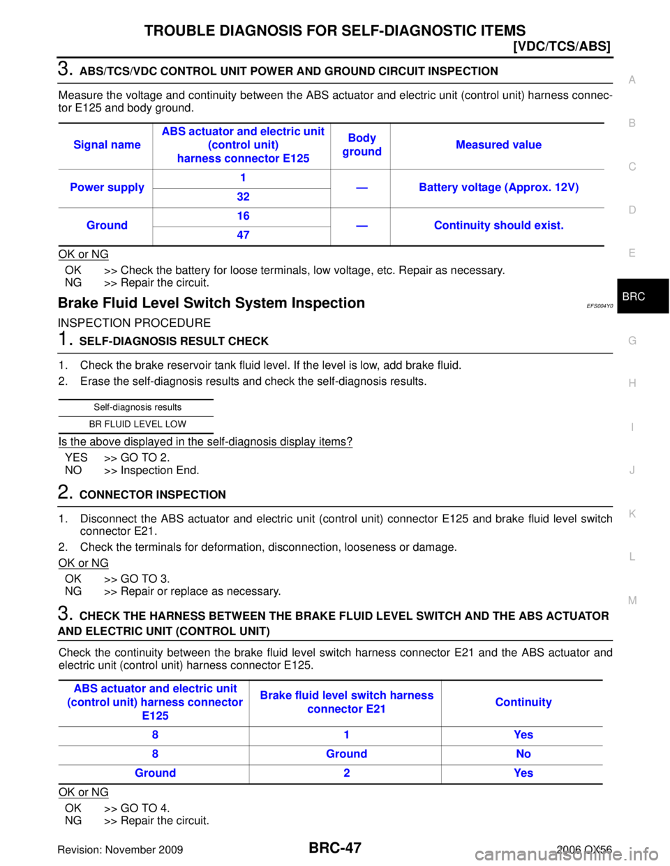
3. ABS/TCS/VDC CONTROL UNIT POWER AND GROUND CIRCUIT INSPECTION
Measure the voltage and continuity between the ABS actuator and electric unit (control unit) harness connec-
tor E125 and body ground.
OK or NG
OK >> Check the battery for loose terminals, low voltage, etc. Repair as necessary.
NG >> Repair the circuit.
Brake Fluid Level Switch System InspectionEFS004Y0
INSPECTION PROCEDURE
1. SELF-DIAGNOSIS RESULT CHECK
1. Check the brake reservoir tank fluid level. If the level is low, add brake fluid.
2. Erase the self-diagnosis results and check the self-diagnosis results.
Is the above displayed in the self-diagnosis display items?
YES >> GO TO 2.
NO >> Inspection End.
2. CONNECTOR INSPECTION
1. Disconnect the ABS actuator and electric unit (control unit) connector E125 and brake fluid level switch connector E21.
2. Check the terminals for deformation, disconnection, looseness or damage.
OK or NG
OK >> GO TO 3.
NG >> Repair or replace as necessary.
3. CHECK THE HARNESS BETWEEN THE BRAKE FLUID LEVEL SWITCH AND THE ABS ACTUATOR
AND ELECTRIC UNIT (CONTROL UNIT)
Check the continuity between the brake fluid level switch harness connector E21 and the ABS actuator and
electric unit (control unit) harness connector E125.
OK or NG
OK >> GO TO 4.
NG >> Repair the circuit. Signal name
ABS actuator and electric unit
(control unit)
harness connector E125 Body
ground Measured value
Power supply 1
— Battery voltage (Approx. 12V)
32
Ground 16
—Continuity should exist.
47
Self-diagnosis results
BR FLUID LEVEL LOW
ABS actuator and electric unit
(control unit) harness connector E125 Brake fluid level switch harness
connector E21 Continuity
81Y es
8 Ground No
Ground 2Yes
Page 1075 of 3383

BRC-48
[VDC/TCS/ABS]
TROUBLE DIAGNOSIS FOR SELF-DIAGNOSTIC ITEMS
Revision: November 20092006 QX56
4. CHECK BRAKE FLUID LEVEL SWITCH
Check continuity between brake fluid level switch terminals 1 and 2.
OK or NG
OK >> Perform self-diagnosis again. If the same results appear, replace ABS actuator and electric unit (control unit). Refer to BRC-66, "
Removal and Installation" .
NG >> Replace brake fluid level switch.
Active Booster System InspectionEFS004Y1
INSPECTION PROCEDURE
1. DISPLAY SELF DIAGNOSIS RESULTS
Check self-diagnosis results.
Is the above displayed in the self-diagnosis display items?
YES or NO
YES >> GO TO 2.
NO >> Inspection End.
2. CONNECTOR INSPECTION
1. Turn the ignition switch OFF.
2. Disconnect the active booster connector E49 and ABS actuator and electric unit (control unit) connector E125 and inspect the terminals for deformation, disconnection, looseness, or damage.
OK or NG
OK >> GO TO 3.
NG >> Repair connector. Continuity should not exist.
Self-diagnosis results
ABS ACTIVE BOOSTER SV NG
ABS ACTIVE BOOSTER RESPONSE NG ABS BRAKE RELEASE SW NG
ABS BRAKE BOOSTER DEFECT
Page 1076 of 3383

TROUBLE DIAGNOSIS FOR SELF-DIAGNOSTIC ITEMSBRC-49
[VDC/TCS/ABS]
C
DE
G H
I
J
K L
M A
B
BRC
Revision: November 2009 2006 QX56
3. ACTIVE BOOSTER CIRCUIT INSPECTION
1. Measure the continuity between the ABS actuator and electric unit (control unit) connector E125 and active booster connector E49.
2. Measure the continuity between the ABS actuator and electric unit (control unit) connector E125 and body ground.
OK or NG
OK >> GO TO 4.
NG >> Repair or replace harness or connector.
4. ACTIVE BOOSTER SENSOR INSPECTION
1. Reconnect the active booster and ABS actuator and electric unit (control unit) connectors.
2. Use "DATA MONITOR" to check if the status of "RELEASE SW NO" and "RELEASE SW NC" is normal.
OK or NG
OK >> Inspection End.
NG >> Replace active booster.
Delta Stroke Sensor System InspectionEFS004Y2
INSPECTION PROCEDURE
1. DISPLAY SELF DIAGNOSIS RESULTS
Check self-diagnosis result display item.
Is the above displayed in the self-diagnosis display items?
YES or NO
YES >> GO TO 2.
NO >> Inspection End. ABS actuator and electric unit
(control unit) connector E125 Active booster connector
E49 Continuity
17 3
Yes
27 1
28 5
30 2
31 4
ABS actuator and electric unit (control unit) connector E125 Body ground
Continuity
17
—No
27
28
30
31
Condition
Data monitor display
RELEASE SW NO RELEASE SW NC
When brake pedal is depressed ONOFF
When brake pedal is released OFFON
Self-diagnosis results
ABS DELTA S SEN NG
Page 1077 of 3383

BRC-50
[VDC/TCS/ABS]
TROUBLE DIAGNOSIS FOR SELF-DIAGNOSTIC ITEMS
Revision: November 20092006 QX56
2. CONNECTOR INSPECTION
1. Turn the ignition switch OFF.
2. Disconnect the delta stroke sensor connector E114 and ABS actuator and electric unit (control unit) con- nector E125 and inspect the terminals for deformation, disconnection, looseness, or damage.
OK or NG
OK >> GO TO 3.
NG >> Repair connector.
3. DELTA STROKE SENSOR CIRCUIT INSPECTION
1. Measure the continuity between the ABS actuator and electric unit (control unit) connector E125 and delta stroke sensor connector E114.
2. Measure the continuity between the ABS actuator and electric unit (control unit) connector E125 and body ground.
OK or NG
OK >> GO TO 4.
NG >> Repair or replace harness or connector.
4. DELTA STROKE SENSOR INSPECTION
1. Reconnect the delta stroke sensor and ABS actuator and electric unit (control unit) connectors.
2. Use "DATA MONITOR" to check if the status of "DELTA S SEN" is normal.
OK or NG
OK >> Inspection End.
NG >> Replace delta stroke sensor. ABS actuator and electric unit
(control unit) connector E125 Delta stroke sensor
connector E114 Continuity
26 1
Yes
39 3
40 5
ABS actuator and electric unit (control unit) connector E125 Body ground
Continuity
26 —No
39
40
Condition Data monitor display (Approx.)
D E LTA S S E N
When brake pedal is released 0.00 mm (+0.6/-0.4)
When brake pedal is depressed 1.05–1.80 mm
Page 1078 of 3383

TROUBLE DIAGNOSIS FOR SELF-DIAGNOSTIC ITEMSBRC-51
[VDC/TCS/ABS]
C
DE
G H
I
J
K L
M A
B
BRC
Revision: November 2009 2006 QX56
Pressure Sensor System InspectionEFS004Y3
FRONT PRESSURE INSPECTION PROCEDURE
1. DISPLAY SELF DIAGNOSIS RESULTS
Check self-diagnosis result display item.
Is the above displayed in the self-diagnosis display items?
YES or NO
YES >> GO TO 2.
NO >> Inspection End.
2. CONNECTOR INSPECTION
1. Turn the ignition switch OFF.
2. Disconnect the front pressure sensor connector E31 and ABS actuator and electric unit (control unit) con- nector E125 and inspect the terminals for deformation, disconnection, looseness, or damage.
OK or NG
OK >> GO TO 3.
NG >> Repair connector.
3. FRONT PRESSURE SENSOR CIRCUIT INSPECTION
1. Measure the continuity between the ABS actuator and electric unit (control unit) harness connector E125 and front pressure sensor harness connector E31.
2. Measure the continuity between the ABS actuator and electric unit (control unit) harness connector E125 and body ground.
OK or NG
OK >> GO TO 4.
NG >> Repair or replace harness or connector.
Self-diagnosis results
PRESS SEN CIRCUIT
ABS actuator and electric unit
(control unit) harness connector E125 Front pressure sensor har-
ness connector E31 Continuity
18 3
Yes
19 1
20 2
ABS actuator and electric unit
(control unit) harness connector E125 Body ground
Continuity
18 —No
19
20