glove box INFINITI QX56 2006 Factory Service Manual
[x] Cancel search | Manufacturer: INFINITI, Model Year: 2006, Model line: QX56, Model: INFINITI QX56 2006Pages: 3383, PDF Size: 51.76 MB
Page 549 of 3383

ATC-148
INTAKE SENSOR
Revision: November 20092006 QX56
INTAKE SENSORPFP:27723
Removal and InstallationEJS003YA
REMOVAL
1. Remove the glove box assembly. Refer to IP-15, "Glove Box" .
2. Disconnect the intake sensor electrical connector. NOTE:
The intake sensor is located on the top of the front heater and
cooling unit assembly next to the A/C evaporator cover.
3. Twist the intake sensor to remove the intake sensor from the front heater and cooling unit assembly.
INSTALLATION
Installation is in the reverse order of removal.
LJIA0133E
Page 550 of 3383

BLOWER MOTORATC-149
C
DE
F
G H
I
K L
M A
B
AT C
Revision: November 2009 2006 QX56
BLOWER MOTORPFP:27226
ComponentsEJS003YB
Front Blower Motor
Rear Blower Motor
Removal and InstallationEJS003YC
FRONT BLOWER MOTOR
Removal
1. Remove the glove box assembly. Refer to IP-14, "Lower Instrument Panel RH and Glove Box" .
2. Disconnect the front blower motor electrical connector.
3. Remove the three screws and remove the front blower motor.
Installation
Installation is in the reverse order of removal.
LJIA0136E
1. Front heater and cooling unit assembly 2. Front blower motor 3. Variable blower control
LJIA0055E
1. Rear blower motor2. Rear blower motor case 3. Rear blower motor resistor
Page 552 of 3383

IN-CABIN MICROFILTERATC-151
C
DE
F
G H
I
K L
M A
B
AT C
Revision: November 2009 2006 QX56
IN-CABIN MICROFILTERPFP:27277
Removal and InstallationEJS003YD
FUNCTION
The air inside the passenger compartment is filtered by the in-cabin
microfilters when the heater or A/C controls are set on either the
recirculation or fresh mode. The two in-cabin microfilters are located
in the front heater and cooling unit assembly. The rear heater and
cooling unit assembly only draws in air from the passenger compart-
ment to recirculate into the passenger compartment, so the rear
heater and cooling unit assembly is not equipped with in-cabin
microfilters.
REPLACEMENT TIMING
Replacement of the two in-cabin microfilters is recommended on a regular interval depending on the driving
conditions. Refer to MA-7, "
PERIODIC MAINTENANCE" . It may also be necessary to replace the two in-cabin
microfilters as part of a component replacement if the in-cabin microfilters are damaged.
REPLACEMENT PROCEDURE
1. Remove the two lower glove box hinge pins to remove the glove
box from the instrument panel and let it hang from the cord.
2. Remove the screw and remove the in-cabin microfilter cover.
3. Remove the in-cabin microfilters from the front heater and cool- ing unit assembly housing.
4. Insert the first new in-cabin microfilter into the front heater and cooling unit assembly housing and slide it over to the right.
Insert the second new in-cabin microfilter into the front heater
and cooling unit assembly housing.
NOTE:
The in-cabin microfilters are marked with air flow arrows. The
end of the microfilter with the arrow should face the rear of the
vehicle. The arrows should point downward.
LJIA0012E
WLIA0027E
LJIA0134E
LJIA0148E
Page 553 of 3383

ATC-152
IN-CABIN MICROFILTER
Revision: November 20092006 QX56
5. Install the in-cabin microfilter cover.
6. Install the lower glove box in the instrument panel and secure it
with the two hinge pins.
LJIA0134E
WLIA0027E
Page 565 of 3383

ATC-164
VARIABLE BLOWER CONTROL
Revision: November 20092006 QX56
VARIABLE BLOWER CONTROLPFP:27200
Removal and InstallationEJS003YN
Variable Blower Control - Front Heater and Cooling Unit Assembly
REMOVAL
1. Remove the glove box assembly. Refer to IP-14, "Lower Instrument Panel RH and Glove Box" .
2. Disconnect the variable blower control electrical connector.
3. Remove the two screws and remove the variable blower control.
INSTALLATION
Installation is in the reverse order of removal.
LJIA0139E
1. Front heater and cooling unit assembly 2. Intake door motor 3. Air mix door motor (driver)
4. Variable blower control 5. Air mix door motor (passenger) 6. Mode door motor
7. Defroster door motor
Page 2245 of 3383

IDX-4
ALPHABETICAL INDEX
E
ECM input/output signal ..................... EC-105
, EC-129
ECM power supply ............................. EC-145, EC-453
ECM relay ........................................................ EC-145
ECM/PW - Wiring diagram ............................... EC-454
ECTS - Wiring diagram .................................... EC-194
Electric sunroof .................................................. RF-10
Electric throttle control actuator ......... EC-534, EC-545
Electrical load signal circuit .............................. EC-596
Electrical units location ...................................... PG-65
Electronic ignition (EI) system ........................... EC-26
Engine control circuit diagram ......................... EC-103
Engine control component parts location ........... EC-96
Engine control module (ECM) .......................... EC-457
Engine control system diagram ......................... EC-23
Engine coolant .................................................. CO-10
Engine coolant temperature sensor (ECTS) ... EC-192,
EC-205
Engine fail-safe system ...................................... EC-91
Engine oil ............................................................. LU-7
Engine oil filter replacement ............................. MA-17
Engine oil precautions .......................................... GI-7
Engine oil replacement ..................................... MA-17
Engine removal ................................................. EM-74
Engine room cover ............................................ EM-12
Engine serial number .......................................... GI-49
ETC1 - Wiring diagram .................................... EC-535
ETC2 - Wiring diagram .................................... EC-530
ETC3 - Wiring diagram .................................... EC-541
EVAP canister .................................................... EC-35
EVAP canister purge volume control solenoid valve ....
EC-373
, EC-381
EVAP canister vent control valve ....... EC-388, EC-395
EVAP control system (small leak) diagnosis .. EC-365,
EC-419
, EC-427
EVAP control system pressure sensor .... EC-402, EC-
405, EC-411
EVAP control system purge flow monitoring diagnosis
EC-360
EVAP vapor lines inspection ............................. MA-20
Evaporative emission (EVAP) system ............... EC-32
Evaporator ..................................................... ATC-184
Exhaust manifold .............................................. EM-21
Exhaust system ................................................... EX-3
Exhaust system inspection .................................. EX-3
Expansion valve ............................................. ATC-186
F
F/FOG - Wiring diagram ..................................... LT-71
F/PUMP - Wiring diagram ................................ EC-605
Final drive pre-inspection ................................. FFD-15
Final drive removal and installation .. FFD-12, RFD-13
Flow charts ......................................................... GI-28
Fluid temperature sensor (A/T) ........................ AT-127
Fluids ................................................................ MA-11
Fluorescent leak detector .............................. ATC-187
Fog lamp, front .................................................... LT-69
Fog lamp, front, removal and installation ........... LT-79
Foot lamp ......................................................... LT-135
Freeze frame data ............................... EC-53, EC-118
Front brake solenoid valve ................. AT-143, AT-145
Front bumper ...................................................... EI-13
Front case (Transfer) .......................... TF-149, TF-176
Front combination lamp removal and installation LT-31
Front door ............................. BL-128, BL-131, GW-65
Front Door Trim ................................................... EI-32
Front drive shaft (Transfer) ................. TF-149, TF-176
Front fog lamp .................................................... LT-69
Front fog lamp removal and installation ............. LT-79
Front passenger air bag .................................. SRS-50
Front seat ........................................................... SE-91
Front seat belt ...................................................... SB-3
Front seat belt pre-tensioner ............... SRS-3, SRS-57
Front washer ...................................................... WW-4
Front wiper ......................................................... WW-4
FTS - Wiring diagram ....................................... AT-128
FTTS - Wiring diagram ...................... EC-311, EC-316
Fuel cut control (at no load high engine speed) EC-27
Fuel filter replacement ......................................... FL-6
Fuel gauge ............................................................ DI-5
Fuel injection system (Bank 1) .......... EC-288, EC-299
Fuel injection system (Bank 2) .......... EC-288, EC-299
Fuel injector .................................................... EC-598
Fuel injector and fuel tube ................................. EM-31
Fuel level sensor ................. EC-436, EC-438, EC-440
Fuel line inspection .............................................. FL-4
Fuel precautions ................................................... GI-5
Fuel pressure check .......................................... EC-80
Fuel pressure release ....................................... EC-80
Fuel pump ....................................................... EC-604
Fuel pump and gauge .......................................... FL-6
Fuel system .......................................................... FL-4
Fuel tank ............................................................ FL-10
Fuel tank temperature sensor ........... EC-309, EC-315
Fuel tank vacuum relief valve ........................... EC-35
FUELB1 - Wiring diagram ................. EC-290, EC-301
FUELB2 - Wiring diagram ................. EC-292, EC-303
Fuse ...................................................... PG-17, PG-77
Fuse and fusible link box .................................. PG-77
Fuse block ......................................................... PG-76
Fusible link ............................................ PG-17, PG-77
G
Garage jack and safety stand ............................. GI-41
Gauges ................................................................. DI-5
Generator .......................................................... SC-17
Generic scan tool (GST) ................................. EC-127
Glass ...................................... GW-11, GW-65, GW-68
Glove box lamp ................................................ LT-158
GPS antenna ..................................................... AV-85
Grease .............................................................. MA-11
Ground distribution ............................................ PG-31
Page 2250 of 3383

IP-1
INSTRUMENT PANEL
I BODY
CONTENTS
C
DE
F
G H
J
K L
M
SECTION
A
B
IP
Revision: November 2009 2006 QX56
PRECAUTIONS .....................................................
..... 2
Precautions for Supplemental Restraint System
(SRS) “AIR BAG” and “SEAT BELT PRE-TEN-
SIONER” ............................................................. ..... 2
PREPARATION ...................................................... ..... 3
Special Service Tools .......................................... ..... 3
Commercial Service Tools ................................... ..... 3
SQUEAK AND RATTLE TROUBLE DIAGNOSIS . ..... 4
Work Flow ................................................................ 4 CUSTOMER INTERVIEW ................................ ..... 4
DUPLICATE THE NOISE AND TEST DRIVE .. ..... 5
CHECK RELATED SERVICE BULLETINS ...... ..... 5
LOCATE THE NOISE AND IDENTIFY THE
ROOT CAUSE ................................................. ..... 5
REPAIR THE CAUSE ...................................... ..... 5
CONFIRM THE REPAIR .................................. ..... 6
Generic Squeak and Rattle Troubleshooting ...... ..... 6
INSTRUMENT PANEL ..................................... ..... 6
CENTER CONSOLE ........................................ ..... 6
DOORS ............................................................ ..... 6
TRUNK ............................................................. ..... 7
SUNROOF/HEADLINING ................................ ..... 7
OVERHEAD CONSOLE (FRONT AND REAR) ..... 7
SEATS .............................................................. ..... 7UNDERHOOD ..................................................
..... 7
Diagnostic Worksheet .......................................... ..... 8
INSTRUMENT PANEL ASSEMBLY ...................... ... 10
Removal and Installation ..................................... ... 10
REMOVAL ........................................................ ... 11
INSTALLATION ................................................ ... 11
CLUSTER LID C .............................................. ... 12
CLUSTER LID D .............................................. ... 12
INSTRUMENT LOWER COVER LH ................ ... 13
COMBINATION METER ................................... ... 13
A/T FINISHER .................................................. ... 13
Lower Instrument Panel RH and Glove Box ........ ... 14
REMOVAL AND INSTALLATION ..................... ... 14
Glove Box ............................................................ ... 15
DISASSEMBLY AND ASSEMBLY .................... ... 15
Center Console ....................................................... 16 REMOVAL AND INSTALLATION ..................... ... 16
Center Console ....................................................... 17 DISASSEMBLY AND ASSEMBLY .................... ... 17
ASSEMBLY ...................................................... ... 17
Rear Console .......................................................... 18 REMOVAL AND INSTALLATION ..................... ... 18
Rear Console .......................................................... 19 DISASSEMBLY AND ASSEMBLY .................... ... 19
Page 2260 of 3383

INSTRUMENT PANEL ASSEMBLYIP-11
C
DE
F
G H
J
K L
M A
B
IP
Revision: November 2009 2006 QX56
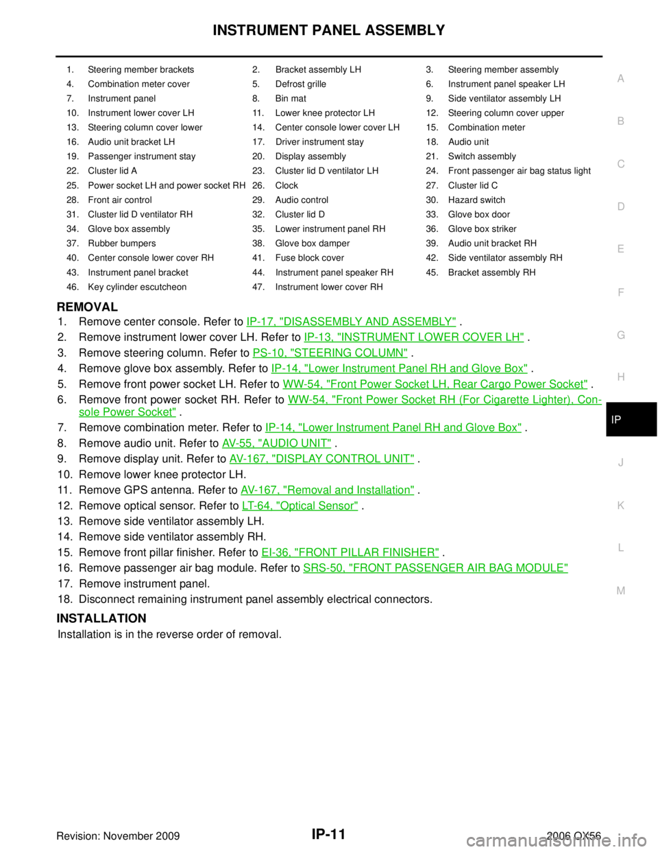
REMOVAL
1. Remove center console. Refer to IP-17, "DISASSEMBLY AND ASSEMBLY" .
2. Remove instrument lower cover LH. Refer to IP-13, "
INSTRUMENT LOWER COVER LH" .
3. Remove steering column. Refer to PS-10, "
STEERING COLUMN" .
4. Remove glove box assembly. Refer to IP-14, "
Lower Instrument Panel RH and Glove Box" .
5. Remove front power socket LH. Refer to WW-54, "
Front Power Socket LH, Rear Cargo Power Socket" .
6. Remove front power socket RH. Refer to WW-54, "
Front Power Socket RH (For Cigarette Lighter), Con-
sole Power Socket" .
7. Remove combination meter. Refer to IP-14, "
Lower Instrument Panel RH and Glove Box" .
8. Remove audio unit. Refer to AV- 5 5 , "
AUDIO UNIT" .
9. Remove display unit. Refer to AV- 1 6 7 , "
DISPLAY CONTROL UNIT" .
10. Remove lower knee protector LH.
11. Remove GPS antenna. Refer to AV- 1 6 7 , "
Removal and Installation" .
12. Remove optical sensor. Refer to LT- 6 4 , "
Optical Sensor" .
13. Remove side ventilator assembly LH.
14. Remove side ventilator assembly RH.
15. Remove front pillar finisher. Refer to EI-36, "
FRONT PILLAR FINISHER" .
16. Remove passenger air bag module. Refer to SRS-50, "
FRONT PASSENGER AIR BAG MODULE"
17. Remove instrument panel.
18. Disconnect remaining instrument panel assembly electrical connectors.
INSTALLATION
Installation is in the reverse order of removal.
1. Steering member brackets2. Bracket assembly LH3. Steering member assembly
4. Combination meter cover 5. Defrost grille6. Instrument panel speaker LH
7. Instrument panel 8. Bin mat9. Side ventilator assembly LH
10. Instrument lower cover LH 11. Lower knee protector LH12. Steering column cover upper
13. Steering column cover lower 14. Center console lower cover LH 15. Combination meter
16. Audio unit bracket LH 17. Driver instrument stay18. Audio unit
19. Passenger instrument stay 20. Display assembly21. Switch assembly
22. Cluster lid A 23. Cluster lid D ventilator LH24. Front passenger air bag status light
25. Power socket LH and power socket RH 26. Clock 27. Cluster lid C
28. Front air control 29. Audio control30. Hazard switch
31. Cluster lid D ventilator RH 32. Cluster lid D33. Glove box door
34. Glove box assembly 35. Lower instrument panel RH 36. Glove box striker
37. Rubber bumpers 38. Glove box damper39. Audio unit bracket RH
40. Center console lower cover RH 41. Fuse block cover 42. Side ventilator assembly RH
43. Instrument panel bracket 44. Instrument panel speaker RH 45. Bracket assembly RH
46. Key cylinder escutcheon 47. Instrument lower cover RH
Page 2261 of 3383

IP-12
INSTRUMENT PANEL ASSEMBLY
Revision: November 20092006 QX56
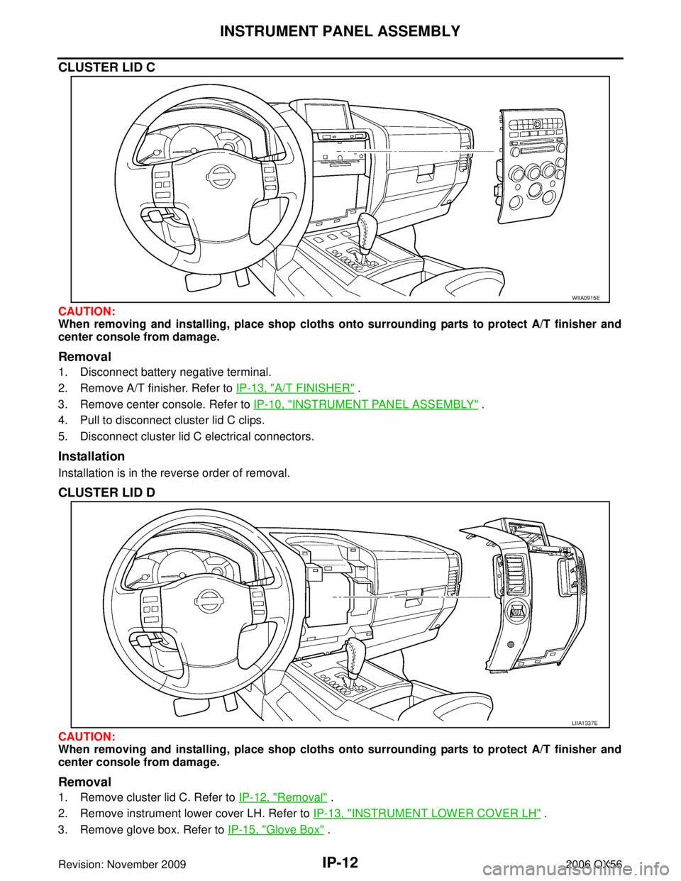
CLUSTER LID C
CAUTION:
When removing and installing, place shop cloths onto surrounding parts to protect A/T finisher and
center console from damage.
Removal
1. Disconnect battery negative terminal.
2. Remove A/T finisher. Refer to IP-13, "
A/T FINISHER" .
3. Remove center console. Refer to IP-10, "
INSTRUMENT PANEL ASSEMBLY" .
4. Pull to disconnect cluster lid C clips.
5. Disconnect cluster lid C electrical connectors.
Installation
Installation is in the reverse order of removal.
CLUSTER LID D
CAUTION:
When removing and installing, place shop cloths onto surrounding parts to protect A/T finisher and
center console from damage.
Removal
1. Remove cluster lid C. Refer to IP-12, "Removal" .
2. Remove instrument lower cover LH. Refer to IP-13, "
INSTRUMENT LOWER COVER LH" .
3. Remove glove box. Refer to IP-15, "
Glove Box" .
WIIA0915E
LIIA1337E
Page 2263 of 3383

IP-14
INSTRUMENT PANEL ASSEMBLY
Revision: November 20092006 QX56
Lower Instrument Panel RH and Glove BoxEIS007X9
REMOVAL AND INSTALLATION
Removal
1. Remove the instrument lower cover RH.
1. Clip2. Damper clip 3. Glove box damper
4. Glove box housing 5. Rubber stopper 6. Glove box pin
7. Glove box door 8. Glove box striker 9. Fuse block cover
10. Glove box assembly
LIIA1251E
LLIA0072E