check engine INFINITI QX56 2007 Factory User Guide
[x] Cancel search | Manufacturer: INFINITI, Model Year: 2007, Model line: QX56, Model: INFINITI QX56 2007Pages: 3061, PDF Size: 64.56 MB
Page 84 of 3061
AT-14
< SERVICE INFORMATION >
A/T FLUID
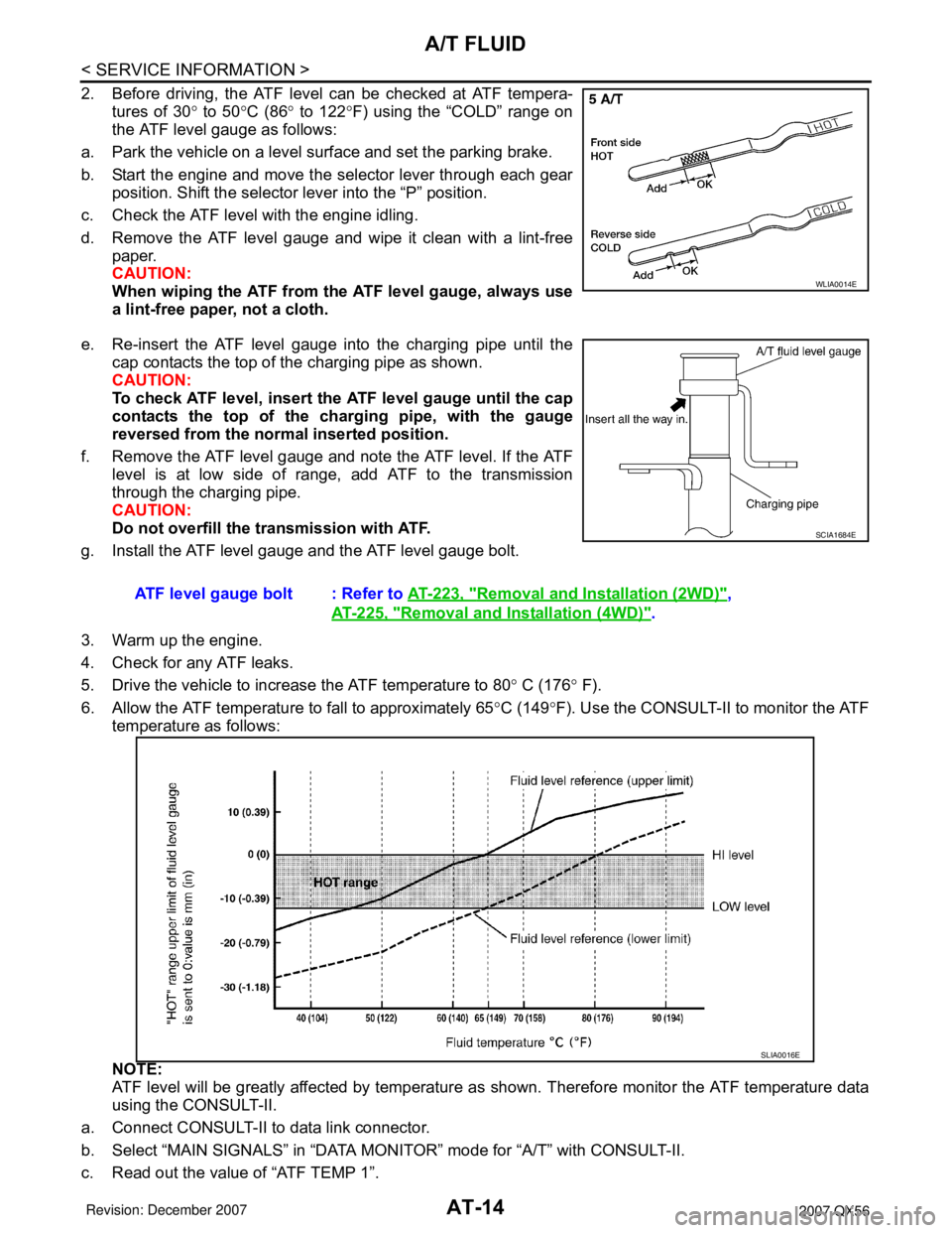
2. Before driving, the ATF level can be checked at ATF tempera-
tures of 30° to 50°C (86° to 122°F) using the “COLD” range on
the ATF level gauge as follows:
a. Park the vehicle on a level surface and set the parking brake.
b. Start the engine and move the selector lever through each gear
position. Shift the selector lever into the “P” position.
c. Check the ATF level with the engine idling.
d. Remove the ATF level gauge and wipe it clean with a lint-free
paper.
CAUTION:
When wiping the ATF from the ATF level gauge, always use
a lint-free paper, not a cloth.
e. Re-insert the ATF level gauge into the charging pipe until the
cap contacts the top of the charging pipe as shown.
CAUTION:
To check ATF level, insert the ATF level gauge until the cap
contacts the top of the charging pipe, with the gauge
reversed from the normal inserted position.
f. Remove the ATF level gauge and note the ATF level. If the ATF
level is at low side of range, add ATF to the transmission
through the charging pipe.
CAUTION:
Do not overfill the transmission with ATF.
g. Install the ATF level gauge and the ATF level gauge bolt.
3. Warm up the engine.
4. Check for any ATF leaks.
5. Drive the vehicle to increase the ATF temperature to 80° C (176° F).
6. Allow the ATF temperature to fall to approximately 65°C (149°F). Use the CONSULT-II to monitor the ATF
temperature as follows:
NOTE:
ATF level will be greatly affected by temperature as shown. Therefore monitor the ATF temperature data
using the CONSULT-II.
a. Connect CONSULT-II to data link connector.
b. Select “MAIN SIGNALS” in “DATA MONITOR” mode for “A/T” with CONSULT-II.
c. Read out the value of “ATF TEMP 1”.
WLIA0014E
ATF level gauge bolt : Refer to AT-223, "Removal and Installation (2WD)",
AT-225, "
Removal and Installation (4WD)".
SCIA1684E
SLIA0016E
Page 102 of 3061
AT-32
< SERVICE INFORMATION >
A/T CONTROL SYSTEM
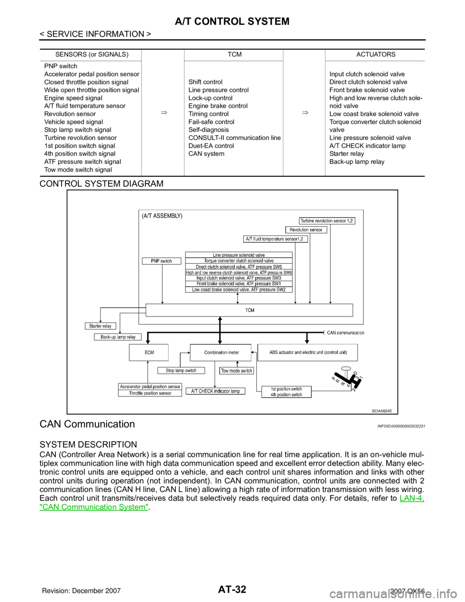
CONTROL SYSTEM DIAGRAM
CAN CommunicationINFOID:0000000003532231
SYSTEM DESCRIPTION
CAN (Controller Area Network) is a serial communication line for real time application. It is an on-vehicle mul-
tiplex communication line with high data communication speed and excellent error detection ability. Many elec-
tronic control units are equipped onto a vehicle, and each control unit shares information and links with other
control units during operation (not independent). In CAN communication, control units are connected with 2
communication lines (CAN H line, CAN L line) allowing a high rate of information transmission with less wiring.
Each control unit transmits/receives data but selectively reads required data only. For details, refer to LAN-4,
"CAN Communication System".
SENSORS (or SIGNALS)
⇒TCM
⇒ACTUATORS
PNP switch
Accelerator pedal position sensor
Closed throttle position signal
Wide open throttle position signal
Engine speed signal
A/T fluid temperature sensor
Revolution sensor
Vehicle speed signal
Stop lamp switch signal
Turbine revolution sensor
1st position switch signal
4th position switch signal
ATF pressure switch signal
Tow mode switch signalShift control
Line pressure control
Lock-up control
Engine brake control
Timing control
Fail-safe control
Self-diagnosis
CONSULT-II communication line
Duet-EA control
CAN systemInput clutch solenoid valve
Direct clutch solenoid valve
Front brake solenoid valve
High and low reverse clutch sole-
noid valve
Low coast brake solenoid valve
Torque converter clutch solenoid
valve
Line pressure solenoid valve
A/T CHECK indicator lamp
Starter relay
Back-up lamp relay
SCIA5624E
Page 109 of 3061

ON BOARD DIAGNOSTIC (OBD) SYSTEM
AT-39
< SERVICE INFORMATION >
D
E
F
G
H
I
J
K
L
MA
B
AT
N
O
P
ON BOARD DIAGNOSTIC (OBD) SYSTEM
IntroductionINFOID:0000000003532238
The A/T system has two self-diagnostic systems.
The first is the emission-related on board diagnostic system (OBD-II) performed by the TCM in combination
with the ECM. The malfunction is indicated by the MIL (malfunction indicator lamp) and is stored as a DTC in
the ECM memory but not the TCM memory.
The second is the TCM original self-diagnosis indicated by the A/T CHECK indicator lamp. The malfunction is
stored in the TCM memory. The detected items are overlapped with OBD-II self-diagnostic items. For detail,
refer to AT-83, "
CONSULT-II Function (A/T)".
OBD-II Function for A/T SystemINFOID:0000000003532239
The ECM provides emission-related on board diagnostic (OBD-II) functions for the A/T system. One function
is to receive a signal from the TCM used with OBD-related parts of the A/T system. The signal is sent to the
ECM when a malfunction occurs in the corresponding OBD-related part. The other function is to indicate a
diagnostic result by means of the MIL (malfunction indicator lamp) on the instrument panel. Sensors, switches
and solenoid valves are used as sensing elements.
The MIL automatically illuminates in One or Two Trip Detection Logic when a malfunction is sensed in relation
to A/T system parts.
One or Two Trip Detection Logic of OBD-IIINFOID:0000000003532240
ONE TRIP DETECTION LOGIC
If a malfunction is sensed during the first test drive, the MIL will illuminate and the malfunction will be stored in
the ECM memory as a DTC. The TCM is not provided with such a memory function.
TWO TRIP DETECTION LOGIC
When a malfunction is sensed during the first test drive, it is stored in the ECM memory as a 1st trip DTC
(diagnostic trouble code) or 1st trip freeze frame data. At this point, the MIL will not illuminate. — 1st Trip
If the same malfunction as that experienced during the first test drive is sensed during the second test drive,
the MIL will illuminate. — 2nd Trip
The “Trip” in the “One or Two Trip Detection Logic” means a driving mode in which self-diagnosis is performed
during vehicle operation.
OBD-II Diagnostic Trouble Code (DTC)INFOID:0000000003532241
HOW TO READ DTC AND 1ST TRIP DTC
DTC and 1st trip DTC can be read by the following methods.
( with CONSULT-II or GST) CONSULT-II or GST (Generic Scan Tool) Examples: P0705, P0720 etc.
These DTC are prescribed by SAE J2012.
(CONSULT-II also displays the malfunctioning component or system.)
•1st trip DTC No. is the same as DTC No.
•Output of the diagnostic trouble code indicates that the indicated circuit has a malfunction. How-
ever, in case of the Mode II and GST, they do not indicate whether the malfunction is still occurring or
occurred in the past and returned to normal.
CONSULT-II can identify them as shown below, therefore, CONSULT-II (if available) is recommended.
A sample of CONSULT-II display for DTC and 1st trip DTC is shown
on the next page. DTC or 1st trip DTC of a malfunction is displayed
in SELF-DIAGNOSTIC RESULTS mode for “ENGINE” with CON-
SULT-II. Time data indicates how many times the vehicle was driven
after the last detection of a DTC.
BCIA0030E
Page 112 of 3061

AT-42
< SERVICE INFORMATION >
ON BOARD DIAGNOSTIC (OBD) SYSTEM
The MIL is located on the instrument panel.
1. The MIL will light up when the ignition switch is turned “ON” with-
out the engine running. This is a bulb check.
• If the MIL does not light up, refer to DI-26
.
2. When the engine is started, the MIL should go off.
If the MIL remains on, the on board diagnostic system has
detected an engine system malfunction.
SEF217U
Page 115 of 3061

TROUBLE DIAGNOSIS
AT-45
< SERVICE INFORMATION >
D
E
F
G
H
I
J
K
L
MA
B
AT
N
O
P
It is much more difficult to diagnose a error that occurs intermittently
rather than continuously. Most intermittent errors are caused by poor
electric connections or improper wiring. In this case, careful check-
ing of suspected circuits may help prevent the replacement of good
parts.
A visual check only may not find the cause of the errors. A road test
with CONSULT-II (or GST) or a circuit tester connected should be
performed. Follow the "WORK FLOW".
Before undertaking actual checks, take a few minutes to talk with a
customer who approaches with a driveability complaint. The cus-
tomer can supply good information about such errors, especially
intermittent ones. Find out what symptoms are present and under
what conditions they occur. A “Diagnostic Worksheet” as shown on
the example (Refer to "Diagnostic Worksheet Chart") should be
used.
Start your diagnosis by looking for “conventional” errors first. This will
help troubleshoot driveability errors on an electronically controlled
engine vehicle.
Also check related Service bulletins.
WORK FLOW
A good understanding of the malfunction conditions can make troubleshooting faster and more accurate.
In general, each customer feels differently about a malfunction. It is important to fully understand the symp-
toms or conditions for a customer complaint.
Make good use of the two sheets provided, “Information From Customer” (Refer to "Information From Cus-
tomer") and “Diagnostic Worksheet” (Refer to "Diagnostic Worksheet Chart"), to perform the best trouble-
shooting possible.
Work Flow Chart
SAT632I
SEF234G
Page 118 of 3061
AT-48
< SERVICE INFORMATION >
TROUBLE DIAGNOSIS
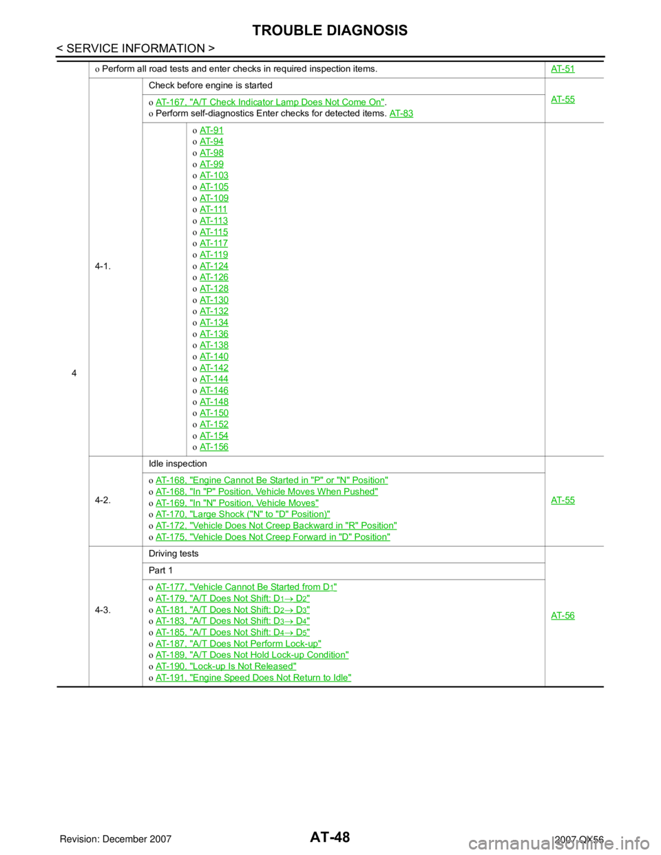
4o Perform all road tests and enter checks in required inspection items.AT- 5 1
4-1.Check before engine is started
AT- 5 5
o AT- 1 6 7 , "A/T Check Indicator Lamp Does Not Come On".
o Perform self-diagnostics Enter checks for detected items. AT- 8 3
o AT- 9 1
o AT- 9 4
o AT- 9 8
o AT- 9 9
o AT- 1 0 3
o AT- 1 0 5
o AT- 1 0 9
o AT- 111
o AT- 11 3
o AT- 11 5
o AT- 11 7
o AT- 11 9
o AT- 1 2 4
o AT- 1 2 6
o AT- 1 2 8
o AT- 1 3 0
o AT- 1 3 2
o AT- 1 3 4
o AT- 1 3 6
o AT- 1 3 8
o AT- 1 4 0
o AT- 1 4 2
o AT- 1 4 4
o AT- 1 4 6
o AT- 1 4 8
o AT- 1 5 0
o AT- 1 5 2
o AT- 1 5 4
o AT- 1 5 6
4-2.Idle inspection
AT- 5 5
o AT- 1 6 8 , "Engine Cannot Be Started in "P" or "N" Position"
o AT- 1 6 8 , "In "P" Position, Vehicle Moves When Pushed"
o AT- 1 6 9 , "In "N" Position, Vehicle Moves"
o AT- 1 7 0 , "Large Shock ("N" to "D" Position)"
o AT- 1 7 2 , "Vehicle Does Not Creep Backward in "R" Position"
o AT- 1 7 5 , "Vehicle Does Not Creep Forward in "D" Position"
4-3.Driving tests
AT- 5 6
Part 1
o AT- 1 7 7 , "
Vehicle Cannot Be Started from D1"
o AT- 1 7 9 , "A/T Does Not Shift: D1→ D2"
o AT- 1 8 1 , "A/T Does Not Shift: D2→ D3"
o AT- 1 8 3 , "A/T Does Not Shift: D3→ D4"
o AT- 1 8 5 , "A/T Does Not Shift: D4→ D5"
o AT- 1 8 7 , "A/T Does Not Perform Lock-up"
o AT- 1 8 9 , "A/T Does Not Hold Lock-up Condition"
o AT- 1 9 0 , "Lock-up Is Not Released"
o AT- 1 9 1 , "Engine Speed Does Not Return to Idle"
Page 119 of 3061
TROUBLE DIAGNOSIS
AT-49
< SERVICE INFORMATION >
D
E
F
G
H
I
J
K
L
MA
B
AT
N
O
P
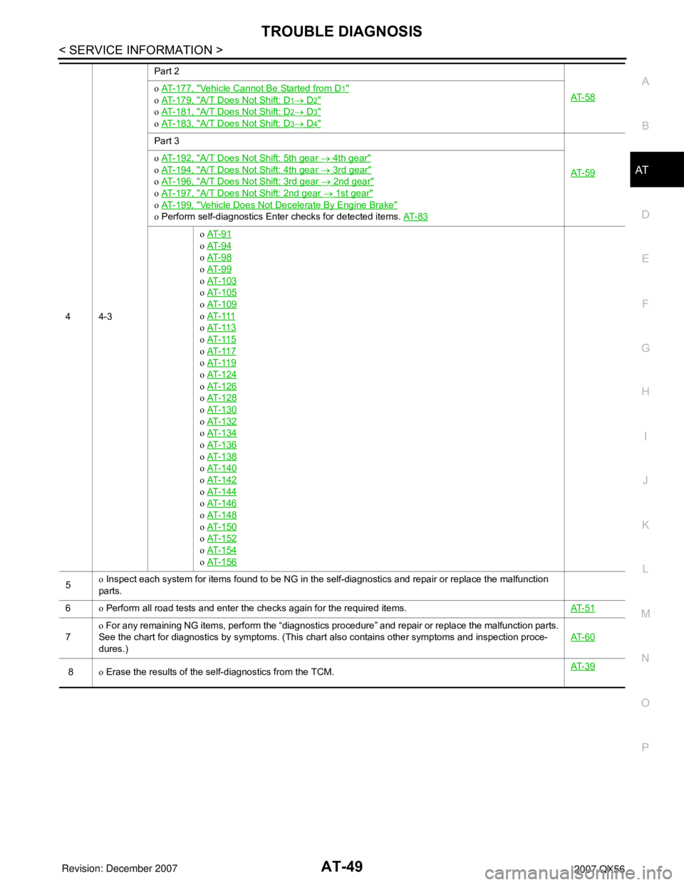
44-3Part 2
AT- 5 8
o AT- 1 7 7 , "Vehicle Cannot Be Started from D1"
o AT- 1 7 9 , "A/T Does Not Shift: D1→ D2"
o AT- 1 8 1 , "A/T Does Not Shift: D2→ D3"
o AT- 1 8 3 , "A/T Does Not Shift: D3→ D4"
Part 3
AT- 5 9
o AT- 1 9 2 , "A/T Does Not Shift: 5th gear → 4th gear"
o AT- 1 9 4 , "A/T Does Not Shift: 4th gear → 3rd gear"
o AT- 1 9 6 , "A/T Does Not Shift: 3rd gear → 2nd gear"
o AT- 1 9 7 , "A/T Does Not Shift: 2nd gear → 1st gear"
o AT- 1 9 9 , "Vehicle Does Not Decelerate By Engine Brake"
o Perform self-diagnostics Enter checks for detected items. AT- 8 3
o AT- 9 1
o AT- 9 4
o AT- 9 8
o AT- 9 9
o AT- 1 0 3
o AT- 1 0 5
o AT- 1 0 9
o AT- 111
o AT- 11 3
o AT- 11 5
o AT- 11 7
o AT- 11 9
o AT- 1 2 4
o AT- 1 2 6
o AT- 1 2 8
o AT- 1 3 0
o AT- 1 3 2
o AT- 1 3 4
o AT- 1 3 6
o AT- 1 3 8
o AT- 1 4 0
o AT- 1 4 2
o AT- 1 4 4
o AT- 1 4 6
o AT- 1 4 8
o AT- 1 5 0
o AT- 1 5 2
o AT- 1 5 4
o AT- 1 5 6
5o Inspect each system for items found to be NG in the self-diagnostics and repair or replace the malfunction
parts.
6o Perform all road tests and enter the checks again for the required items.AT- 5 1
7o For any remaining NG items, perform the “diagnostics procedure” and repair or replace the malfunction parts.
See the chart for diagnostics by symptoms. (This chart also contains other symptoms and inspection proce-
dures.)AT- 6 0
8o Erase the results of the self-diagnostics from the TCM.AT- 3 9
Page 122 of 3061
AT-52
< SERVICE INFORMATION >
TROUBLE DIAGNOSIS
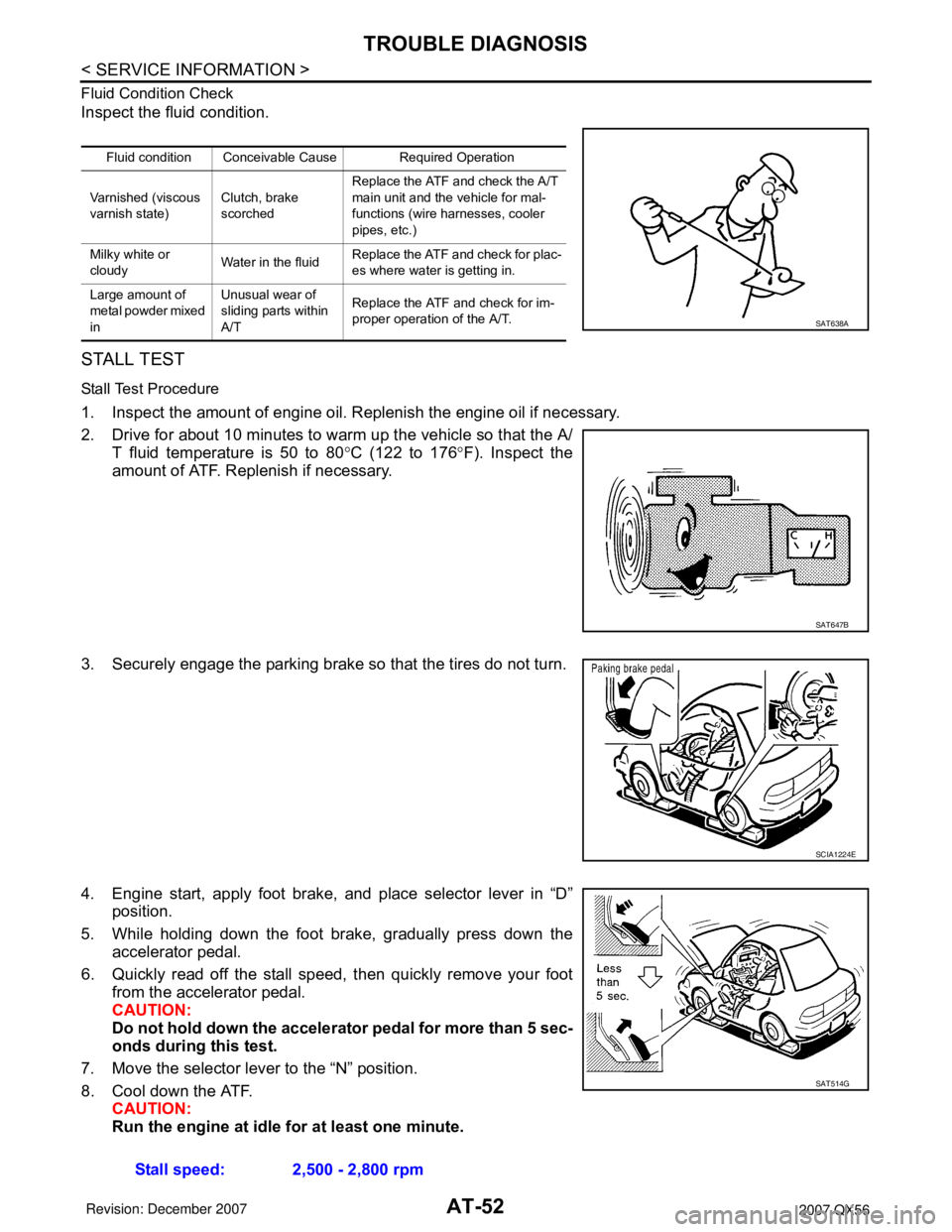
Fluid Condition Check
Inspect the fluid condition.
STALL TEST
Stall Test Procedure
1. Inspect the amount of engine oil. Replenish the engine oil if necessary.
2. Drive for about 10 minutes to warm up the vehicle so that the A/
T fluid temperature is 50 to 80°C (122 to 176°F). Inspect the
amount of ATF. Replenish if necessary.
3. Securely engage the parking brake so that the tires do not turn.
4. Engine start, apply foot brake, and place selector lever in “D”
position.
5. While holding down the foot brake, gradually press down the
accelerator pedal.
6. Quickly read off the stall speed, then quickly remove your foot
from the accelerator pedal.
CAUTION:
Do not hold down the accelerator pedal for more than 5 sec-
onds during this test.
7. Move the selector lever to the “N” position.
8. Cool down the ATF.
CAUTION:
Run the engine at idle for at least one minute.
Fluid condition Conceivable Cause Required Operation
Varnished (viscous
varnish state)Clutch, brake
scorchedReplace the ATF and check the A/T
main unit and the vehicle for mal-
functions (wire harnesses, cooler
pipes, etc.)
Milky white or
cloudyWater in the fluidReplace the ATF and check for plac-
es where water is getting in.
Large amount of
metal powder mixed
inUnusual wear of
sliding parts within
A/TReplace the ATF and check for im-
proper operation of the A/T.
SAT638A
SAT647B
SCIA1224E
Stall speed: 2,500 - 2,800 rpm
SAT514G
Page 125 of 3061
TROUBLE DIAGNOSIS
AT-55
< SERVICE INFORMATION >
D
E
F
G
H
I
J
K
L
MA
B
AT
N
O
P
ROAD TEST
Description
• The road test inspects overall performance of the A/T and analyzes possible malfunction causes.
• The road test is carried out in the following three stages.
1. Check before engine is started. Refer to AT- 5 5
.
2. Check at idle. Refer to AT- 5 5
3. Cruise test
• Inspect all the items from Part 1 to Part 3. Refer to AT- 5 6
, AT- 5 8, AT- 5 9.
• Before beginning the road test, check the test procedure and inspection items.
• Test all inspection items until the symptom is uncovered. Diagnose NG items when all road tests are com-
plete.
Check Before Engine Is StartedINFOID:0000000003532249
1.CHECK AT CHECK INDICATOR LAMP
1. Park vehicle on level surface.
2. Move selector lever to “P” position.
3. Turn ignition switch to “OFF” position and wait at least 10 seconds.
4. Turn ignition switch to “ON” position. (Do not start engine.)
Does AT CHECK indicator lamp light up for about 2 seconds?
YES >> 1. Turn ignition switch to “OFF” position.
2. Carry out the self-diagnostics and record all NG items on the diagnostics worksheet. Refer to
AT-83, "
CONSULT-II Function (A/T)".
3. Go to AT-55, "
Check at Idle".
NO >> Stop the road test and go to AT-167, "
A/T Check Indicator Lamp Does Not Come On".
Check at IdleINFOID:0000000003532250
1.CHECK STARTING THE ENGINE
1. Park vehicle on level surface.
2. Move selector lever to “P” or “N” position.
3. Turn ignition switch to “OFF” position.
4. Turn ignition switch to “START” position.
Does the engine start?
YES >> GO TO 2.
NO >> Stop the road test and go to AT-168, "
Engine Cannot Be Started in "P" or "N" Position".
2.CHECK STARTING THE ENGINE
1. Turn ignition switch to “ON” position.
2. Move selector lever in “D”,“4”, “3”, “2”, “1” or “R” position.
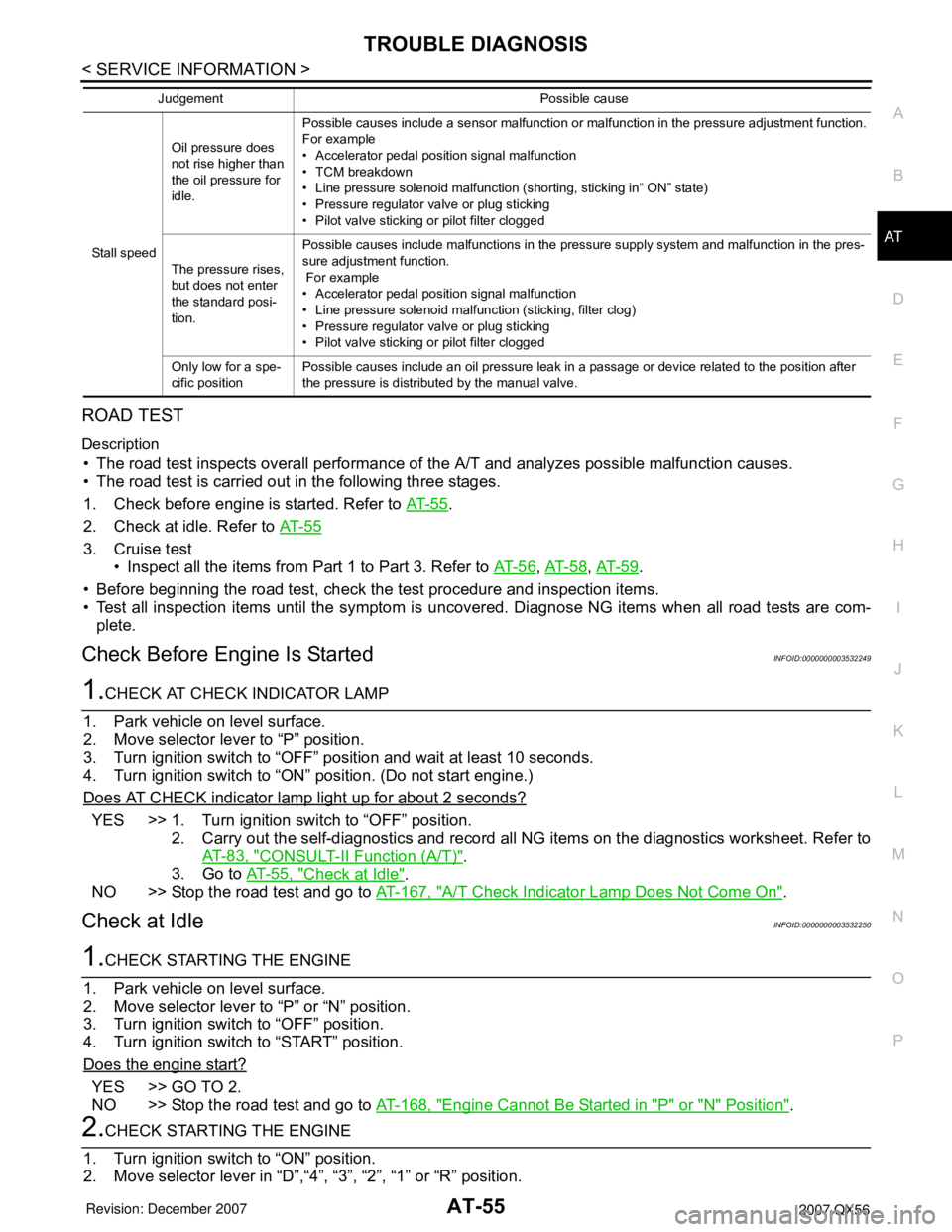
Stall speedOil pressure does
not rise higher than
the oil pressure for
idle.Possible causes include a sensor malfunction or malfunction in the pressure adjustment function.
For example
• Accelerator pedal position signal malfunction
• TCM breakdown
• Line pressure solenoid malfunction (shorting, sticking in“ ON” state)
• Pressure regulator valve or plug sticking
• Pilot valve sticking or pilot filter clogged
The pressure rises,
but does not enter
the standard posi-
tion.Possible causes include malfunctions in the pressure supply system and malfunction in the pres-
sure adjustment function.
For example
• Accelerator pedal position signal malfunction
• Line pressure solenoid malfunction (sticking, filter clog)
• Pressure regulator valve or plug sticking
• Pilot valve sticking or pilot filter clogged
Only low for a spe-
cific positionPossible causes include an oil pressure leak in a passage or device related to the position after
the pressure is distributed by the manual valve. Judgement Possible cause
Page 126 of 3061
AT-56
< SERVICE INFORMATION >
TROUBLE DIAGNOSIS
3. Turn ignition switch to “START” position.
Does the engine start in either position?
YES >> Stop the road test and go to AT-168, "Engine Cannot Be Started in "P" or "N" Position".
NO >> GO TO 3.
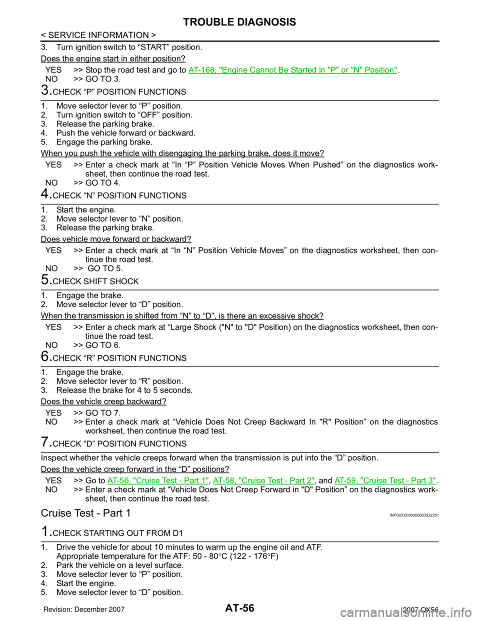
3.CHECK “P” POSITION FUNCTIONS
1. Move selector lever to “P” position.
2. Turn ignition switch to “OFF” position.
3. Release the parking brake.
4. Push the vehicle forward or backward.
5. Engage the parking brake.
When you push the vehicle with disengaging the parking brake, does it move?
YES >> Enter a check mark at “In “P” Position Vehicle Moves When Pushed” on the diagnostics work-
sheet, then continue the road test.
NO >> GO TO 4.
4.CHECK “N” POSITION FUNCTIONS
1. Start the engine.
2. Move selector lever to “N” position.
3. Release the parking brake.
Does vehicle move forward or backward?
YES >> Enter a check mark at “In “N” Position Vehicle Moves” on the diagnostics worksheet, then con-
tinue the road test.
NO >> GO TO 5.
5.CHECK SHIFT SHOCK
1. Engage the brake.
2. Move selector lever to “D” position.
When the transmission is shifted from
“N” to “D”, is there an excessive shock?
YES >> Enter a check mark at “Large Shock ("N" to "D" Position) on the diagnostics worksheet, then con-
tinue the road test.
NO >> GO TO 6.
6.CHECK “R” POSITION FUNCTIONS
1. Engage the brake.
2. Move selector lever to “R” position.
3. Release the brake for 4 to 5 seconds.
Does the vehicle creep backward?
YES >> GO TO 7.
NO >> Enter a check mark at “Vehicle Does Not Creep Backward In "R" Position” on the diagnostics
worksheet, then continue the road test.
7.CHECK “D” POSITION FUNCTIONS
Inspect whether the vehicle creeps forward when the transmission is put into the “D” position.
Does the vehicle creep forward in the
“D” positions?
YES >> Go to AT-56, "Cruise Test - Part 1", AT-58, "Cruise Test - Part 2", and AT-59, "Cruise Test - Part 3".
NO >> Enter a check mark at “Vehicle Does Not Creep Forward in "D" Position” on the diagnostics work-
sheet, then continue the road test.
Cruise Test - Part 1INFOID:0000000003532251
1.CHECK STARTING OUT FROM D1
1. Drive the vehicle for about 10 minutes to warm up the engine oil and ATF.
Appropriate temperature for the ATF: 50 - 80°C (122 - 176°F)
2. Park the vehicle on a level surface.
3. Move selector lever to “P” position.
4. Start the engine.
5. Move selector lever to “D” position.