automatic transmission fluid INFINITI QX56 2007 Factory Owner's Manual
[x] Cancel search | Manufacturer: INFINITI, Model Year: 2007, Model line: QX56, Model: INFINITI QX56 2007Pages: 3061, PDF Size: 64.56 MB
Page 268 of 3061

AT-198
< SERVICE INFORMATION >
TROUBLE DIAGNOSIS FOR SYMPTOMS
1. Turn ignition switch “ON”.
2. Select "ECU INPUT SIGNALS" in "DATA MONITOR" mode for
"A/T" with CONSULT-II.
3. Read out "1 POSITION SW" switch moving selector lever to
each position.
Without CONSULT-II
1. Turn ignition switch “ON”. (Do not start engine)
2. Check voltage between A/T device harness connector terminal
and ground.
OK or NG
OK >> GO TO 3.
NG >> Repair or replace damaged parts.
3.CHECK A/T FLUID LEVEL
Check the A/T fluid level. Refer to AT-13, "
Checking Automatic
Transmission Fluid (ATF)".
OK or NG
OK >> GO TO 4.
NG >> Refill ATF.
4.CHECK CONTROL CABLE
Check the control cable.
• Refer to AT-208, "
Checking of A/T Position".
OK or NG
OK >> GO TO 5.
NG >> Adjust control cable. Refer to AT-208, "
Adjustment of A/
T Position".
5.CHECK A/T FLUID CONDITION
Monitor item Condition Display value
1 POSITION SWWhen setting the selector
lever to "1" position.ON
When setting selector le-
ver to other positions.OFF
LCIA0339E
Item Connector No. Terminal No. ConditionData
(Approx.)
1st position
switchM203 7 - GroundWhen setting
the selector le-
ver to "1" posi-
tion.0V
When setting
selector lever
to other posi-
tions.Battery volt-
age
LCIA0341E
SAT638A
LCIA0345E
Page 270 of 3061

AT-200
< SERVICE INFORMATION >
TROUBLE DIAGNOSIS FOR SYMPTOMS
1. Turn ignition switch “ON”.
2. Select "ECU INPUT SIGNALS" in "DATA MONITOR" mode for
"A/T" with CONSULT-II.
3. Read out "1 POSITION SW" moving switch selector lever to
each position.
Without CONSULT-II
1. Turn ignition switch “ON”. (Do not start engine)
2. Check voltage between A/T device harness connector terminal
and ground.
OK or NG
OK >> GO TO 3.
NG >> Repair or replace damaged parts.
3.CHECK A/T FLUID LEVEL
Check the A/T fluid level. Refer to AT-13, "
Checking Automatic
Transmission Fluid (ATF)".
OK or NG
OK >> GO TO 4.
NG >> Refill ATF.
4.CHECK CONTROL CABLE
Check the control cable.
• Refer to AT-208, "
Checking of A/T Position".
OK or NG
OK >> GO TO 5.
NG >> Adjust control cable. Refer to AT-208, "
Adjustment of A/
T Position".
5.CHECK A/T FLUID CONDITION
Monitor item Condition Display value
1 POSITION SWWhen setting the selector
lever to "1" position.ON
When setting selector le-
ver to other positions.OFF
LCIA0339E
Item Connector No. Terminal No. ConditionData
(Approx.)
1st position
switchM203 7 - GroundWhen setting
the selector le-
ver to "1" posi-
tion.0V
When setting
selector lever
to other posi-
tions.Battery volt-
age
LCIA0341E
SAT638A
LCIA0345E
Page 279 of 3061

ON-VEHICLE SERVICE
AT-209
< SERVICE INFORMATION >
D
E
F
G
H
I
J
K
L
MA
B
AT
N
O
P
ON-VEHICLE SERVICE
Oil PanINFOID:0000000003532477
REMOVAL AND INSTALLATION
Removal
1. Drain A/T fluid. Refer to AT-13, "Changing Automatic Transmission Fluid (ATF)".
2. Remove oil pan clips (1).
3. Remove oil pan (2).
4. Remove oil pan gasket.
• : Front
• : Oil pan bolts
• Drain plug (3)
5. Check foreign materials in oil pan to help determine cause of malfunction. If the A/T fluid is very dark, has
some burned smell, or contains foreign particles, friction material (clutches, band) may need replacement.
A tacky film that will not wipe clean indicates varnish build up. Varnish can cause valves, servo, and
clutches to stick and can inhibit pump pressure.
CAUTION:
If friction material is detected, flush the transmission cooler after repair. Refer to AT-15, "
A/T Fluid
Cooler Cleaning".
6. Remove magnets from oil pan.
Installation
1. Install the oil pan magnets as shown.
AWDIA0023ZZ
SCIA5200E
SCIA5200E
Page 280 of 3061

AT-210
< SERVICE INFORMATION >
ON-VEHICLE SERVICE
2. Install the oil pan (2) and new oil pan gasket.
• Oil pan clips (1)
• Drain plug (3)
• : Front
• : Oil pan bolts
CAUTION:
• Do not reuse the oil pan gasket.
• Completely remove all moisture, oil and old gasket from
the oil pan gasket mating surfaces and holes.
• Always replace the oil pan bolts as they are self-sealing.
• Be sure the oil pan drain plug hole is located to the rear of
the transmission assembly.
• Partially install the oil pan bolts in a criss-cross pattern to prevent dislocation of the gasket.
• Be careful not to pinch harnesses.
3. Tighten new oil pan bolts in numerical order as shown.
4. Install drain plug in oil pan with new gasket.
CAUTION:
Do not reuse the drain plug gasket.
5. Refill the transmission assembly with fluid. Refer to AT-13, "
Changing Automatic Transmission Fluid
(ATF)".
Control Valve with TCM and A/T Fluid Temperature Sensor 2INFOID:0000000003532478
COMPONENTS
AWDIA0023ZZ
Oil pan bolts : 7.9 N·m (0.81 kg-m, 70 in-lb)
SCIA4113E
Drain plug : 34 N·m (3.5 kg-m, 25 ft-lb)
Page 288 of 3061

AT-218
< SERVICE INFORMATION >
ON-VEHICLE SERVICE
17. Install snap ring to A/T assembly harness connector.
18. Connect A/T assembly harness connector.
19. Connect the negative battery terminal
20. Refill the A/T with fluid and check fluid level and for fluid leak-
age. Refer to AT-13, "
Changing Automatic Transmission Fluid
(ATF)".
CAUTION:
After completing installation, check A/T fluid leakage and fluid
level. Refer to AT-13, "
Changing Automatic Transmission Fluid
(ATF)", AT-13, "Checking Automatic Transmission Fluid (ATF)".
A/T FLUID TEMPERATURE SENSOR 2 REMOVAL AND INSTALLATION
Removal
1. Disconnect negative battery terminal
2. Remove oil pan and oil pan gasket. Refer to AT-209, "
Oil Pan".
3. Disconnect A/T fluid temperature sensor 2 connector (A).
CAUTION:
Be careful not to damage connector.
4. Straighten terminal clip to free A/T fluid temperature sensor 2
harness.
• : Terminal clip
5. Remove A/T fluid temperature sensor 2 with bracket from con-
trol valve with TCM.
6. Remove bracket from A/T fluid temperature sensor 2.
Installation
SCIA5039E
SCIA8125E
SCIA5253E
SCIA5264E
Page 289 of 3061

ON-VEHICLE SERVICE
AT-219
< SERVICE INFORMATION >
D
E
F
G
H
I
J
K
L
MA
B
AT
N
O
P
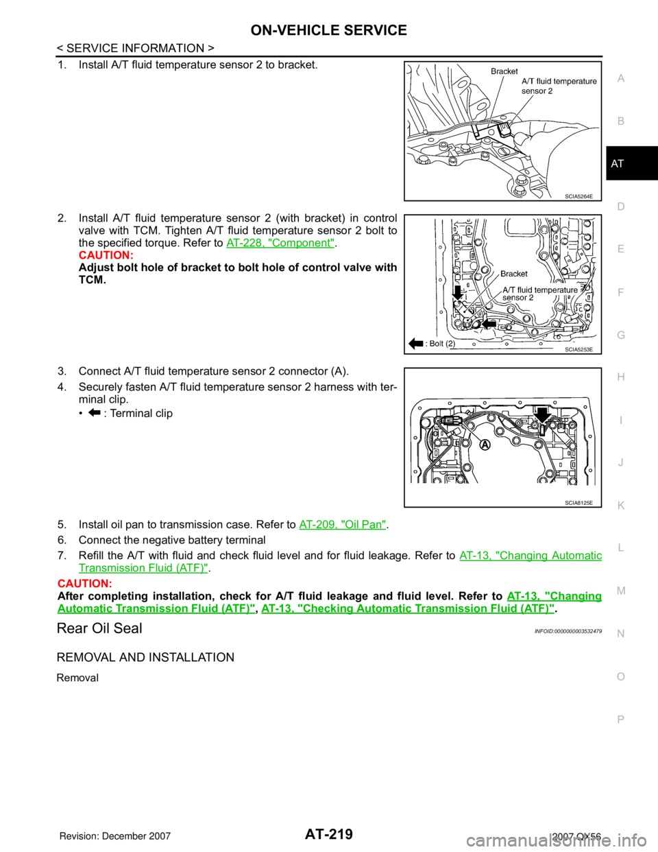
1. Install A/T fluid temperature sensor 2 to bracket.
2. Install A/T fluid temperature sensor 2 (with bracket) in control
valve with TCM. Tighten A/T fluid temperature sensor 2 bolt to
the specified torque. Refer to AT-228, "
Component".
CAUTION:
Adjust bolt hole of bracket to bolt hole of control valve with
TCM.
3. Connect A/T fluid temperature sensor 2 connector (A).
4. Securely fasten A/T fluid temperature sensor 2 harness with ter-
minal clip.
• : Terminal clip
5. Install oil pan to transmission case. Refer to AT-209, "
Oil Pan".
6. Connect the negative battery terminal
7. Refill the A/T with fluid and check fluid level and for fluid leakage. Refer to AT-13, "
Changing Automatic
Transmission Fluid (ATF)".
CAUTION:
After completing installation, check for A/T fluid leakage and fluid level. Refer to AT-13, "
Changing
Automatic Transmission Fluid (ATF)", AT-13, "Checking Automatic Transmission Fluid (ATF)".
Rear Oil SealINFOID:0000000003532479
REMOVAL AND INSTALLATION
Removal
SCIA5264E
SCIA5253E
SCIA8125E
Page 290 of 3061

AT-220
< SERVICE INFORMATION >
ON-VEHICLE SERVICE
1. Remove rear propeller shaft. Refer to PR-8, "Removal and
Installation".
2. Remove transfer from transmission (4WD models). Refer to TF-
128, "Removal and Installation".
3. Remove rear oil seal using suitable tool.
CAUTION:
Be careful not to scratch rear extension assembly (2WD
models) or adapter case assembly (4WD models).
Installation
1. Install new rear oil seal until it is flush with component face into
the extension case (2WD models) using Tool, or adapter case
(4WD models) using suitable tool.
CAUTION:
• Apply ATF to rear oil seal.
• Do not reuse rear oil seal.
2. Install transfer to transmission (4WD models). Refer to TF-128,
"Removal and Installation".
3. Install rear propeller shaft. Refer to PR-8, "
Removal and Installa-
tion".
CAUTION:
After completing installation, check for A/T fluid leakage and
fluid level. Refer to AT-13, "
Changing Automatic Transmission
Fluid (ATF)" and AT-13, "Checking Automatic Transmission
Fluid (ATF)".
SCIA5254E
Tool number : ST33400001 (J-26082)
SCIA5583E
Page 295 of 3061

TRANSMISSION ASSEMBLY
AT-225
< SERVICE INFORMATION >
D
E
F
G
H
I
J
K
L
MA
B
AT
N
O
P
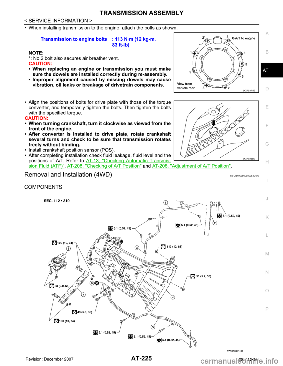
• When installing transmission to the engine, attach the bolts as shown.
NOTE:
*: No.2 bolt also secures air breather vent.
CAUTION:
• When replacing an engine or transmission you must make
sure the dowels are installed correctly during re-assembly.
• Improper alignment caused by missing dowels may cause
vibration, oil leaks or breakage of drivetrain components.
• Align the positions of bolts for drive plate with those of the torque
converter, and temporarily tighten the bolts. Then tighten the bolts
with the specified torque.
CAUTION:
• When turning crankshaft, turn it clockwise as viewed from the
front of the engine.
• After converter is installed to drive plate, rotate crankshaft
several turns and check to be sure that transmission rotates
freely without binding.
• Install crankshaft position sensor (POS).
• After completing installation check fluid leakage, fluid level and the
positions of A/T. Refer to AT-13, "
Checking Automatic Transmis-
sion Fluid (ATF)", AT-208, "Checking of A/T Position" and AT-208, "Adjustment of A/T Position".
Removal and Installation (4WD)INFOID:0000000003532482
COMPONENTS
Transmission to engine bolts : 113 N·m (12 kg-m,
83 ft-lb)
LCIA0371E
LCIA0335E
AWDIA0441GB
Page 297 of 3061

TRANSMISSION ASSEMBLY
AT-227
< SERVICE INFORMATION >
D
E
F
G
H
I
J
K
L
MA
B
AT
N
O
P
17. Plug any openings such as the fluid charging pipe hole.
18. Remove A/T assembly to engine bolts using power tool.
19. Remove A/T assembly with transfer from vehicle.
CAUTION:
• Secure torque converter to prevent it from dropping.
• Secure A/T assembly to transmission jack.
20. Remove transfer from A/T assembly. Refer to TF-128, "
Removal and Installation".
INSPECTION
Installation and Inspection of Torque Converter
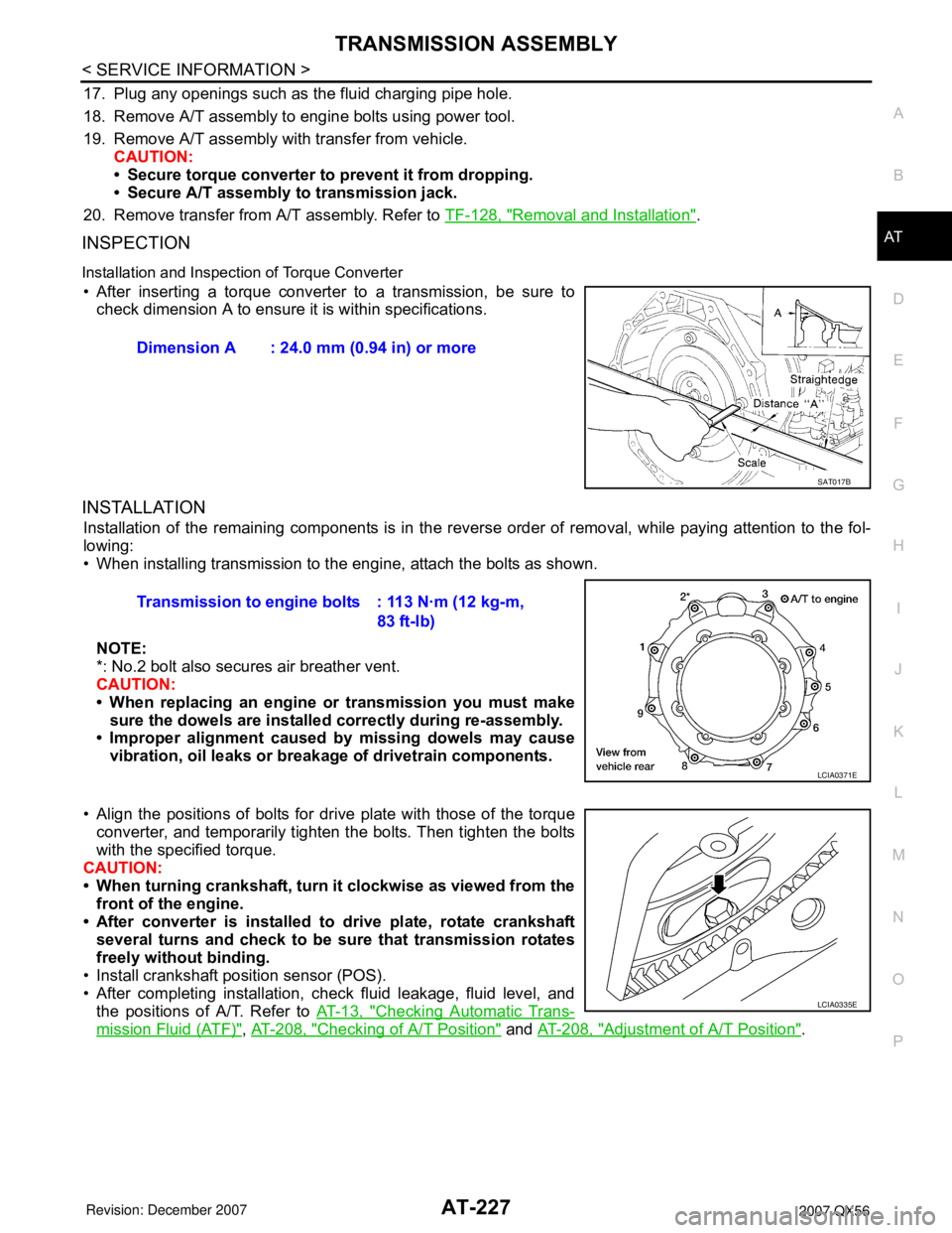
• After inserting a torque converter to a transmission, be sure to
check dimension A to ensure it is within specifications.
INSTALLATION
Installation of the remaining components is in the reverse order of removal, while paying attention to the fol-
lowing:
• When installing transmission to the engine, attach the bolts as shown.
NOTE:
*: No.2 bolt also secures air breather vent.
CAUTION:
• When replacing an engine or transmission you must make
sure the dowels are installed correctly during re-assembly.
• Improper alignment caused by missing dowels may cause
vibration, oil leaks or breakage of drivetrain components.
• Align the positions of bolts for drive plate with those of the torque
converter, and temporarily tighten the bolts. Then tighten the bolts
with the specified torque.
CAUTION:
• When turning crankshaft, turn it clockwise as viewed from the
front of the engine.
• After converter is installed to drive plate, rotate crankshaft
several turns and check to be sure that transmission rotates
freely without binding.
• Install crankshaft position sensor (POS).
• After completing installation, check fluid leakage, fluid level, and
the positions of A/T. Refer to AT-13, "
Checking Automatic Trans-
mission Fluid (ATF)", AT-208, "Checking of A/T Position" and AT-208, "Adjustment of A/T Position". Dimension A : 24.0 mm (0.94 in) or more
SAT017B
Transmission to engine bolts : 113 N·m (12 kg-m,
83 ft-lb)
LCIA0371E
LCIA0335E
Page 368 of 3061

AT-298
< SERVICE INFORMATION >
SERVICE DATA AND SPECIFICATIONS (SDS)
SERVICE DATA AND SPECIFICATIONS (SDS)
General SpecificationINFOID:0000000003532496
*1: Refer to MA-10, "Fluids and Lubricants".
Vehicle Speed When Shifting GearsINFOID:0000000003532497
NORMAL MODE
• At half throttle, the accelerator opening is 4/8 of the full opening.
TOW MODE
• At half throttle, the accelerator opening is 4/8 of the full opening.Applied model 2WD 4WD
Automatic transmission model RE5R05A
Transmission model code number 95X5B 95X5C
Stall torque ratio2.0: 1
Transmission gear ratio1st 3.827
2nd 2.368
3rd 1.520
4th 1.000
5th 0.834
Reverse 2.613
Recommended fluid Genuine NISSAN Matic J ATF *1
Fluid capacity 10.6 liter (11-1/4 US qt, 9-3/8 Imp qt)
CAUTION:
• Use only Genuine NISSAN Matic J ATF. Do not mix with other fluid.
• Using automatic transmission fluid other than Genuine NISSAN Matic J ATF will deteriorate in driveability and automatic
transmission durability, and may damage the automatic transmission, which is not covered by the warranty.
Final
gear
ratioThrottle positionVehicle speed km/h (MPH)
D
1 →D2D2 →D3D3 →D4D4 →D5D5 →D4D4 →D3D3 →D2D2 →D1
2.937Full throttle 70 - 74
(44 - 46)112 - 120
(70 - 75)176 - 186
(110 - 116)249 - 259
(155 - 161)245 - 255
(152 - 159)166 - 176
(103 - 110)100 - 108
(62 - 67)43 - 47
(27 - 30)
Half throttle 46 - 50
(28 - 31)74 - 82
(46 - 51)103 - 113
(64 - 70)135 - 145
(84 - 90)109 - 119
(68 - 74)69 - 79
(43 - 49)44 - 52
(27 - 32)11 - 1 5
(7 - 10)
3.357Full throttle 61 - 65
(38 - 41)97 - 105
(61 - 66)153 - 163
(95 - 102)236 - 246
(147 - 153)232 - 242
(144 - 151)143 - 153
(89 - 95)87 - 95
(54 - 59)43 - 47
(27 - 29)
Half throttle 41 - 45
(26 - 28)66 - 74
(41 - 46)89 - 99
(56 - 62)117 - 127
(73 - 79)95 - 105
(59 - 65)59 - 69
(37 - 43)38 - 46
(24 - 29)11 - 1 5
(7 - 10)
Final
gear
ratioThrottle positionVehicle speed km/h (MPH)
D
1 →D2D2 →D3D3 →D4D4 →D5D5 →D4D4 →D3D3 →D2D2 →D1
2.937Full throttle 70 - 74
(44 - 46)112 - 120
(70 - 75)176 - 186
(110 - 116)249 - 259
(155 - 161)245 - 255
(152 - 159)166 - 176
(103 - 110)100 - 108
(62 - 67)43 - 47
(27 - 30)
Half throttle 50 - 54
(31 - 34)81 - 89
(50 - 55)113 - 123
(70 - 76)135 - 145
(84 - 90)109 - 119
(68 - 74)68 - 78
(42 - 48)44 - 52
(27 - 32)11 - 1 5
(7 - 10)
3.357Full throttle 61 - 65
(38 - 41)97 - 105
(61 - 66)153 - 163
(95 - 102)236 - 246
(147 - 153)232 - 242
(144 - 151)143 - 153
(89 - 95)87 - 95
(54 - 59)43 - 47
(27 - 29)
Half throttle 43 - 47
(27 - 29)72 - 80
(45 - 50)98 - 108
(61 - 67)117 - 127
(73 - 79)95 - 105
(59 - 65)59 - 69
(37 - 43)37 - 45
(23 - 28)11 - 1 5
(7 - 10)