DTC INFINITI QX56 2007 Factory Service Manual
[x] Cancel search | Manufacturer: INFINITI, Model Year: 2007, Model line: QX56, Model: INFINITI QX56 2007Pages: 3061, PDF Size: 64.56 MB
Page 1673 of 3061

EC-590
< SERVICE INFORMATION >
DTC P2A00, P2A03 A/F SENSOR 1
Wiring Diagram
INFOID:0000000003532145
BANK 1
Specification data are reference values and are measured between each terminal and ground.
Pulse signal is measured by CONSULT-II.
CAUTION:
BBWA2790E
Page 1674 of 3061

DTC P2A00, P2A03 A/F SENSOR 1
EC-591
< SERVICE INFORMATION >
C
D
E
F
G
H
I
J
K
L
MA
EC
N
P O
Do not use ECM ground terminals when measuring input/output voltage. Doing so may result in dam-
age to the ECM's transistor. Use a ground other than ECM terminals, such as the ground.
: Average voltage for pulse signal (Actual pulse signal can be confirmed by oscilloscope.)TER-
MI-
NAL
NO.WIRE
COLORITEM CONDITION DATA (DC Voltage)
2 LG/B A/F sensor 1 heater (bank 1)[Engine is running]
•Warm-up condition
• Idle speed
(More than 140 seconds after starting en-
gine)Approximately 2.9 - 8.8V
35 BR/R A/F sensor 1 (bank 1)[Engine is running]
•Warm-up condition
• Engine speed: 2,000 rpmApproximately 1.8V
Output voltage varies with air fuel
ratio.
56 BR/G A/F sensor 1 (bank 1)[Ignition switch: ON]Approximately 2.2V
PBIA8148J
Page 1675 of 3061

EC-592
< SERVICE INFORMATION >
DTC P2A00, P2A03 A/F SENSOR 1
BANK 2
Specification data are reference values and are measured between each terminal and ground.
Pulse signal is measured by CONSULT-II.
CAUTION:
Do not use ECM ground terminals when measuring input/output voltage. Doing so may result in dam-
age to the ECM's transistor. Use a ground other than ECM terminals, such as the ground.
BBWA2789E
Page 1676 of 3061

DTC P2A00, P2A03 A/F SENSOR 1
EC-593
< SERVICE INFORMATION >
C
D
E
F
G
H
I
J
K
L
MA
EC
N
P O
: Average voltage for pulse signal (Actual pulse signal can be confirmed by oscilloscope.)
Diagnosis ProcedureINFOID:0000000003532146
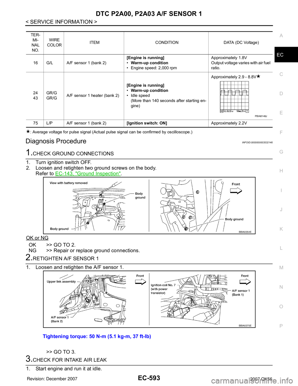
1.CHECK GROUND CONNECTIONS
1. Turn ignition switch OFF.
2. Loosen and retighten two ground screws on the body.
Refer to EC-143, "
Ground Inspection".
OK or NG
OK >> GO TO 2.
NG >> Repair or replace ground connections.
2.RETIGHTEN A/F SENSOR 1
1. Loosen and retighten the A/F sensor 1.
>> GO TO 3.
3.CHECK FOR INTAKE AIR LEAK
1. Start engine and run it at idle.
TER-
MI-
NAL
NO.WIRE
COLORITEM CONDITION DATA (DC Voltage)
16 G/L A/F sensor 1 (bank 2)[Engine is running]
•Warm-up condition
• Engine speed: 2,000 rpmApproximately 1.8V
Output voltage varies with air fuel
ratio.
24
43GR/G
GR/GA/F sensor 1 heater (bank 2)[Engine is running]
•Warm-up condition
• Idle speed
(More than 140 seconds after starting en-
gine)Approximately 2.9 - 8.8V
75 L/P A/F sensor 1 (bank 2)[Ignition switch: ON]Approximately 2.2V
PBIA8148J
BBIA0354E
Tightening torque: 50 N-m (5.1 kg-m, 37 ft-lb)
BBIA0375E
Page 1677 of 3061

EC-594
< SERVICE INFORMATION >
DTC P2A00, P2A03 A/F SENSOR 1
2. Listen for an intake air leak after the mass air flow sensor.
OK or NG
OK >> GO TO 4.
NG >> Repair or replace.
4.CLEAR THE SELF-LEARNING DATA
With CONSULT-II
1. Start engine and warm it up to normal operating temperature.
2. Select “SELF-LEARNING CONT” in “WORK SUPPORT” mode with CONSULT-II.
3. Clear the self-learning control coefficient by touching “CLEAR”.
4. Run engine for at least 10 minutes at idle speed.
Is the 1st trip DTC P0171, P0172, P0174 or P0175 detected?
Is it difficult to start engine?
Without CONSULT-II
1. Start engine and warm it up to normal operating temperature.
2. Turn ignition switch OFF.
3. Disconnect mass air flow sensor harness connector.
4. Restart engine and let it idle for at least 5 seconds.
5. Stop engine and reconnect mass air flow sensor harness con-
nector.
6. Make sure DTC P0102 is displayed.
7. Erase the DTC memory. Refer to EC-49, "
Emission-related
Diagnostic Information".
8. Make sure DTC P0000 is displayed.
9. Run engine for at least 10 minutes at idle speed.
Is the 1st trip DTC P0171, P0172, P0174 or P0175 detected?
Is it difficult to start engine?
Ye s o r N o
Yes >> Perform trouble diagnosis for DTC P0171, P0174 or P0172, P0175. Refer to EC-292 or EC-301.
No >> GO TO 5.
5.CHECK HARNESS CONNECTOR
1. Turn ignition switch OFF.
2. Disconnect A/F sensor 1 harness connector.
3. Check harness connector for water.
OK or NG
OK >> GO TO 6.
NG >> Repair or replace harness connector.
SEF968Y
BBIA0368E
Water should not exit.
BBIA0376E
Page 1678 of 3061

DTC P2A00, P2A03 A/F SENSOR 1
EC-595
< SERVICE INFORMATION >
C
D
E
F
G
H
I
J
K
L
MA
EC
N
P O
6.CHECK A/F SENSOR 1 POWER SUPPLY CIRCUIT
1. Turn ignition switch ON.
2. Check voltage between A/F sensor 1 terminal 4 and ground with
CONSULT-II or tester.
OK or NG
OK >> GO TO 8.
NG >> GO TO 7.
7.DETECT MALFUNCTIONING PART
Check the following.
• Harness connectors E5, F14
• IPDM E/R harness connector E119
• 15A fuse
• Harness for open or short between A/F sensor 1 and fuse
>> Repair or replace harness or connectors.
8.CHECK A/F SENSOR 1 INPUT SIGNAL CIRCUIT FOR OPEN AND SHORT
1. Turn ignition switch OFF.
2. Disconnect ECM harness connector.
3. Check harness continuity between A/F sensor 1 terminal and ECM terminal as follows.
Refer to Wiring Diagram.
4. Check harness continuity between the following terminals and ground.
Refer to Wiring Diagram.
5. Also check harness for short to power.
OK or NG
OK >> GO TO 9.
NG >> Repair open circuit or short to ground or short to power in harness or connectors.
9.CHECK A/F SENSOR 1 HEATER
Refer to EC-168, "
Component Inspection".
OK or NG
Voltage: Battery voltage
PBIB3308E
A/F sensor 1 terminal ECM terminal
Bank1135
256
Bank 2116
275
Continuity should exist.
Bank 1 Bank 2
A/F sensor 1 terminal ECM terminal A/F sensor 1 terminal ECM terminal
135116
256275
Continuity should not exist.
Page 1679 of 3061

EC-596
< SERVICE INFORMATION >
DTC P2A00, P2A03 A/F SENSOR 1
OK >> GO TO 10.
NG >> GO TO 11.
10.CHECK INTERMITTENT INCIDENT
Perform EC-138
.
OK or NG
OK >> GO TO 11.
NG >> Repair or replace.
11 .REPLACE AIR FUEL RATIO (A/F) SENSOR 1
Replace malfunctioning air fuel ratio (A/F) sensor 1.
CAUTION:
• Discard any A/F sensor which has been dropped from a height of more than 0.5 m (19.7 in) onto a
hard surface such as a concrete floor; use a new one.
• Before installing new A/F sensor, clean exhaust system threads using Oxygen Sensor Thread
Cleaner tool J-43897-18 or J-43897-12 and approved anti-seize lubricant.
>> GO TO 12.
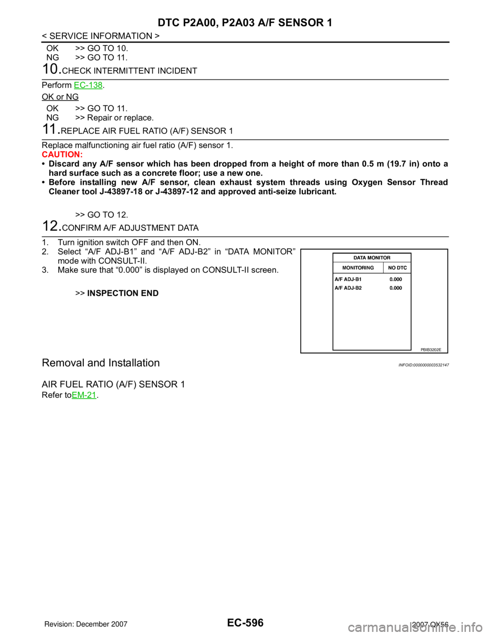
12.CONFIRM A/F ADJUSTMENT DATA
1. Turn ignition switch OFF and then ON.
2. Select “A/F ADJ-B1” and “A/F ADJ-B2” in “DATA MONITOR”
mode with CONSULT-II.
3. Make sure that “0.000” is displayed on CONSULT-II screen.
>>INSPECTION END
Removal and InstallationINFOID:0000000003532147
AIR FUEL RATIO (A/F) SENSOR 1
Refer toEM-21.
PBIB3202E
Page 1688 of 3061

ASCD INDICATOR
EC-605
< SERVICE INFORMATION >
C
D
E
F
G
H
I
J
K
L
MA
EC
N
P O
OK or NG
OK >>INSPECTION END
NG >> GO TO 2.
2.CHECK DTC
Check that DTC U1000 or U1001 is not displayed.
OK or NG
OK >> GO TO 3.
NG >> Perform trouble diagnosis for DTC U1000, U1001. Refer to EC-145
.
3.CHECK COMBINATION METER FUNCTION
Refer to DI-5
.
OK or NG
OK >> GO TO 4.
NG >> Go to DI-5
.
4.CHECK INTERMITTENT INCIDENT
Refer to EC-138
.
>>INSPECTION END
ASCD INDICATOR CONDITION SPECIFICATION
CRUISE LAMP • Ignition switch: ON• MAIN switch: Pressed at the 1st
time → at the 2nd timeON → OFF
SET LAMP• MAIN switch: ON
• When vehicle speed is between
40 km/h (25 MPH) and 144 km/h
(89 MPH)•ASCD: Operating ON
• ASCD: Not operating OFF
Page 1705 of 3061

EC-622
< SERVICE INFORMATION >
ICC BRAKE SWITCH
Without CONSULT-II
Check voltage between ECM terminal 101 and ground under the fol-
lowing conditions.
OK or NG
OK >>INSPECTION END
NG >> GO TO 10.
3.CHECK DTC WITH ICC UNIT
Refer to ACS-34
.
OK or NG
OK >> GO TO 4.
NG >> Repair or replace.
4.CHECK ICC BRAKE HOLD RELAY POWER SUPPLY CIRCUIT
1. Turn ignition switch OFF.
2. Disconnect ICC brake hold relay.
3. Turn ignition switch ON.
4. Check voltage between ICC brake hold relay terminal 4 and
ground with CONSULT-II or tester.
OK or NG
OK >> GO TO 6.
NG >> GO TO 5.
5.DETECT MALFUNCTIONING PART
Check the following.
• Harness connectors M31, E152
• Fuse block (J/B) connector M4
• 10A fuse
• Harness for open or short between ICC brake hold relay and fuse
>> Repair open circuit or short to ground or short to power in harness or connectors.
CONDITION VOLTAGE
Brake pedal: Fully released Approximately 0V
Brake pedal: Slightly depressed Battery voltage
PBIB1537E
BBIA0471E
Voltage: Battery voltage
MBIB0059E
Page 1825 of 3061

CAMSHAFTEM-55
< SERVICE INFORMATION >
C
DE
F
G H
I
J
K L
M A
EM
NP
O
5. Install the camshaft sprockets using the following procedure:
• A: LH bank shown
a. Install the camshaft sprockets aligning them with the matching marks painted on the timing chain (B) and the camshaft sprock-
ets (C) before removal. Align the camshaft sprocket key groove
with the dowel pin on the camshaft front edge at the same time.
Then temporarily tighten camshaft sprocket bolts.
• Install the intake camshaft sprocket (VTC) (A) and exhaust
camshaft sprockets (B) by select ively using the groove of the
dowel pin according to the bank. (Common part used for both
exhaust banks.)
NOTE:
Use the groove marked "R" for RH bank and "L" for LH bank.
b. Lock the hexagonal part of the camshaft in the same way as for removal, and tighten the camshaft sprocket bolts.
c. Check again that the timing alignment mark on the timing chain and on each sprocket are aligned.
6. Install the chain tensioner using the following procedure: NOTE:
LH is shown.
a. Install the chain tensioner. • Compress the plunger and hold it using a stopper pin wheninstalling.
• Loosen the slack guide side timing chain by rotating the cam- shaft hexagonal part if mounting space is small.
b. Remove the stopper pin and release the plunger, and then apply tension to the timing chain.
c. Install the chain tensioner cover onto the front cover. • Apply liquid gasket as shown.
Use Genuine RTV Silicone Seal ant or equivalent. Refer to
GI-45, "
Recommended Chemical Product and Sealant".
7. Check and adjust valve clearances. Refer to EM-56, "
Va l v e
Clearance".
8. Installation of the remaining components is in the reverse order of removal.
Inspection after InstallationINFOID:0000000003531535
INSPECTION OF CAMSHAFT SPROCKET (INT) OIL GROOVE
CAUTION:
• Perform this inspection only when DTC P0011 is de tected in self-diagnostic results of CONSULT II
and it is directed according to inspect ion procedure of EC section. Refer to EC-159, "
Component
Inspection".
• Check when engine is cold so as to pr event burns from any splashing engine oil.
1. Check engine oil level. Refer to LU-8, "
Inspection".
AWBIA0152ZZ
AWBIA0151ZZ
Chain tensioner bolts : 6.9 N·m (0.70 kg-m, 61 in-lb)
Tensioner cover bolts : 9.0 N·m (0.92 kg-m, 80 in-lb)KBIA2479E
KBIA2547E