cooling INFINITI QX56 2007 Factory Service Manual
[x] Cancel search | Manufacturer: INFINITI, Model Year: 2007, Model line: QX56, Model: INFINITI QX56 2007Pages: 3061, PDF Size: 64.56 MB
Page 1 of 3061
-1
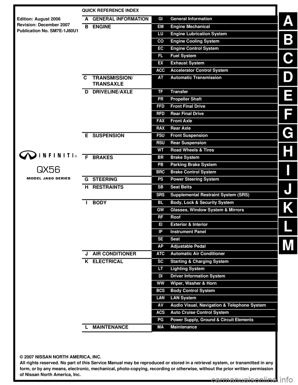
QUICK REFERENCE INDEX
AGENERAL INFORMATIONGIGeneral Information
BENGINEEMEngine Mechanical
LUEngine Lubrication System
COEngine Cooling System
ECEngine Control System
FLFuel System
EXExhaust System
ACCAccelerator Control System
CTRANSMISSION/
TRANSAXLEATAutomatic Transmission
DDRIVELINE/AXLETFTransfer
PRPropeller Shaft
FFDFront Final Drive
RFDRear Final Drive
FAXFront Axle
RAXRear Axle
ESUSPENSIONFSUFront Suspension
RSURear Suspension
WTRoad Wheels & Tires
FBRAKESBRBrake System
PBParking Brake System
BRCBrake Control System
GSTEERINGPSPower Steering System
HRESTRAINTSSBSeat Belts
SRSSupplemental Restraint System (SRS)
IBODYBLBody, Lock & Security System
GWGlasses, Window System & Mirrors
RFRoof
EIExterior & Interior
IPInstrument Panel
SESeat
APAdjustable Pedal
JAIR CONDITIONERATCAutomatic Air Conditioner
KELECTRICALSCStarting & Charging System
LTLighting System
DIDriver Information System
WWWiper, Washer & Horn
BCSBody Control System
LANLAN System
AVAudio Visual, Navigation & Telephone System
ACSAuto Cruise Control System
PGPower Supply, Ground & Circuit Elements
LMAINTENANCEMAMaintenance
Edition: August 2006
Revision: December 2007
Publication No. SM7E-1J60U1
B
D
© 2007 NISSAN NORTH AMERICA, INC.
All rights reserved. No part of this Service Manual may be reproduced or stored in a retrieval system, or transmitted in any
form, or by any means, electronic, mechanical, photo-copying, recording or otherwise, without the prior written permission
of Nissan North America, Inc.
A
C
E
F
G
H
I
J
K
L
M
Page 8 of 3061
QUICK REFERENCE CHART: QX56
2007
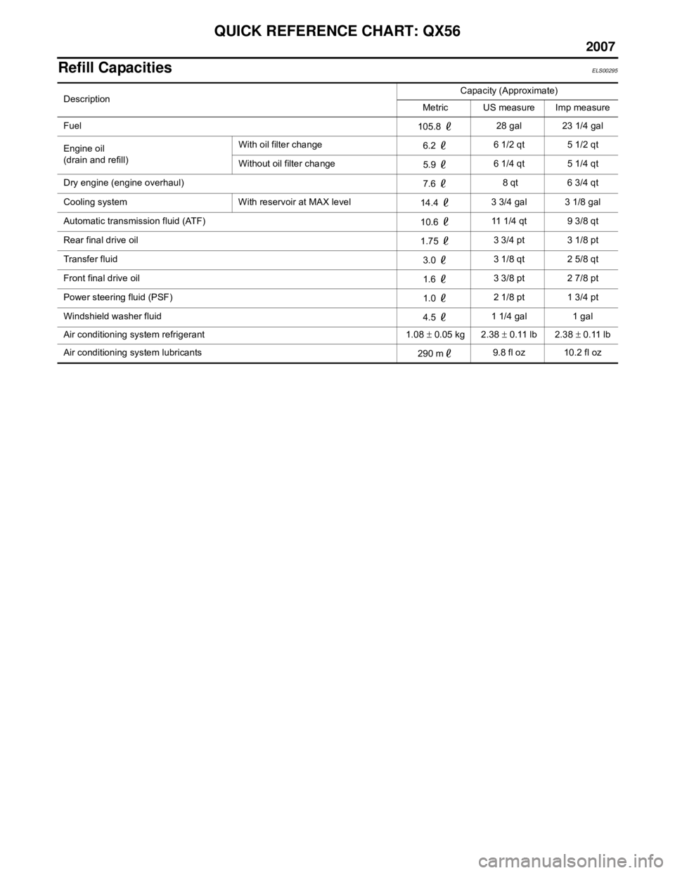
Refill CapacitiesELS00295
DescriptionCapacity (Approximate)
Metric US measure Imp measure
Fuel 105.8 28 gal 23 1/4 gal
Engine oil
(drain and refill) With oil filter change
6.2 6 1/2 qt 5 1/2 qt
Without oil filter change 5.9 6 1/4 qt 5 1/4 qt
Dry engine (engine overhaul) 7.6 8 qt 6 3/4 qt
Cooling system With reservoir at MAX level 14.4 3 3/4 gal 3 1/8 gal
Automatic transmission fluid (ATF) 10.6 11 1/4 qt 9 3/8 qt
Rear final drive oil 1.75 3 3/4 pt 3 1/8 pt
Transfer fluid 3.0 3 1/8 qt 2 5/8 qt
Front final drive oil 1.6 3 3/8 pt 2 7/8 pt
Power steering fluid (PSF) 1.0 2 1/8 pt 1 3/4 pt
Windshield washer fluid 4.5 1 1/4 gal 1 gal
Air conditioning system refrigerant 1.08 ± 0.05 kg 2.38 ± 0.11 lb 2.38 ± 0.11 lb
Air conditioning system lubricants 290 m9.8 fl oz 10.2 fl oz
Page 61 of 3061
![INFINITI QX56 2007 Factory Service Manual ACS-48
< SERVICE INFORMATION >[ICC]
TROUBLE DIAGNOSIS FOR SELF-DIAGNOSTIC ITEMS
Are “DTC 11 CONTROL UNIT” or “DTC 20 CAN COMM CIRCUIT” item indicated in self-diagnosis display
item?
YES or NO
INFINITI QX56 2007 Factory Service Manual ACS-48
< SERVICE INFORMATION >[ICC]
TROUBLE DIAGNOSIS FOR SELF-DIAGNOSTIC ITEMS
Are “DTC 11 CONTROL UNIT” or “DTC 20 CAN COMM CIRCUIT” item indicated in self-diagnosis display
item?
YES or NO](/img/42/57029/w960_57029-60.png)
ACS-48
< SERVICE INFORMATION >[ICC]
TROUBLE DIAGNOSIS FOR SELF-DIAGNOSTIC ITEMS
Are “DTC 11 CONTROL UNIT” or “DTC 20 CAN COMM CIRCUIT” item indicated in self-diagnosis display
item?
YES or NO
YES >> GO TO applicable item inspection. Refer to ACS-36, "DTC 11 CONTROL UNIT", and ACS-37,
"DTC 20 CAN COMM CIRCUIT".
NO >> • Replace ICC sensor and adjust laser beam aiming. Refer to ACS-55, "
ICC Sensor".
• Erase DTC and perform ICC system running test. Refer to ACS-9, "
ICC System Running Test".
Then perform self-diagnosis of ICC system again.
DTC 104 LASER AIMING INCMPINFOID:0000000003533811
1.DIAGNOSTIC CHECK
1. Adjust laser beam aiming. Refer to ACS-12
. Erase DTC and perform ICC system running test. Refer to
ACS-9, "
ICC System Running Test".
2. Perform self-diagnosis of ICC system. Is “DTC 104 LASER AIMING INCMP” indicated?
CAUTION:
Ensure that laser beam aiming apparatus is set up accurately.
YES or NO
YES >> • Replace ICC sensor and adjust laser beam aiming. Refer to ACS-55, "ICC Sensor".
• Erase DTC and perform ICC system running test. Refer to ACS-9, "
ICC System Running Test".
Then perform self-diagnosis of ICC system again.
NO >> Inspection end.
DTC 107 LASER COMM FAILINFOID:0000000003533812
1.DIAGNOSTIC CHECK
Is “DTC 11 CONTROL UNIT” or “DTC 20 CAN COMM CIRCUIT” indicated in the self-diagnosis display item?
YES or NO
YES >> GO TO applicable item inspection. Refer to ACS-36, "DTC 11 CONTROL UNIT" , or ACS-37,
"DTC 20 CAN COMM CIRCUIT".
NO >> • Replace ICC sensor and adjust laser beam aiming. Refer to ACS-55, "
ICC Sensor".
• Erase DTC and perform ICC system running test. Refer to ACS-9, "
ICC System Running Test".
Then perform self-diagnosis of ICC system again.
DTC 109 LASER HIGH TEMPINFOID:0000000003533813
1.CHECK SYMPTOM
Is cooling system malfunctioning?
YES or NO
YES >> • Repair cooling system.
• Erase DTC and perform ICC system running test. Refer to ACS-9, "
ICC System Running Test".
Then perform self-diagnosis of ICC system again.
NO >> • Replace ICC sensor and adjust laser beam aiming. Refer to ACS-55, "
ICC Sensor".
• Erase DTC, then perform ICC system running test. Refer to ACS-9, "
ICC System Running Test".
Then perform self-diagnosis of ICC system again.
Page 79 of 3061
PRECAUTIONS
AT-9
< SERVICE INFORMATION >
D
E
F
G
H
I
J
K
L
MA
B
AT
N
O
P
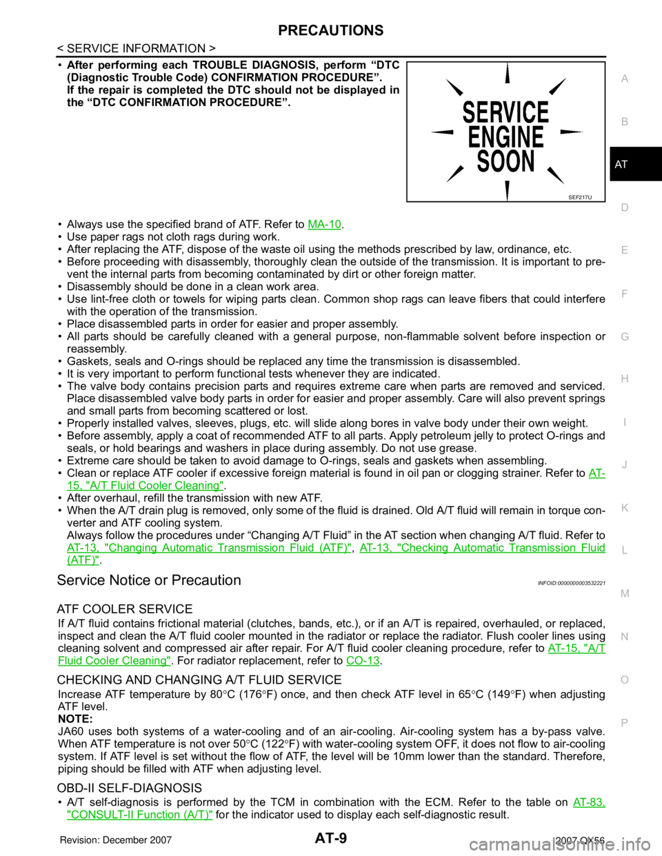
•After performing each TROUBLE DIAGNOSIS, perform “DTC
(Diagnostic Trouble Code) CONFIRMATION PROCEDURE”.
If the repair is completed the DTC should not be displayed in
the “DTC CONFIRMATION PROCEDURE”.
• Always use the specified brand of ATF. Refer to MA-10
.
• Use paper rags not cloth rags during work.
• After replacing the ATF, dispose of the waste oil using the methods prescribed by law, ordinance, etc.
• Before proceeding with disassembly, thoroughly clean the outside of the transmission. It is important to pre-
vent the internal parts from becoming contaminated by dirt or other foreign matter.
• Disassembly should be done in a clean work area.
• Use lint-free cloth or towels for wiping parts clean. Common shop rags can leave fibers that could interfere
with the operation of the transmission.
• Place disassembled parts in order for easier and proper assembly.
• All parts should be carefully cleaned with a general purpose, non-flammable solvent before inspection or
reassembly.
• Gaskets, seals and O-rings should be replaced any time the transmission is disassembled.
• It is very important to perform functional tests whenever they are indicated.
• The valve body contains precision parts and requires extreme care when parts are removed and serviced.
Place disassembled valve body parts in order for easier and proper assembly. Care will also prevent springs
and small parts from becoming scattered or lost.
• Properly installed valves, sleeves, plugs, etc. will slide along bores in valve body under their own weight.
• Before assembly, apply a coat of recommended ATF to all parts. Apply petroleum jelly to protect O-rings and
seals, or hold bearings and washers in place during assembly. Do not use grease.
• Extreme care should be taken to avoid damage to O-rings, seals and gaskets when assembling.
• Clean or replace ATF cooler if excessive foreign material is found in oil pan or clogging strainer. Refer to AT-
15, "A/T Fluid Cooler Cleaning".
• After overhaul, refill the transmission with new ATF.
• When the A/T drain plug is removed, only some of the fluid is drained. Old A/T fluid will remain in torque con-
verter and ATF cooling system.
Always follow the procedures under “Changing A/T Fluid” in the AT section when changing A/T fluid. Refer to
AT-13, "
Changing Automatic Transmission Fluid (ATF)", AT-13, "Checking Automatic Transmission Fluid
(ATF)".
Service Notice or PrecautionINFOID:0000000003532221
ATF COOLER SERVICE
If A/T fluid contains frictional material (clutches, bands, etc.), or if an A/T is repaired, overhauled, or replaced,
inspect and clean the A/T fluid cooler mounted in the radiator or replace the radiator. Flush cooler lines using
cleaning solvent and compressed air after repair. For A/T fluid cooler cleaning procedure, refer to AT-15, "
A/T
Fluid Cooler Cleaning". For radiator replacement, refer to CO-13.
CHECKING AND CHANGING A/T FLUID SERVICE
Increase ATF temperature by 80°C (176°F) once, and then check ATF level in 65°C (149°F) when adjusting
ATF level.
NOTE:
JA60 uses both systems of a water-cooling and of an air-cooling. Air-cooling system has a by-pass valve.
When ATF temperature is not over 50°C (122°F) with water-cooling system OFF, it does not flow to air-cooling
system. If ATF level is set without the flow of ATF, the level will be 10mm lower than the standard. Therefore,
piping should be filled with ATF when adjusting level.
OBD-II SELF-DIAGNOSIS
• A/T self-diagnosis is performed by the TCM in combination with the ECM. Refer to the table on AT-83,
"CONSULT-II Function (A/T)" for the indicator used to display each self-diagnostic result.
SEF217U
Page 85 of 3061
A/T FLUID
AT-15
< SERVICE INFORMATION >
D
E
F
G
H
I
J
K
L
MA
B
AT
N
O
P
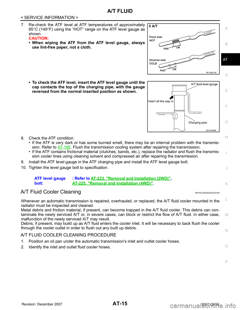
7. Re-check the ATF level at ATF temperatures of approximately
65°C (149°F) using the “HOT” range on the ATF level gauge as
shown.
CAUTION:
• When wiping the ATF from the ATF level gauge, always
use lint-free paper, not a cloth.
• To check the ATF level, insert the ATF level gauge until the
cap contacts the top of the charging pipe, with the gauge
reversed from the normal inserted position as shown.
8. Check the ATF condition.
• If the ATF is very dark or has some burned smell, there may be an internal problem with the transmis-
sion. Refer to AT-165
. Flush the transmission cooling system after repairing the transmission.
• If the ATF contains frictional material (clutches, bands, etc.), replace the radiator and flush the transmis-
sion cooler lines using cleaning solvent and compressed air after repairing the transmission.
9. Install the ATF level gauge in the ATF charging pipe and install the ATF level gauge bolt.
10. Tighten the level gauge bolt to specification.
A/T Fluid Cooler CleaningINFOID:0000000003532226
Whenever an automatic transmission is repaired, overhauled, or replaced, the A/T fluid cooler mounted in the
radiator must be inspected and cleaned.
Metal debris and friction material, if present, can become trapped in the A/T fluid cooler. This debris can con-
taminate the newly serviced A/T or, in severe cases, can block or restrict the flow of A/T fluid. In either case,
malfunction of the newly serviced A/T may result.
Debris, if present, may build up as A/T fluid enters the cooler inlet. It will be necessary to back flush the cooler
through the cooler outlet in order to flush out any built up debris.
A/T FLUID COOLER CLEANING PROCEDURE
1. Position an oil pan under the automatic transmission's inlet and outlet cooler hoses.
2. Identify the inlet and outlet fluid cooler hoses.
WLIA0014E
SCIA1684E
ATF level gauge
bolt:: Refer to AT-223, "Removal and Installation (2WD)",
AT-225, "
Removal and Installation (4WD)".
Page 108 of 3061

AT-38
< SERVICE INFORMATION >
A/T CONTROL SYSTEM
FUNCTION OF PRESSURE SWITCH
Pilot valve AAdjusts the line pressure and produces the constant pressure (pilot pressure) required
for line pressure control, shift change control, and lock-up control.
Pilot valve BAdjusts the line pressure and produces the constant pressure (pilot pressure) required
for shift change control.
Low coast brake switching valve During engine braking, supplies the line pressure to the low coast brake reducing valve.
Low coast brake reducing valveWhen the low coast brake is coupled, adjusts the line pressure to the optimum pressure
(low coast brake pressure) and supplies it to the low coast brake.
N-R accumulator Produces the stabilizing pressure for when N-R is selected.
Direct clutch piston switching valve Operates in 4th gear and switches the direct clutch coupling capacity.
High and low reverse clutch control valveWhen the high and low reverse clutch is coupled, adjusts the line pressure to the opti-
mum pressure (high and low reverse clutch pressure) and supplies it to the high and low
reverse clutch. (In 1st, 3rd, 4th and 5th gears, adjusts the clutch pressure.)
Input clutch control valveWhen the input clutch is coupled, adjusts the line pressure to the optimum pressure (in-
put clutch pressure) and supplies it to the input clutch. (In 4th and 5th gears, adjusts the
clutch pressure.)
Direct clutch control valveWhen the direct clutch is coupled, adjusts the line pressure to the optimum pressure (di-
rect clutch pressure) and supplies it to the direct clutch. (In 2nd, 3rd, and 4th gears, ad-
justs the clutch pressure.)
TCC control valve
TCC control plug
TCC control sleeveSwitches the lock-up to operating or released. Also, by performing the lock-up operation
transiently, lock-up smoothly.
Torque converter lubrication valveOperates during lock-up to switch the torque converter, cooling, and lubrication system
oil path.
Cool bypass valve Allows excess oil to bypass cooler circuit without being fed into it.
Line pressure relief valve Discharges excess oil from line pressure circuit.
N-D accumulator Produces the stabilizing pressure for when N-D is selected.
Manual valveSends line pressure to each circuit according to the select position. The circuits to which
the line pressure is not sent drain. Name Function
Name Function
Pressure switch 1 (FR/B)Detects any malfunction in the front brake hydraulic pressure. When it detects any mal-
function, it puts the system into fail-safe mode.
Pressure switch 2 (LC/B)Detects any malfunction in the low coast brake hydraulic pressure. When it detects any
malfunction, it puts the system into fail-safe mode.
Pressure switch 3 (I/C)Detects any malfunction in the input clutch hydraulic pressure. When it detects any mal-
function, it puts the system into fail-safe mode.
Pressure switch 5 (D/C)Detects any malfunction in the direct clutch hydraulic pressure. When it detects any mal-
function, it puts the system into fail-safe mode.
Pressure switch 6 (HLR/C)Detects any malfunction in the high and low reverse clutch hydraulic pressure. When it
detects any malfunction, it puts the system into fail-safe mode.
Page 371 of 3061

ATC-1
AIR CONDITIONER
C
DE
F
G H
I
K L
M
SECTION AT C
A
B
AT C
N
O P
CONTENTS
AUTOMATIC AIR CONDITIONER
SERVICE INFORMATION .. ..........................3
PRECAUTIONS .............................................. .....3
Precaution for Supplemental Restraint System
(SRS) "AIR BAG" and "SEAT BELT PRE-TEN-
SIONER" ............................................................. ......
3
Precaution for Working with HFC-134a (R-134a) ......3
Contaminated Refrigerant .........................................3
General Refrigerant Precaution ................................4
Precaution for Leak Detection Dye ...........................4
A/C Identification Label .............................................4
Precaution for Refrigerant Connection ......................4
Precaution for Service of Compressor ................ ......9
Precaution for Service Equipment ....................... ......9
PREPARATION ..................................................12
Special Service Tool ........................................... ....12
HFC-134a (R-134a) Service Tool and Equipment ....12
Commercial Service Tool ........................................14
REFRIGERATION SYSTEM ..............................16
Refrigerant Cycle ................................................ ....16
Refrigerant System Protection ................................16
Component Part Location ................................... ....17
OIL ......................................................................20
Maintenance of Oil Quantity in Compressor ....... ....20
AIR CONDITIONER CONTROL .........................22
Description .......................................................... ....22
Operation ................................................................22
Description of Control System .................................23
Control Operation ....................................................24
Discharge Air Flow ..................................................26
System Description (Front) .....................................27
System Description (Rear) .................................. ....28
CAN Communication System Description ...............29
TROUBLE DIAGNOSIS .....................................30
CONSULT-II Function (HVAC) ............................ ....30
CONSULT-II Function (BCM) ..................................31
How to Perform Trouble Diagnosis for Quick and
Accurate Repair ................................................... ....
32
Component Parts and Harness Connector Loca-
tion ...........................................................................
32
Schematic ................................................................36
Wiring Diagram - A/C,A - .........................................37
Front Air Control Terminal and Reference Value ....47
A/C System Self-Diagnosis Function .......................48
Operational Check (Front) ................................... ....50
Operational Check (Rear) ........................................51
Power Supply and Ground Circuit for Front Air
Control ................................................................. ....
52
Mode Door Motor Circuit .........................................54
Air Mix Door Motor Circuit ................................... ....59
Intake Door Motor Circuit .........................................70
Defroster Door Motor Circuit ....................................74
Front Blower Motor Circuit .......................................78
Rear Blower Motor Circuit ................................... ....85
Rear Air Control Circuit ............................................93
Magnet Clutch Circuit ..............................................96
Insufficient Cooling ................................................100
Insufficient Heating ................................................108
Noise .....................................................................109
Self-Diagnosis .......................................................111
Memory Function ...................................................112
Water Valve Circuit ................................................113
Ambient Sensor Circuit ..........................................114
In-vehicle Sensor Circuit ........................................116
Optical Sensor Circuit ............................................119
Intake Sensor Circuit .............................................120
CONTROL UNIT ..............................................123
Removal and Installation .......................................123
AMBIENT SENSOR ........................................124
Removal and Installation .......................................124
IN-VEHICLE SENSOR ....................................125
Removal and Installation .......................................125
OPTICAL SENSOR .........................................126
Page 372 of 3061

ATC-2
Removal and Installation .......................................126
INTAKE SENSOR ............................................127
Removal and Installation ..................................... ..127
BLOWER MOTOR ...........................................128
Component .......................................................... ..128
Removal and Installation .......................................128
IN-CABIN MICROFILTER ................................130
Removal and Installation ..................................... ..130
HEATER & COOLING UNIT ASSEMBLY .......132
Component .......................................................... ..132
Removal and Installation .......................................133
HEATER CORE ...............................................135
Component .......................................................... ..135
Removal and Installation .......................................136
DEFROSTER DOOR MOTOR .........................138
Removal and Installation ..................................... ..138
INTAKE DOOR MOTOR ..................................139
Removal and Installation ..................................... ..139
MODE DOOR MOTOR ....................................140
Removal and Installation ..................................... ..140
AIR MIX DOOR MOTOR ..................................141
Component .......................................................... ..141
Removal and Installation .......................................141
VARIABLE BLOWER CONTROL ...................143
Removal and Installation ..................................... ..143
REAR BLOWER MOTOR RESISTOR ............144
Removal and Installation ..................................... ..144
DUCTS AND GRILLES ....................................145
Component .......................................................... .145
Removal and Installation .......................................148
REFRIGERANT LINES ................................... ..150
HFC-134a (R-134a) Service Procedure ............... .150
Component ...........................................................152
Removal and Installation for Compressor .............154
Removal and Installation for Compressor Clutch ..155
Removal and Installation for Low-Pressure Flexi-
ble Hose ............................................................... .
158
Removal and Installation for High-pressure Flexi-
ble Hose ............................................................... .
158
Removal and Installation for High-pressure Pipe ..158
Removal and Installation for Low-Pressure Pipe ..159
Removal and Installation for Rear High- and Low-
Pressure A/C and Heater Core Pipes .................. .
159
Removal and Installation for Underfloor Rear
High- and Low-Pressure A/C and Heater Core
Pipes .................................................................... .
160
Removal and Installation for Refrigerant Pressure
Sensor .................................................................. .
161
Removal and Installation for Condenser ...............161
Removal and Installation for Front Evaporator .....163
Removal and Installation for Rear Evaporator ......164
Removal and Installation for Front Expansion
Valve .....................................................................
165
Removal and Installation for Rear Expansion
Valve .................................................................... .
165
Checking of Refrigerant Leaks ..............................166
Checking System for Leaks Using the Fluorescent
Dye Leak Detector ................................................
166
Dye Injection .........................................................166
Electronic Refrigerant Leak Detector ....................167
SERVICE DATA AND SPECIFICATIONS
(SDS) ................................................................
170
Service Data and Specification (SDS) ..................170
Page 374 of 3061

ATC-4
< SERVICE INFORMATION >
PRECAUTIONS
not have dedicated recovery equipment, you may contact a local refrigerant product retailer for available ser-
vice. This refrigerant must be disposed of in acco rdance with all federal and local regulations. In addition,
replacement of all refrigerant system components on the vehicle is recommended.
• If the vehicle is within the warranty period, the air conditioner warranty is void. Please contact NISSAN Cus-
tomer Affairs for further assistance.
General Refrigerant PrecautionINFOID:0000000003533220
WARNING:
• Do not release refrigerant into th e air. Use approved recovery/recycling equipment to capture the
refrigerant every time an air conditioning system is discharged.
• Always wear eye and hand protection (goggles and gloves) when working with any refrigerant or air
conditioning system.
• Do not store or heat refrigerant containers above 52 °C (125 °F).
• Do not heat a refrigerant container with an open flame; if container warming is required, place the
bottom of the container in a warm pail of water.
• Do not intentionally drop, puncture, or incinerate refrigerant containers.
• Keep refrigerant away from open flames: poisonou s gas will be produced if refrigerant burns.
• Refrigerant will displace oxygen, therefore be certa in to work in well ventilated areas to prevent suf-
focation.
• Do not pressure test or leak test HFC-134a (R-134a) service equipment and/or vehicle air condition-
ing systems with compressed air during repair. Some mixtures of air and HFC-134a (R-134a) have
been shown to be combustible at elevated pressures. These mixtures, if ignited, may cause injury or
property damage. Additional heal th and safety information may be obtained from refrigerant manu-
facturers.
Precaution for Leak Detection DyeINFOID:0000000003533221
• The A/C system contains a fluorescent leak detection dye used for locating refrigerant leaks. An ultraviolet
(UV) lamp is required to illuminate the dye when inspecting for leaks.
• Always wear fluorescence enhancing UV safety goggles to protect your eyes and enhance the visibility of
the fluorescent dye.
• The fluorescent dye leak detector is not a replacement for an electronic refrigerant leak detector. The fluo-
rescent dye leak detector should be used in conjuncti on with an electronic refrigerant leak detector (J-
41995).
• For your safety and the customer's satisfaction, r ead and follow all manufacturer's operating instructions and
precautions prior to performing work.
• A compressor shaft seal should not be repaired because of dye seepage. The compressor shaft seal should only be repaired after confirming the leak with an electronic refrigerant leak detector (J-41995).
• Always remove any dye from the leak area after repairs are complete to avoid a misdiagnosis during a future
service.
• Do not allow dye to come into contact with painted body panels or interior components. If dye is spilled,
clean immediately with the approved dye cleaner. Fluoresc ent dye left on a surface for an extended period of
time cannot be removed .
• Do not spray the fluorescent dye cleaning agent on hot surfaces (engine exhaust manifold, etc.).
• Do not use more than one refrigerant dye bottle (1/4 ounce / 7.4 cc) per A/C system.
• Leak detection dyes for HFC-134a (R-134a) and CFC-12 (R -12) A/C systems are different. Do not use HFC-
134a (R-134a) leak detection dye in CFC-12 (R-12) A/ C systems or CFC-12 (R-12) leak detection dye in
HFC-134a (R-134a) A/C systems or A/C system damage may result.
• The fluorescent properties of the dye will remain for ov er three (3) years unless a compressor failure occurs.
A/C Identification LabelINFOID:0000000003533222
Vehicles with factory installed fluorescent dye have this identification label on the underside of hood.
Precaution for Refrigerant ConnectionINFOID:0000000003533223
A new type refrigerant connection has been introduced to al l refrigerant lines except the following locations.
• Expansion valve to cooling unit
• Evaporator pipes to evaporator (inside cooling unit)
• Refrigerant pressure sensor
FEATURES OF NEW TYPE REFRIGERANT CONNECTION
Page 377 of 3061
PRECAUTIONSATC-7
< SERVICE INFORMATION >
C
DE
F
G H
I
K L
M A
B
AT C
N
O P
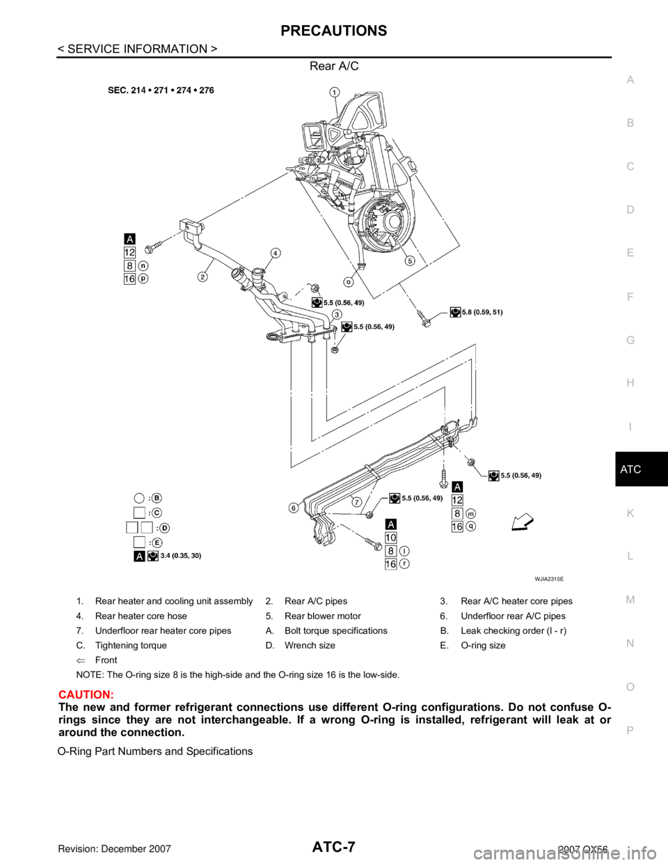
Rear A/C
CAUTION:
The new and former refrigerant connections use diffe rent O-ring configurations. Do not confuse O-
rings since they are not interchangeable. If a wrong O-ring is installed, refrigerant will leak at or
around the connection.
O-Ring Part Numbers and Specifications
WJIA2315E
1. Rear heater and cooling unit assembly 2. Rear A/C pipes 3. Rear A/C heater core pipes
4. Rear heater core hose 5. Rear blower motor 6. Underfloor rear A/C pipes
7. Underfloor rear heater core pipes A. Bolt torque specifications B. Leak checking order (l - r)
C. Tightening torque D. Wrench size E. O-ring size
⇐ Front
NOTE: The O-ring size 8 is the high-side and the O-ring size 16 is the low-side.