change key battery INFINITI QX56 2007 Factory Service Manual
[x] Cancel search | Manufacturer: INFINITI, Model Year: 2007, Model line: QX56, Model: INFINITI QX56 2007Pages: 3061, PDF Size: 64.56 MB
Page 693 of 3061
BCS-6
< SERVICE INFORMATION >
BCM (BODY CONTROL MODULE)
• When CAN communication operation is detected, it switches to CAN communication status.
• When a state of the following switches changes, it switches to CAN communication state:
- Ignition switch
- Key switch (insert)
- Hazard switch
- Main door lock/unlock switch
- Front door switch (LH, RH)
- Rear door switch (LH, RH)
- Back latch (door ajar switch)
- Glass hatch ajar switch
- Combination switch (passing, lighting switch 1st position, front fog lamp)
- Keyfob (lock/unlock signal)
- Front door lock assembly LH (key cylinder switch)
• When control performed only by BCM is required by switch, it shifts to CAN communication inactive
mode.
• Status of combination switch reading function is changed.
SYSTEMS CONTROLLED BY BCM DIRECTLY
• Power door lock system. Refer to BL-15.
• Remote keyless entry system. Refer to BL-37
.
• Power window system. Refer to GW-15
. NOTE
• Sunroof system. Refer to RF-10. NOTE
• Room lamp timer. Refer to LT-101.
• Warning chime system. Refer to DI-36
.
• Turn signal and hazard warning lamps system. Refer to LT- 5 7
.
• Trailer turn signal and hazard warning lamps system (if equipped). Refer to LT- 9 4
.
• Rear wiper and washer system. Refer to WW-26
.
NOTE:
Power supply only. No system control.
SYSTEMS CONTROLLED BY BCM AND IPDM E/R
• Panic system. Refer to BL-37.
• Vehicle security system. Refer to BL-60
.
• IVIS (NATS) system. Refer to BL-116
.
• Headlamp, tail lamp, front fog lamp, auto light and battery saver control systems. Refer to LT- 5
, LT- 2 4, LT- 8 2,
LT- 4 9
or LT- 3 4.
• Front wiper and washer system. Refer to WW-3
.
• Rear window defogger system. Refer to GW-68
.
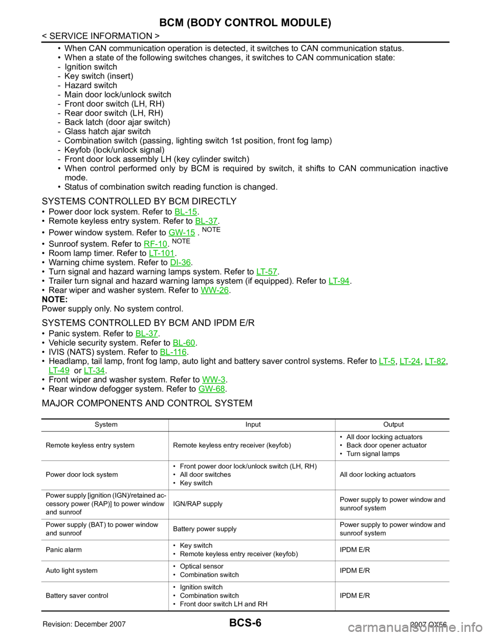
MAJOR COMPONENTS AND CONTROL SYSTEM
System Input Output
Remote keyless entry system Remote keyless entry receiver (keyfob)• All door locking actuators
• Back door opener actuator
• Turn signal lamps
Power door lock system• Front power door lock/unlock switch (LH, RH)
• All door switches
• Key switchAll door locking actuators
Power supply [ignition (IGN)/retained ac-
cessory power (RAP)] to power window
and sunroofIGN/RAP supplyPower supply to power window and
sunroof system
Power supply (BAT) to power window
and sunroofBattery power supplyPower supply to power window and
sunroof system
Panic alarm• Key switch
• Remote keyless entry receiver (keyfob)IPDM E/R
Auto light system• Optical sensor
• Combination switchIPDM E/R
Battery saver control• Ignition switch
• Combination switch
• Front door switch LH and RHIPDM E/R
Page 759 of 3061
BL-48
< SERVICE INFORMATION >
REMOTE KEYLESS ENTRY SYSTEM
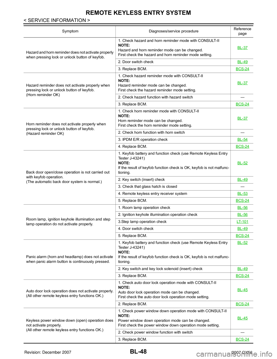
Hazard and horn reminder does not activate properly
when pressing lock or unlock button of keyfob.1. Check hazard and horn reminder mode with CONSULT-II
NOTE:
Hazard and horn reminder mode can be changed.
First check the hazard and horn reminder mode setting.BL-37
2. Door switch checkBL-49
3. Replace BCM.BCS-24
Hazard reminder does not activate properly when
pressing lock or unlock button of keyfob.
(Horn reminder OK)1. Check hazard reminder mode with CONSULT-II
NOTE:
Hazard reminder mode can be changed.
First check the hazard reminder mode setting.BL-37
2. Check hazard function with hazard switch —
3. Replace BCM.BCS-24
Horn reminder does not activate properly when
pressing lock or unlock button of keyfob.
(Hazard reminder OK)1. Check horn reminder mode with CONSULT-II
NOTE:
Horn reminder mode can be changed.
First check the horn reminder mode setting.BL-37
2. Check horn function with horn switch —
3. IPDM E/R operation checkBL-54
4. Replace BCM.BCS-24
Back door open/close operation is not carried out
with keyfob operation.
(The automatic back door system is normal.)1. Keyfob battery and function check (use Remote Keyless Entry
Tester J-43241)
NOTE:
If the result of keyfob function check is OK, keyfob is not malfunc-
tioning.BL-52
2. Key switch (insert) checkBL-49
3. Check that glass hatch is closed —
4. Remote keyless entry receiver systemBL-53
5. Replace BCM.BCS-24
Room lamp, ignition keyhole illumination and step
lamp operation do not activate properly.1. Room lamp operation checkBL-56
2. Ignition keyhole illumination operation checkBL-56
3.Step lamp operation checkLT- 1 0 1
4. Door switch checkBL-49
5. Replace BCM.BCS-24
Panic alarm (horn and headlamp) does not activate
when panic alarm button is continuously pressed.1. Keyfob battery and function check (use Remote Keyless Entry
Tester J-43241)
NOTE:
If the result of keyfob function check is OK, keyfob is not malfunc-
tioning.BL-52
2. Key switch and key lock solenoid (insert) checkBL-49
3. Replace BCM.BCS-24
Auto door lock operation does not activate properly.
(All other remote keyless entry functions OK.)1. Check auto door lock operation mode with CONSULT-II
NOTE:
Auto door lock operation mode can be changed.
First check the auto door lock operation mode setting.BL-45
2. Replace BCM.BCS-24
Keyless power window down (open) operation does
not activate properly.
(All other remote keyless entry functions OK.)1. Check power window down operation mode with CONSULT-II
NOTE:
Power window down operation mode can be changed.
First check the power window down operation mode setting.BL-45
2. Check power window function with switch —
3. Replace BCM.BCS-24
Symptom Diagnoses/service procedureReference
page
Page 1054 of 3061
WARNING CHIME
DI-43
< SERVICE INFORMATION >
C
D
E
F
G
H
I
J
L
MA
B
DI
N
O
P
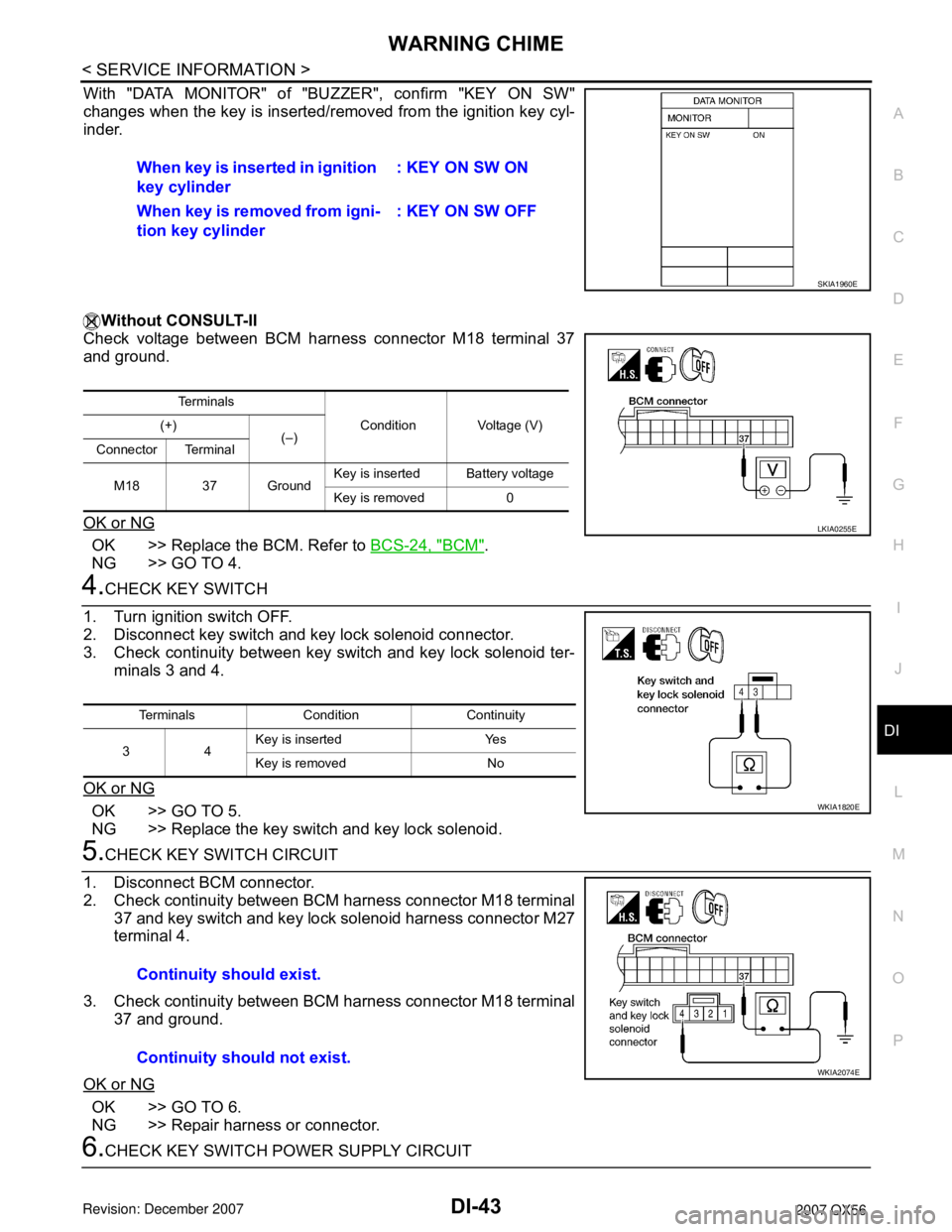
With "DATA MONITOR" of "BUZZER", confirm "KEY ON SW"
changes when the key is inserted/removed from the ignition key cyl-
inder.
Without CONSULT-II
Check voltage between BCM harness connector M18 terminal 37
and ground.
OK or NG
OK >> Replace the BCM. Refer to BCS-24, "BCM".
NG >> GO TO 4.
4.CHECK KEY SWITCH
1. Turn ignition switch OFF.
2. Disconnect key switch and key lock solenoid connector.
3. Check continuity between key switch and key lock solenoid ter-
minals 3 and 4.
OK or NG
OK >> GO TO 5.
NG >> Replace the key switch and key lock solenoid.
5.CHECK KEY SWITCH CIRCUIT
1. Disconnect BCM connector.
2. Check continuity between BCM harness connector M18 terminal
37 and key switch and key lock solenoid harness connector M27
terminal 4.
3. Check continuity between BCM harness connector M18 terminal
37 and ground.
OK or NG
OK >> GO TO 6.
NG >> Repair harness or connector.
6.CHECK KEY SWITCH POWER SUPPLY CIRCUITWhen key is inserted in ignition
key cylinder: KEY ON SW ON
When key is removed from igni-
tion key cylinder: KEY ON SW OFF
SKIA1960E
Te r m i n a l s
Condition Voltage (V) (+)
(–)
Connector Terminal
M18 37 GroundKey is insertedBattery voltage
Key is removed 0
LKIA0255E
Terminals Condition Continuity
34Key is inserted Yes
Key is removed No
WKIA1820E
Continuity should exist.
Continuity should not exist.
WKIA2074E
Page 1055 of 3061
DI-44
< SERVICE INFORMATION >
WARNING CHIME
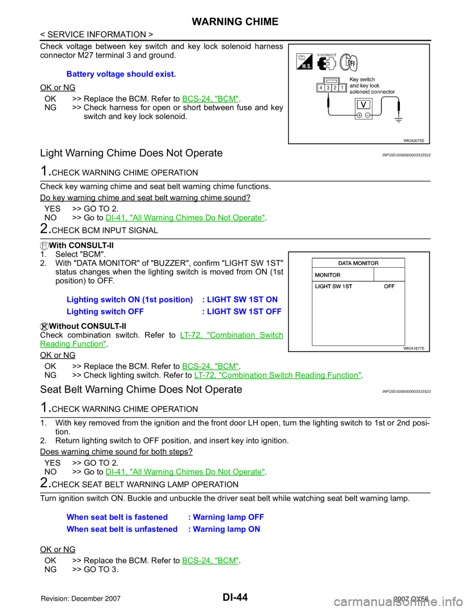
Check voltage between key switch and key lock solenoid harness
connector M27 terminal 3 and ground.
OK or NG
OK >> Replace the BCM. Refer to BCS-24, "BCM".
NG >> Check harness for open or short between fuse and key
switch and key lock solenoid.
Light Warning Chime Does Not OperateINFOID:0000000003533522
1.CHECK WARNING CHIME OPERATION
Check key warning chime and seat belt warning chime functions.
Do key warning chime and seat belt warning chime sound?
YES >> GO TO 2.
NO >> Go to DI-41, "
All Warning Chimes Do Not Operate".
2.CHECK BCM INPUT SIGNAL
With CONSULT-II
1. Select "BCM".
2. With "DATA MONITOR" of "BUZZER", confirm "LIGHT SW 1ST"
status changes when the lighting switch is moved from ON (1st
position) to OFF.
Without CONSULT-II
Check combination switch. Refer to LT-72, "
Combination Switch
Reading Function".
OK or NG
OK >> Replace the BCM. Refer to BCS-24, "BCM".
NG >> Check lighting switch. Refer to LT-72, "
Combination Switch Reading Function".
Seat Belt Warning Chime Does Not OperateINFOID:0000000003533523
1.CHECK WARNING CHIME OPERATION
1. With key removed from the ignition and the front door LH open, turn the lighting switch to 1st or 2nd posi-
tion.
2. Return lighting switch to OFF position, and insert key into ignition.
Does warning chime sound for both steps?
YES >> GO TO 2.
NO >> Go to DI-41, "
All Warning Chimes Do Not Operate".
2.CHECK SEAT BELT WARNING LAMP OPERATION
Turn ignition switch ON. Buckle and unbuckle the driver seat belt while watching seat belt warning lamp.
OK or NG
OK >> Replace the BCM. Refer to BCS-24, "BCM".
NG >> GO TO 3.Battery voltage should exist.
WKIA2075E
Lighting switch ON (1st position) : LIGHT SW 1ST ON
Lighting switch OFF : LIGHT SW 1ST OFF
WKIA1877E
When seat belt is fastened : Warning lamp OFF
When seat belt is unfastened : Warning lamp ON
Page 1995 of 3061
SERVICE INFORMATION FOR ELECTRICAL INCIDENT
GI-29
< SERVICE INFORMATION >
C
D
E
F
G
H
I
J
K
L
MB
GI
N
O
P
• Close the relay and probe at the solenoid.
voltage; open is further down the circuit than the solenoid.
no voltage; open is between relay and solenoid (point C).
Any powered circuit can be diagnosed using the approach in the previous example.
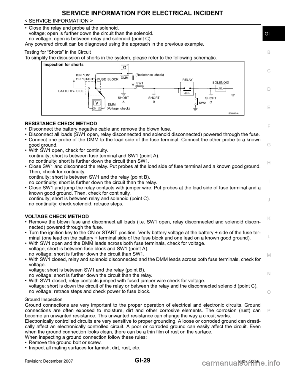
Testing for “Shorts” in the Circuit
To simplify the discussion of shorts in the system, please refer to the following schematic.
RESISTANCE CHECK METHOD
• Disconnect the battery negative cable and remove the blown fuse.
• Disconnect all loads (SW1 open, relay disconnected and solenoid disconnected) powered through the fuse.
• Connect one probe of the DMM to the load side of the fuse terminal. Connect the other probe to a known
good ground.
• With SW1 open, check for continuity.
continuity; short is between fuse terminal and SW1 (point A).
no continuity; short is further down the circuit than SW1.
• Close SW1 and disconnect the relay. Put probes at the load side of fuse terminal and a known good ground.
Then, check for continuity.
continuity; short is between SW1 and the relay (point B).
no continuity; short is further down the circuit than the relay.
• Close SW1 and jump the relay contacts with jumper wire. Put probes at the load side of fuse terminal and a
known good ground. Then, check for continuity.
continuity; short is between relay and solenoid (point C).
no continuity; check solenoid, retrace steps.
VOLTAGE CHECK METHOD
• Remove the blown fuse and disconnect all loads (i.e. SW1 open, relay disconnected and solenoid discon-
nected) powered through the fuse.
• Turn the ignition key to the ON or START position. Verify battery voltage at the battery + side of the fuse ter-
minal (one lead on the battery + terminal side of the fuse block and one lead on a known good ground).
• With SW1 open and the DMM leads across both fuse terminals, check for voltage.
voltage; short is between fuse block and SW1 (point A).
no voltage; short is further down the circuit than SW1.
• With SW1 closed, relay and solenoid disconnected and the DMM leads across both fuse terminals, check for
voltage.
voltage; short is between SW1 and the relay (point B).
no voltage; short is further down the circuit than the relay.
• With SW1 closed, relay contacts jumped with fused jumper wire check for voltage.
voltage; short is down the circuit of the relay or between the relay and the disconnected solenoid (point C).
no voltage; retrace steps and check power to fuse block.
Ground Inspection
Ground connections are very important to the proper operation of electrical and electronic circuits. Ground
connections are often exposed to moisture, dirt and other corrosive elements. The corrosion (rust) can
become an unwanted resistance. This unwanted resistance can change the way a circuit works.
Electronically controlled circuits are very sensitive to proper grounding. A loose or corroded ground can drasti-
cally affect an electronically controlled circuit. A poor or corroded ground can easily affect the circuit. Even
when the ground connection looks clean, there can be a thin film of rust on the surface.
When inspecting a ground connection follow these rules:
• Remove the ground bolt or screw.
• Inspect all mating surfaces for tarnish, dirt, rust, etc.
SGI847-A
Page 2310 of 3061

INTERIOR ROOM LAMP
LT-103
< SERVICE INFORMATION >
C
D
E
F
G
H
I
J
L
MA
B
LT
N
O
P
• through grounds M57, M61 and M79.
When a signal, or combination of signals is received by BCM, ground is supplied
• through BCM terminal 63
• to door mirror LH and RH terminal 13
• to front room/map lamp assembly terminal 1
• through front room/map lamp assembly terminal 2
• to personal lamps terminal 1, and
• through BCM terminal 49
• to cargo lamp terminal 1.
With power and ground supplied, the lamps illuminate.
SWITCH OPERATION
When any door switch is ON (door is opened), ground is supplied
• to front and rear step lamps LH and RH and foot lamp LH and RH terminal –
• through BCM terminal 62.
And power is supplied
• through BCM terminal 56
• to front and rear step lamps LH and RH terminal +
• to ignition keyhole illumination terminal +
• to door mirror LH and RH terminal 12
• to front room/map lamp assembly terminal 6
• to vanity lamp LH and RH terminal 1
• to personal lamp 2nd row and 3rd row terminal 3
• to cargo lamp terminal 2, and
• to foot lamp LH and RH terminal +.
When map lamp switch is ON, ground is supplied
• to front room/map lamp assembly terminal 5
• through grounds M57, M61 and M79.
When vanity lamp (LH and RH) is ON, ground is supplied
• to vanity lamp (LH and RH) terminal 2
• through grounds M57, M61 and M79.
When cargo lamp is ON, ground is supplied through cargo lamp case ground.
ROOM LAMP TIMER OPERATION
When lamp switch is in DOOR position and all conditions below are met, BCM performs timer control (maxi-
mum 30 seconds) for interior room lamp and map lamp ON/OFF.
Power is supplied
• through 10A fuse [No. 19, located in the fuse block (J/B)]
• to key switch and key lock solenoid terminal 3.
Key is removed from ignition key cylinder (key switch OFF), power will not be supplied to BCM terminal 37.
Serial data is supplied
• to BCM terminal 22
• through main power window and door lock/unlock switch terminal 14.
At the time that front door LH is opened, BCM detects that front door LH is unlocked. It determines that interior
room lamp and map lamp timer operation conditions are met, and turns the interior room lamps ON for 30 sec-
onds.
Key is in ignition key cylinder (key switch ON), power is supplied
• through key switch and key lock solenoid terminal 4
• to BCM terminal 37.
When key is removed from key switch and key lock solenoid (key switch OFF), power supply to BCM terminal
37 is terminated. BCM detects that key has been removed, determines that interior room lamp and map lamp
timer conditions are met, and turns the interior room lamps ON for 30 seconds.
When front door LH opens → closes, and the key is not inserted in the key switch and key lock solenoid (key
switch OFF), BCM terminal 47 changes between 0V (door open) → 12V (door closed). The BCM determines
that conditions for interior room lamp operation are met and turns the interior room lamp ON for 30 seconds.
Timer control is canceled under the following conditions.
• Front door LH is locked [when locked by keyfob, main power window and door lock/unlock switch, or front
door lock assembly LH (key cylinder switch)]
• Front door LH is opened (front door switch LH turns ON)
• Ignition switch ON.
INTERIOR LAMP BATTERY SAVER CONTROL
Page 2311 of 3061

LT-104
< SERVICE INFORMATION >
INTERIOR ROOM LAMP
If interior lamp is left “ON”, it will not be turned off even when door is closed.
BCM turns off interior lamp automatically to save battery 30 minutes after ignition switch is turned off.
BCM controls interior lamps listed below:
• Vanity lamp
• Room/map lamp
• Cargo lamp
• Personal lamp
• Step lamps
• Puddle lamps
• Foot lamps
• Ignition keyhole illumination
After lamps turn OFF by the battery saver system, the lamps illuminate again when
• signal received from keyfob, or main power window and door lock/unlock switch or front door lock assembly
LH (key cylinder switch) is locked or unlocked
• door is opened or closed
• key is removed from ignition key cylinder (key switch OFF) or inserted in ignition key cylinder (key switch
ON).
Interior lamp battery saver control period can be changed by the function setting of CONSULT-II.