driver seat adjustment INFINITI QX56 2007 Factory Service Manual
[x] Cancel search | Manufacturer: INFINITI, Model Year: 2007, Model line: QX56, Model: INFINITI QX56 2007Pages: 3061, PDF Size: 64.56 MB
Page 714 of 3061

PRECAUTIONS
BL-3
< SERVICE INFORMATION >
C
D
E
F
G
H
J
K
L
MA
B
BL
N
O
P
SERVICE INFORMATION
PRECAUTIONS
Precaution for Supplemental Restraint System (SRS) "AIR BAG" and "SEAT BELT
PRE-TENSIONER"
INFOID:0000000003532884
The Supplemental Restraint System such as “AIR BAG” and “SEAT BELT PRE-TENSIONER”, used along
with a front seat belt, helps to reduce the risk or severity of injury to the driver and front passenger for certain
types of collision. This system includes seat belt switch inputs and dual stage front air bag modules. The SRS
system uses the seat belt switches to determine the front air bag deployment, and may only deploy one front
air bag, depending on the severity of a collision and whether the front occupants are belted or unbelted.
Information necessary to service the system safely is included in the SRS and SB section of this Service Man-
ual.
WARNING:
• To avoid rendering the SRS inoperative, which could increase the risk of personal injury or death in
the event of a collision which would result in air bag inflation, all maintenance must be performed by
an authorized NISSAN/INFINITI dealer.
• Improper maintenance, including incorrect removal and installation of the SRS, can lead to personal
injury caused by unintentional activation of the system. For removal of Spiral Cable and Air Bag
Module, see the SRS section.
• Do not use electrical test equipment on any circuit related to the SRS unless instructed to in this
Service Manual. SRS wiring harnesses can be identified by yellow and/or orange harnesses or har-
ness connectors.
Precaution for workINFOID:0000000003532885
• After removing and installing the opening/closing parts, be sure to carry out fitting adjustments to check their
operation.
• Check the lubrication level, damage, and wear of each part. If necessary, grease or replace it.
Page 1051 of 3061

DI-40
< SERVICE INFORMATION >
WARNING CHIME
How to Proceed with Trouble Diagnosis
INFOID:0000000003533516
1. Confirm the symptom or customer complaint.
2. Understand operation description and function description. Refer to DI-36, "
System Description".
3. Perform the preliminary check. Refer to DI-40, "
Preliminary Check".
4. Check symptom and repair or replace the cause of malfunction.
5. Does the warning chime operate properly? If so, go to 6. If not, go to 3.
6. Inspection End.
Preliminary CheckINFOID:0000000003533517
INSPECTION FOR POWER SUPPLY AND GROUND CIRCUIT
Refer to BCS-15, "BCM Power Supply and Ground Circuit Inspection".
CONSULT-II Function (BCM)INFOID:0000000003533518
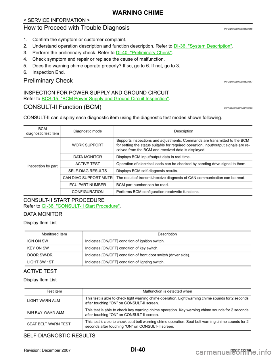
CONSULT-II can display each diagnostic item using the diagnostic test modes shown following.
CONSULT-II START PROCEDURE
Refer to GI-36, "CONSULT-II Start Procedure".
DATA MONITOR
Display Item List
ACTIVE TEST
Display Item List
SELF-DIAGNOSTIC RESULTS
BCM
diagnostic test itemDiagnostic mode Description
Inspection by partWORK SUPPORTSupports inspections and adjustments. Commands are transmitted to the BCM
for setting the status suitable for required operation, input/output signals are re-
ceived from the BCM and received data is displayed.
DATA MONITOR Displays BCM input/output data in real time.
ACTIVE TEST Operation of electrical loads can be checked by sending drive signal to them.
SELF-DIAG RESULTS Displays BCM self-diagnosis results.
CAN DIAG SUPPORT MNTR The result of transmit/receive diagnosis of CAN communication can be read.
ECU PART NUMBER BCM part number can be read.
CONFIGURATION Performs BCM configuration read/write functions.
Monitored item Description
IGN ON SW Indicates [ON/OFF] condition of ignition switch.
KEY ON SW Indicates [ON/OFF] condition of key switch.
DOOR SW-DR Indicates [ON/OFF] condition of front door switch (driver side).
LIGHT SW 1ST Indicates [ON/OFF] condition of lighting switch.
Test item Malfunction is detected when
LIGHT WARN ALMThis test is able to check light warning chime operation. Light warning chime sounds for 2 seconds
after touching “ON” on CONSULT-II screen.
IGN KEY WARN ALMThis test is able to check key warning chime operation. Key warning chime sounds for 2 seconds
after touching “ON” on CONSULT-II screen.
SEAT BELT WARN TESTThis test is able to check seat belt warning chime operation. Seat belt warning chime sounds for 2
seconds after touching “ON” on CONSULT-II screen.
Page 2262 of 3061

FRONT FOG LAMP
LT-55
< SERVICE INFORMATION >
C
D
E
F
G
H
I
J
L
MA
B
LT
N
O
P
Aiming AdjustmentINFOID:0000000003533400
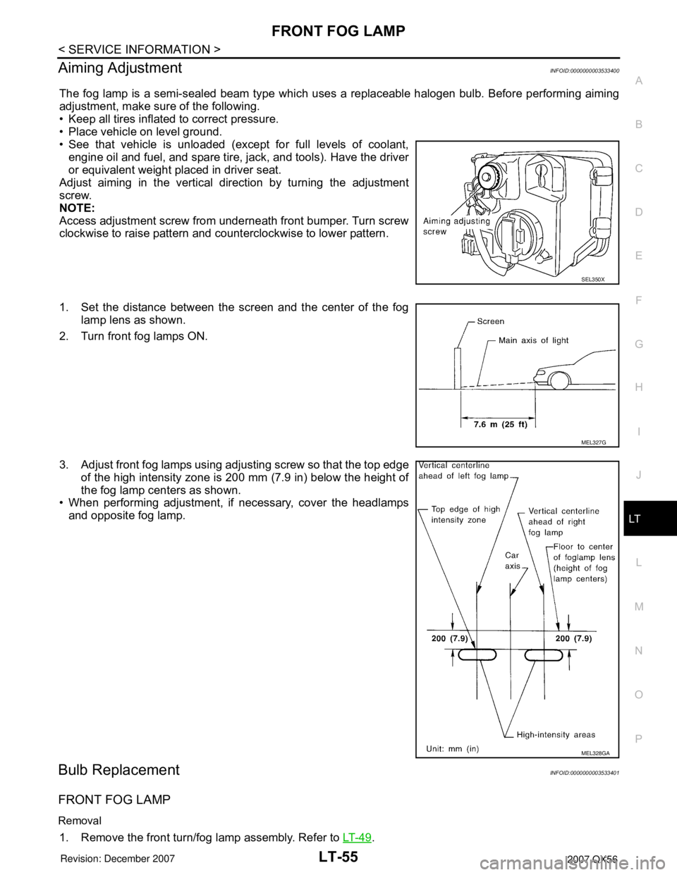
The fog lamp is a semi-sealed beam type which uses a replaceable halogen bulb. Before performing aiming
adjustment, make sure of the following.
• Keep all tires inflated to correct pressure.
• Place vehicle on level ground.
• See that vehicle is unloaded (except for full levels of coolant,
engine oil and fuel, and spare tire, jack, and tools). Have the driver
or equivalent weight placed in driver seat.
Adjust aiming in the vertical direction by turning the adjustment
screw.
NOTE:
Access adjustment screw from underneath front bumper. Turn screw
clockwise to raise pattern and counterclockwise to lower pattern.
1. Set the distance between the screen and the center of the fog
lamp lens as shown.
2. Turn front fog lamps ON.
3. Adjust front fog lamps using adjusting screw so that the top edge
of the high intensity zone is 200 mm (7.9 in) below the height of
the fog lamp centers as shown.
• When performing adjustment, if necessary, cover the headlamps
and opposite fog lamp.
Bulb ReplacementINFOID:0000000003533401
FRONT FOG LAMP
Removal
1. Remove the front turn/fog lamp assembly. Refer to LT- 4 9.
SEL350X
MEL327G
MEL328GA
Page 2704 of 3061

SE-32
< SERVICE INFORMATION >
AUTOMATIC DRIVE POSITIONER
1. Turn ignition switch OFF.
2. Check continuity between the driver seat control unit connector
P2 terminal 32, P3 terminal 48 and ground.
OK or NG
OK >> Driver seat control unit circuit check is OK. Check the
automatic drive positioner control unit. GO TO 4.
NG >> Repair or replace harness.
4.CHECK AUTOMATIC DRIVE POSITIONER CONTROL UNIT POWER SUPPLY CIRCUIT
1. Disconnect automatic drive positioner control unit.
2. Check voltage between automatic drive positioner control unit
connector M34 terminals 34, 39 and ground.
OK or NG
OK >> GO TO 5.
NG >> Repair or replace harness.
5.CHECK AUTOMATIC DRIVE POSITIONER CONTROL UNIT GROUND CIRCUIT
Check continuity between the automatic drive positioner control unit
connector M34 terminals 40, 48 and ground.
OK or NG
OK >> Automatic drive positioner control unit circuit is OK.
NG >> Repair or replace harness.
CONSULT-II Function (AUTO DRIVE POS.)INFOID:0000000003533170
CONSULT-II can display each diagnostic item using the diagnostic test modes shown following. 32 - Ground : Continuity should exist.
48 - Ground : Continuity should exist.
PIIA4542E
ConnectorTe r m i n a l s
Power
sourceConditionVoltage (V)
(Approx.)
(+) (-)
M3434 GroundBattery
power
supplyIgnition
switch
OFFBattery
voltage
39 GroundBattery
power
supplyIgnition
switch
OFFBattery
voltage
PIIA4543E
40 - Ground : Continuity should exist.
48 - Ground : Continuity should exist.
PIIA4544E
AUTO DRIVE POS.
diagnostic modeDescription
WORK SUPPORTSupports inspections and adjustments. Commands are transmitted to the driver seat
control unit for setting the status suitable for required operation, input/output signals
are received from the driver seat control unit and received data is displayed.
SELF-DIAG RESULTS Displays driver seat control unit self-diagnosis results.
DATA MONITOR Displays driver seat control unit input/output data in real time.
CAN DIAG SUPPORT MNTR The result of transmit/receive diagnosis of CAN communication can be read.
ACTIVE TEST Operation of electrical loads can be checked by sending drive signal to them.
ECU PART NUMBER Driver seat control unit part number can be read.
Page 2825 of 3061

PRECAUTIONS
TF-3
< SERVICE INFORMATION >
C
E
F
G
H
I
J
K
L
MA
B
TF
N
O
P
SERVICE INFORMATION
PRECAUTIONS
Precaution for Supplemental Restraint System (SRS) "AIR BAG" and "SEAT BELT
PRE-TENSIONER"
INFOID:0000000003532506
The Supplemental Restraint System such as “AIR BAG” and “SEAT BELT PRE-TENSIONER”, used along
with a front seat belt, helps to reduce the risk or severity of injury to the driver and front passenger for certain
types of collision. This system includes seat belt switch inputs and dual stage front air bag modules. The SRS
system uses the seat belt switches to determine the front air bag deployment, and may only deploy one front
air bag, depending on the severity of a collision and whether the front occupants are belted or unbelted.
Information necessary to service the system safely is included in the SRS and SB section of this Service Man-
ual.
WARNING:
• To avoid rendering the SRS inoperative, which could increase the risk of personal injury or death in
the event of a collision which would result in air bag inflation, all maintenance must be performed by
an authorized NISSAN/INFINITI dealer.
• Improper maintenance, including incorrect removal and installation of the SRS, can lead to personal
injury caused by unintentional activation of the system. For removal of Spiral Cable and Air Bag
Module, see the SRS section.
• Do not use electrical test equipment on any circuit related to the SRS unless instructed to in this
Service Manual. SRS wiring harnesses can be identified by yellow and/or orange harnesses or har-
ness connectors.
Precaution for Transfer Assembly and Transfer Control Unit ReplacementINFOID:0000000003532507
When replacing transfer assembly or transfer control unit, check the 4WD shift indicator lamp as follows.
1. Turn ignition switch “ON”.
2. Check 4WD shift indicator lamp is turned ON for approx. 1 second.
• If OK, the position between transfer assembly and transfer control unit is correct.
• If NG, the position is different between transfer assembly and transfer control unit.
Adjust the position between transfer assembly and transfer control unit. Refer to "METHOD FOR POSITION
ADJUSTMENT".
METHOD FOR POSITION ADJUSTMENT
1. Start engine. Run the engine for at least 10 seconds.
2. Stop vehicle and move A/T selector lever to “N” position with brake pedal depressed. Stay in "N" for at
least 2 seconds.
3. Turn 4WD shift switch to “2WD” position. Stay in "2WD" for at least 2 seconds.
4. Turn ignition switch “OFF”.
5. Start engine.
6. Erase self-diagnosis. Refer to TF-42, "
CONSULT-II Function (ALL MODE AWD/4WD)" (with CONSULT-II)
or TF-48, "
Self-Diagnosis Procedure" (without CONSULT-II).
7. Check 4WD shift indicator lamp. Refer to TF-31, "
Inspections Before Trouble Diagnosis".
If 4WD shift indicator lamp does not indicate "2WD", install new transfer control unit and retry the above
check.