length INFINITI QX56 2007 Factory Service Manual
[x] Cancel search | Manufacturer: INFINITI, Model Year: 2007, Model line: QX56, Model: INFINITI QX56 2007Pages: 3061, PDF Size: 64.56 MB
Page 6 of 3061

QUICK REFERENCE CHART: QX56
2007
Rear Wheel AlignmentELS00291
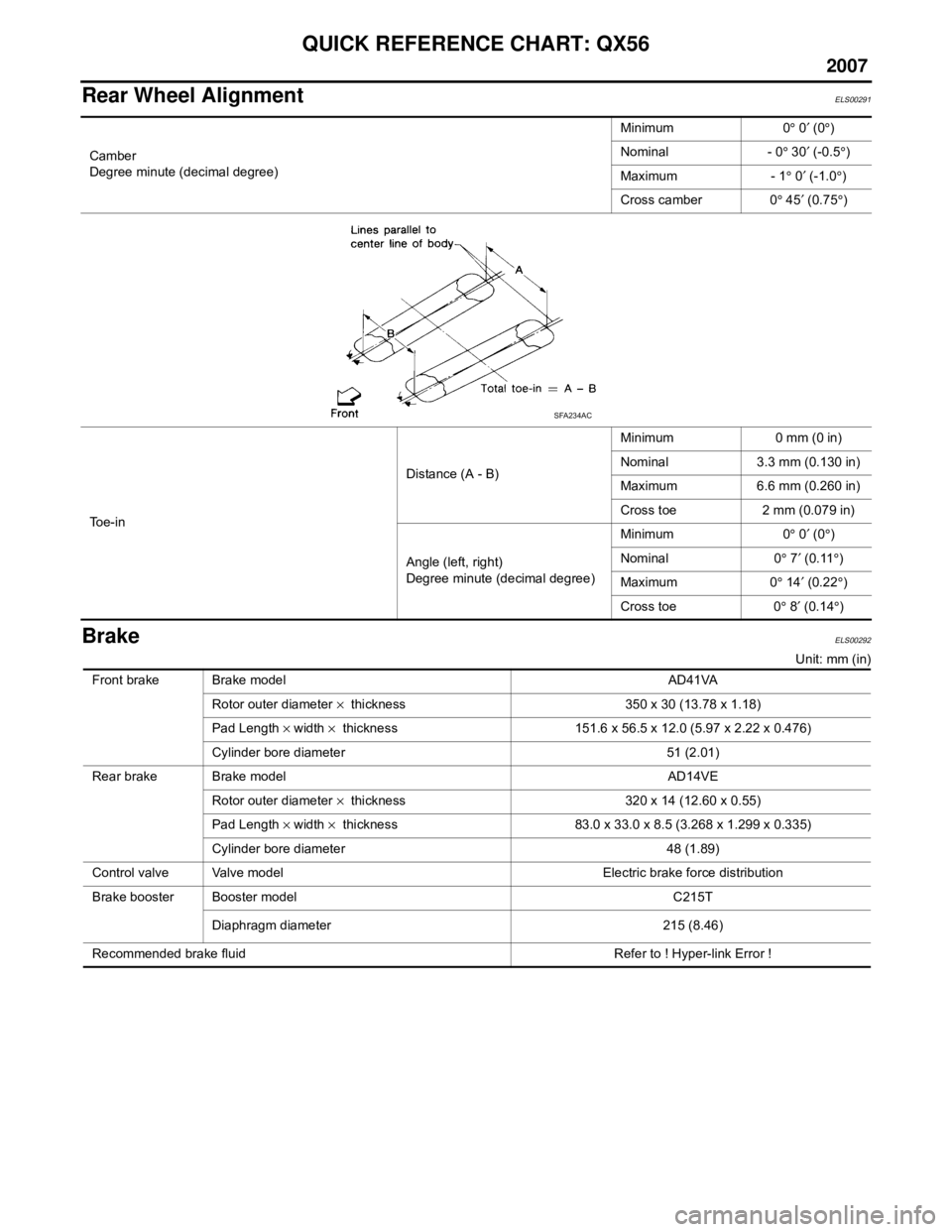
BrakeELS00292
Unit: mm (in)
Camber
Degree minute (decimal degree)
Minimum 0
° 0 ′ (0 °)
Nominal - 0 ° 30 ′ (-0.5 °)
Maximum - 1 ° 0 ′ (-1.0 °)
Cross camber 0 ° 45 ′ (0.75 °)
To e - i n Distance (A - B)
Minimum 0 mm (0 in)
Nominal 3.3 mm (0.130 in)
Maximum 6.6 mm (0.260 in)
Cross toe 2 mm (0.079 in)
Angle (left, right)
Degree minute (decimal degree) Minimum 0
° 0 ′ (0 °)
Nominal 0 ° 7 ′ (0.11 °)
Maximum 0 ° 14 ′ (0.22 °)
Cross toe 0 ° 8 ′ (0.14 °)
SFA234AC
Front brake Brake model AD41VA
Rotor outer diameter × thickness 350 x 30 (13.78 x 1.18)
Pad Length × width × thickness 151.6 x 56.5 x 12.0 (5.97 x 2.22 x 0.476)
Cylinder bore diameter 51 (2.01)
Rear brake Brake model AD14VE Rotor outer diameter × thickness 320 x 14 (12.60 x 0.55)
Pad Length × width × thickness 83.0 x 33.0 x 8.5 (3.268 x 1.299 x 0.335)
Cylinder bore diameter 48 (1.89)
Control valve Valve model Electric brake force distribution
Brake booster Booster model C215T
Diaphragm diameter 215 (8.46)
Recommended brake fluid Refer to ! Hyper-link Error !
Page 283 of 3061

ON-VEHICLE SERVICE
AT-213
< SERVICE INFORMATION >
D
E
F
G
H
I
J
K
L
MA
B
AT
N
O
P
11. Remove bolts (A), (B) and (C) from control valve with TCM.
• : Front
12. Remove control valve with TCM from transmission case.
CAUTION:
Be careful with the manual valve notch and manual plate
height. Remove it vertically.
13. Remove A/T fluid temperature sensor 2 with bracket from con-
trol valve with TCM.
14. Remove bracket from A/T fluid temperature sensor 2.
15. Remove O-ring from A/T assembly harness connector.
Bolt symbol Length mm (in) Number of bolts
A 42 (1.65) 5
B 55 (2.17) 6
C 40 (1.57) 1
SCIA8074E
SCIA5142E
SCIA5253E
SCIA5264E
SCIA5155E
Page 286 of 3061

AT-216
< SERVICE INFORMATION >
ON-VEHICLE SERVICE
7. Install control valve with TCM in transmission case.
CAUTION:
• Make sure that turbine revolution sensor securely installs
turbine revolution sensor hole.
• Hang down revolution sensor harness toward outside so
as not to disturb installation of control valve with TCM.
• Adjust A/T assembly harness connector of control valve
with TCM to terminal hole of transmission case.
• Assemble it so that manual valve cutout is engaged with
manual plate projection.
8. Install bolts (A), (B) and (C) in control valve with TCM.
• : Front
9. Tighten bolt (1), (2) and (3) temporarily to prevent dislocation. Then tighten them in order (1 → 2 → 3),
and then tighten other bolts.
• : Front
10. Tighten control valve with TCM bolts to the specified torque.
Refer to AT-228, "
Component".
SCIA5034E
SCIA5142E
Bolt symbol Length mm (in) Number of bolts
A 42 (1.65) 5
B 55 (2.17) 6
C 40 (1.57) 1
SCIA8074E
SCIA8075E
Page 316 of 3061

AT-246
< SERVICE INFORMATION >
DISASSEMBLY
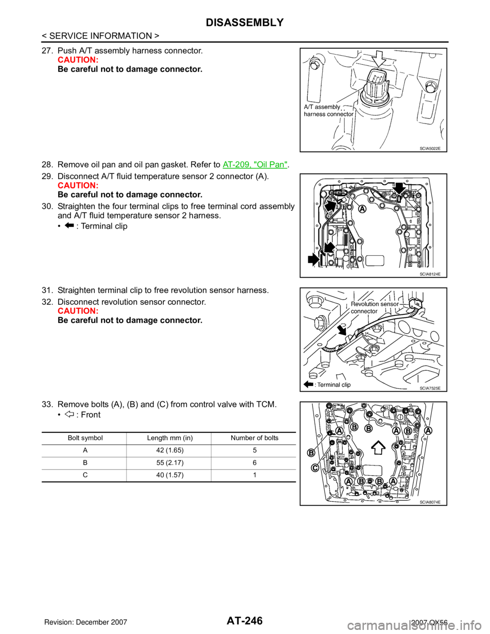
27. Push A/T assembly harness connector.
CAUTION:
Be careful not to damage connector.
28. Remove oil pan and oil pan gasket. Refer to AT-209, "
Oil Pan".
29. Disconnect A/T fluid temperature sensor 2 connector (A).
CAUTION:
Be careful not to damage connector.
30. Straighten the four terminal clips to free terminal cord assembly
and A/T fluid temperature sensor 2 harness.
• : Terminal clip
31. Straighten terminal clip to free revolution sensor harness.
32. Disconnect revolution sensor connector.
CAUTION:
Be careful not to damage connector.
33. Remove bolts (A), (B) and (C) from control valve with TCM.
• : Front
SCIA5022E
SCIA8124E
SCIA7525E
Bolt symbol Length mm (in) Number of bolts
A 42 (1.65) 5
B 55 (2.17) 6
C 40 (1.57) 1
SCIA8074E
Page 365 of 3061

ASSEMBLY
AT-295
< SERVICE INFORMATION >
D
E
F
G
H
I
J
K
L
MA
B
AT
N
O
P
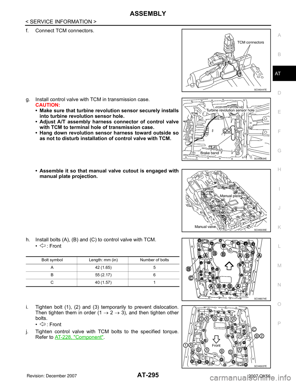
f. Connect TCM connectors.
g. Install control valve with TCM in transmission case.
CAUTION:
• Make sure that turbine revolution sensor securely installs
into turbine revolution sensor hole.
• Adjust A/T assembly harness connector of control valve
with TCM to terminal hole of transmission case.
• Hang down revolution sensor harness toward outside so
as not to disturb installation of control valve with TCM.
• Assemble it so that manual valve cutout is engaged with
manual plate projection.
h. Install bolts (A), (B) and (C) to control valve with TCM.
• : Front
i. Tighten bolt (1), (2) and (3) temporarily to prevent dislocation.
Then tighten them in order (1 → 2 → 3), and then tighten other
bolts.
• : Front
j. Tighten control valve with TCM bolts to the specified torque.
Refer to AT-228, "
Component".
SCIA5447E
SCIA5034E
SCIA5035E
Bolt symbol Length: mm (in) Number of bolts
A 42 (1.65) 5
B 55 (2.17) 6
C 40 (1.57) 1
SCIA8074E
SCIA5037E
Page 805 of 3061

BL-94
< SERVICE INFORMATION >
AUTOMATIC BACK DOOR SYSTEM
10. After approximately 5 seconds, the back door warning chime will sound for 1 second.
11. Release the power liftgate switch.
12. Immediately close the back door manually.
13. Press and release the power liftgate switch to activate operating check mode.
Self-diagnosis results are indicated by the back door warning chime.
Turn ignition switch OFF to end input signal check mode.
Diagnosis ChartINFOID:0000000003532965
Back door warning chime order Back door warning chime length
Start self-diagnosis1.5 seconds
OK NG
1. Operating conditions diagnosis 0.5 seconds 0.2 seconds
2. Back door encoder diagnosis 0.5 seconds 0.2 seconds
3. Back door clutch diagnosis 0.5 seconds 0.2 seconds
4. Back door motor diagnosis 0.5 seconds 0.2 seconds
5. Cinch latch motor diagnosis 0.5 seconds 0.2 seconds
Restart self-diagnosis 1.5 seconds
Item NG Result Refer to
1. Operating conditions diagnosis resultOne of the following operating conditions no
longer met: ignition switch ON, back door close
switch (CANCEL) ON, A/T selector lever in P
position—
2. Back door encoder diagnosis resultSensor diagnosis/short, pulse signal, pulse
signal directionBL-114
3. Back door clutch diagnosis result Back door clutch does not operateBL-114
4. Back door motor diagnosis resultBack door motor does not operate (no operat-
ing current)BL-114
5. Cinch latch motor diagnosis resultCinch latch motor does not operate (no operat-
ing current)BL-114
Symptom Suspect systems Refer to
Automatic operations are not executed from the back door fully
closed or fully open position.
(Auto closure operates normally.)Power liftgate switch system inspectionBL-95
Park switch —
Power window serial linkBL-92
Pinch strip system inspectionBL-100
Automatic operations are not carried out together with open/close
operations.
(Manual operations are normal.)Power liftgate switch system inspectionBL-95Back door close switch system inspectionBL-98
Auto back door power supply and ground cir-
cuit system inspection.BL-95
The auto closure function does not operate.
(Stops at the halfway position for auto closing operations.)Pinch strip system inspectionBL-100
During auto closing operations, if obstruction is detected, the door
does not operate in reverse.Back door motor assembly —
During close or cinch operations, the door does not operate in re-
verse if the back door handle is operated.Handle switch systemBL-104
Page 862 of 3061

BODY REPAIR
BL-151
< SERVICE INFORMATION >
C
D
E
F
G
H
J
K
L
MA
B
BL
N
O
P
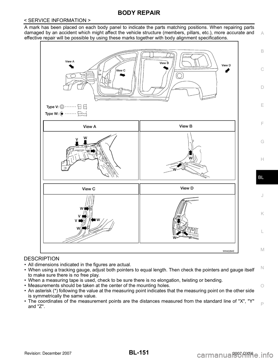
A mark has been placed on each body panel to indicate the parts matching positions. When repairing parts
damaged by an accident which might affect the vehicle structure (members, pillars, etc.), more accurate and
effective repair will be possible by using these marks together with body alignment specifications.
DESCRIPTION
• All dimensions indicated in the figures are actual.
• When using a tracking gauge, adjust both pointers to equal length. Then check the pointers and gauge itself
to make sure there is no free play.
• When a measuring tape is used, check to be sure there is no elongation, twisting or bending.
• Measurements should be taken at the center of the mounting holes.
• An asterisk (*) following the value at the measuring point indicates that the measuring point on the other side
is symmetrically the same value.
• The coordinates of the measurement points are the distances measured from the standard line of "X", "Y"
and "Z".
WIIA0284E
Page 914 of 3061

BR-16
< SERVICE INFORMATION >
BRAKE BOOSTER
• Be careful not to damage brake booster stud bolt threads. If brake booster is tilted or inclined during
installation, dash panel may damage the threads.
• Attach the check valve in the correct direction.
1. Remove engine room cover with power tool. Refer to EM-12, "
Removal and Installation" .
2. Remove engine air duct assembly. Refer to EM-15, "
Removal and Installation" .
3. Remove brake piping from brake master cylinder.
4. Remove brake master cylinder. Refer to BR-13, "
Removal and Installation" .
5. Remove vacuum hose from brake booster. Refer to BR-17
.
6. Disconnect active boost and delta stroke sensor harness connectors from brake booster assembly.
7. Remove brake pedal attachment snap pin and clevis pin from inside the vehicle.
8. Remove nuts on brake booster and brake pedal assembly.
9. Remove brake booster assembly from dash panel.
INSPECTION AFTER REMOVAL
Output Rod Length Inspection
1. Using a handy vacuum pump, apply a vacuum of – 66.7 kPa (–
500 mmHg, –19.69 inHg) to brake booster.
2. Check output rod length.
INSTALLATION
1. Loosen lock nut to adjust input rod length so that the length B (in
the figure) satisfies the specified value.
2. After adjusting “B”, temporarily tighten lock nut and install
booster assembly to the vehicle.
• Install a gaskets and spacer block between booster assembly
and the dash panel.
3. Connect brake pedal with clevis of input rod.
4. Install pedal bracket mounting nuts and tighten them to the
specified torque.
5. Install brake piping from brake master cylinder to ABS actuator. Refer to BR-10, "
Hydraulic Circuit".
6. Connect active boost and delta stroke sensor harness connectors to brake booster assembly.
7. Connect vacuum hose to brake booster.
8. Install master cylinder to booster assembly. Refer to BR-13, "
Removal and Installation" .
9. Adjust the height and play of brake pedal.
10. Tighten lock nut of input rod to specification.
11. Install engine air duct assembly. Refer to EM-15, "
Removal and Installation" .
12. Install engine room cover with power tool. Refer to EM-12, "
Removal and Installation" .
13. Refill with new brake fluid and bleed air. Refer to BR-8, "
Bleeding Brake System" .
SBR208E
Standard dimension : 15.6 − 15.9 mm (0.614 − 0.626 in)
[when vacuum is – 66.7 kPa (– 500 mmHg, – 19.69 inHg)]
Length “B” : 151 mm (5.94 in)
WFIA0382E
Page 927 of 3061

SERVICE DATA AND SPECIFICATIONS (SDS)
BR-29
< SERVICE INFORMATION >
C
D
E
G
H
I
J
K
L
MA
B
BR
N
O
P
SERVICE DATA AND SPECIFICATIONS (SDS)
General SpecificationINFOID:0000000003532748
Unit: mm (in)
Brake PedalINFOID:0000000003532749
Unit: mm (in)
Front brake Brake model AD41VA
Rotor outer diameter × thickness 350 x 30 (13.78 x 1.18)
Pad Length × width × thickness 151.6 x 56.5 x 12.0 (5.97 x 2.22 x 0.476)
Cylinder bore diameter 51 (2.01)
Rear brake Brake model AD14VE
Rotor outer diameter × thickness 320 x 14 (12.60 x 0.551)
Pad Length × width × thickness 83.0 x 33.0 x 12.13 (3.268 x 1.299 x 0.478)
Cylinder bore diameter 48 (1.89)
Control valve Valve model Electric brake force distribution
Brake booster Booster model C215T
Diaphragm diameter 215 (8.46)
Recommended brake fluid Refer to MA-10
Free height "H"182.3 - 192.3 mm (7.18 - 7.57 in)
Depressed pedal height "D" [under a force of 490 N (50 kg-f, 110 lb-f) with engine
running]More than 90.3 mm (3.55 in)
Clearance between pedal stopper and threaded end of stop lamp switch and
ASCD switch "C
1 " or “C2 ”0.74 - 1.96 mm (0.029 - 0.077 in)
Pedal play "A"3 - 11 mm (0.12 - 0.43 in)
WFIA0160E
Page 1108 of 3061

ENGINE CONTROL SYSTEM
EC-25
< SERVICE INFORMATION >
C
D
E
F
G
H
I
J
K
L
MA
EC
N
P O
*1: This sensor is not used to control the engine system. This is used only for the on board diagnosis.
*2: This signal is sent to the ECM through CAN communication line.
*3: ECM determines the start signal status by the signals of engine speed and battery voltage.
SYSTEM DESCRIPTION
The amount of fuel injected from the fuel injector is determined by the ECM. The ECM controls the length of
time the valve remains open (injection pulse duration). The amount of fuel injected is a program value in the
ECM memory. The program value is preset by engine operating conditions. These conditions are determined
by input signals (for engine speed and intake air) from both the crankshaft position sensor and the mass air
flow sensor.
VARIOUS FUEL INJECTION INCREASE/DECREASE COMPENSATION
In addition, the amount of fuel injected is compensated to improve engine performance under various operat-
ing conditions as listed below.
• When starting the engine
• During acceleration
• Hot-engine operation
• When selector lever is changed from N to D
• High-load, high-speed operation
• During deceleration
• During high engine speed operation
MIXTURE RATIO FEEDBACK CONTROL (CLOSED LOOP CONTROL)
Sensor Input signal to ECM ECM function Actuator
Crankshaft position sensor (POS)
Engine speed*
3
Piston position
Fuel injection
& mixture ratio
controlFuel injector Camshaft position sensor (PHASE)
Mass air flow sensor Amount of intake air
Engine coolant temperature sensor Engine coolant temperature
Air fuel ratio (A/F) sensor 1 Density of oxygen in exhaust gas
Throttle position sensor Throttle position
Accelerator pedal position sensor Accelerator pedal position
Park/neutral position (PNP) switch Gear position
Knock sensor Engine knocking condition
Battery
Battery voltage*
3
Power steering pressure sensor Power steering operation
Heated oxygen sensor 2*
1Density of oxygen in exhaust gas
ABS actuator and electric unit (control unit)
VDC/TCS operation command*
2
Air conditioner switch
Air conditioner operation*2
Wheel sensor
Vehicle speed*2
PBIB3020E