INFINITI QX56 2008 Factory Service Manual
QX56 2008
INFINITI
INFINITI
https://www.carmanualsonline.info/img/42/57030/w960_57030-0.png
INFINITI QX56 2008 Factory Service Manual
Page 1965 of 4083

TURN SIGNAL LAMP CIRCUITEXL-37
< COMPONENT DIAGNOSIS >
C
DE
F
G H
I
J
K
M A
B
EXL
N
O P
TURN SIGNAL LAMP CIRCUIT
DescriptionINFOID:0000000001547137
The BCM monitors inputs from the combination switch to determine when to activate the turn signals. The
BCM outputs voltage direction to the left and right turn signals during turn signal operation or both during haz-
ard warning operation. The BCM sends a turn signal i ndicator request to the combination meter via the CAN
communication lines.
The BCM performs the fast flasher operation (fail-safe) if any bulb or harness of the turn signal lamp circuit is
open.
NOTE:
Turn signal lamp blinks at normal speed when using the hazard warning lamp.
Component Function CheckINFOID:0000000001547138
1.CHECK TURN SIGNAL LAMP
CONSULT-III
1. Select "FLASHER" of BCM (F LASHER) active test item.
2. With operating the test items, chec k that the turn signal lamp blinks.
Does the turn signal lamp blink?
YES >> Turn signal lamp circuit is normal.
NO >> Refer to EXL-37, "
Diagnosis Procedure".
Diagnosis ProcedureINFOID:0000000001547139
1.CHECK TURN SIGNAL LAMP BULB
Check the applicable lamp bulb to be sure the proper bulb standard is in use and the bulb is not open.
Is the bulb OK?
YES >> GO TO 2
NO >> Replace the bulb.
2.CHECK TURN SIGNAL LA MP OUTPUT VOLTAGE
1. Turn the ignition switch OFF.
2. Disconnect the front turn/fog lamp connector or the rear combi- nation lamp connector.
3. Turn the ignition switch ON.
4. With turn signal switch operating, check the voltage between the BCM harness connector M20 and ground.
Is voltage reading as specified?
YES >> GO TO 3
NO >> Replace BCM. Refer to BCS-55, "
Removal and Installation".
LH : Turn signal lamp LH blinking
RH : Turn signal lamp RH blinking
OFF : The turn signal lamp OFF
(+)
(−)V olt a g e
Connector Terminal
M20 LH 60
Ground
RH 61
ALLIA0402ZZ
PKID0926E
Revision: March 2010 2008 QX56
Page 1966 of 4083

EXL-38
< COMPONENT DIAGNOSIS >
TURN SIGNAL LAMP CIRCUIT
3.CHECK TURN SIGNAL LAMP CIRCUIT FOR OPEN
1. Turn the ignition switch OFF.
2. Disconnect BCM connector M20.
3. Check continuity between the BCM harness connector M20 and the front turn/fog lamps.
4. Check continuity between the BCM harness connector M20 and the rear combination lamp connectors.
5. Check continuity between the BCM harness connector M20 and the door mirror connectors.
Are continuity test results as specified?
YES >> GO TO 4
NO >> Repair the harnesses or connectors.
4.CHECK TURN SIGNAL LAMP SHORT CIRCUIT
Check continuity between the BCM harness connector M20 and
ground.
Does continuity exist?
YES >> Repair the harnesses or connectors.
NO >> GO TO 5
5.CHECK TURN SIGNAL LAMP GROUND CIRCUIT
AB Continuity
Connector Terminal Connector Terminal
Front LH M2060 E101
2Yes
Front RH 61 E102
ALLIA0722GB
AB
Continuity
Connector Terminal Connector Terminal
Rear LH M2060 B35 4
Ye s
Rear RH 61 B105 4
WKIA4774E
AB
Continuity
Connector Terminal Connector Terminal
Door mirror LH M2060 D4 15
Ye s
Door mirror RH 61 D107 15
WKIA4524E
ConnectorTerminal—Continuity
LH M20 60
Ground No
RH 61
ALLIA0404GB
Revision: March 2010 2008 QX56
Page 1967 of 4083
TURN SIGNAL LAMP CIRCUITEXL-39
< COMPONENT DIAGNOSIS >
C
DE
F
G H
I
J
K
M A
B
EXL
N
O P
1. Check continuity between the front turn/fog lamp harness con- nectors and ground.
2. Check continuity between the rear combination lamp harnness connectors and ground.
3. Check continuity between the door mirrors and ground.
Are continuity test results as specified?
YES >> Replace the malfunctioning lamp.
NO >> Repair the harnesses or connectors.
Connector Terminal— Continuity
Front LH E11
3Ground Yes
Front RH E107
ALLIA0721GB
Connector Terminal— Continuity
Rear LH B35
6Ground Yes
Rear RH B105
WKIA4775E
Connector Terminal— Continuity
Door mirror RH D107 11Ground Yes
Door mirror LH D4
WKIA4525E
Revision: March 2010 2008 QX56
Page 1968 of 4083

EXL-40
< COMPONENT DIAGNOSIS >
OPTICAL SENSOR
OPTICAL SENSOR
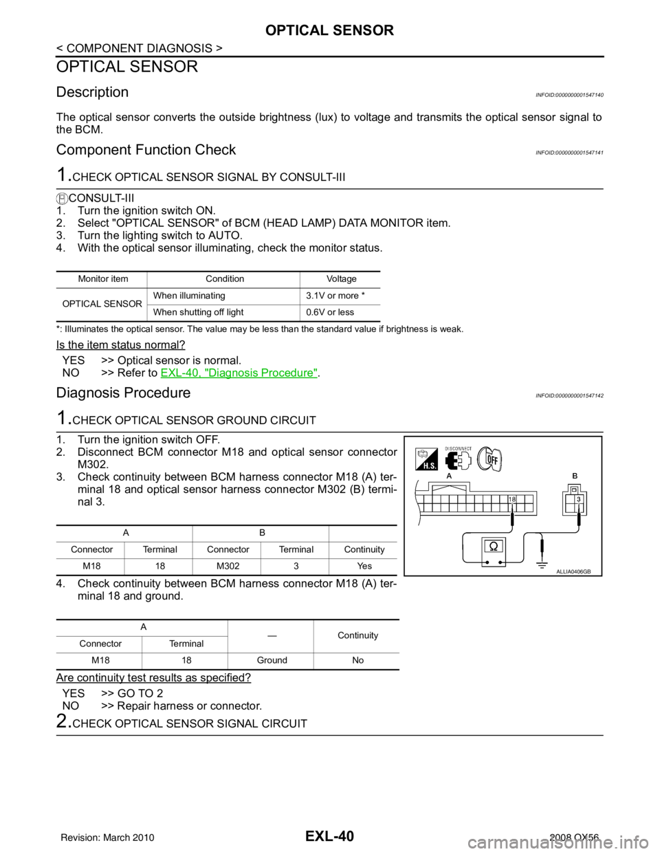
DescriptionINFOID:0000000001547140
The optical sensor converts the outside brightness (lux) to voltage and transmits the optical sensor signal to
the BCM.
Component Function CheckINFOID:0000000001547141
1.CHECK OPTICAL SENSOR SIGNAL BY CONSULT-III
CONSULT-III
1. Turn the ignition switch ON.
2. Select "OPTICAL SENSOR" of BCM (HEAD LAMP) DATA MONITOR item.
3. Turn the lighting switch to AUTO.
4. With the optical sensor illuminating, check the monitor status.
*: Illuminates the optical sensor. The value may be less than the standard value if brightness is weak.
Is the item status normal?
YES >> Optical sensor is normal.
NO >> Refer to EXL-40, "
Diagnosis Procedure".
Diagnosis ProcedureINFOID:0000000001547142
1.CHECK OPTICAL SENSOR GROUND CIRCUIT
1. Turn the ignition switch OFF.
2. Disconnect BCM connector M18 and optical sensor connector M302.
3. Check continuity between BCM harness connector M18 (A) ter-
minal 18 and optical sensor harness connector M302 (B) termi-
nal 3.
4. Check continuity between BCM harness connector M18 (A) ter- minal 18 and ground.
Are continuity test results as specified?
YES >> GO TO 2
NO >> Repair harness or connector.
2.CHECK OPTICAL SENSOR SIGNAL CIRCUIT
Monitor item ConditionVoltage
OPTICAL SENSOR When illuminating
3.1V or more *
When shutting off light 0.6V or less
AB
Connector Terminal Connector Terminal Continuity M18 18M302 3Yes
A —Continuity
Connector Terminal
M18 18Ground No
ALLIA0406GB
Revision: March 2010 2008 QX56
Page 1996 of 4083
EXL-68
< COMPONENT DIAGNOSIS >
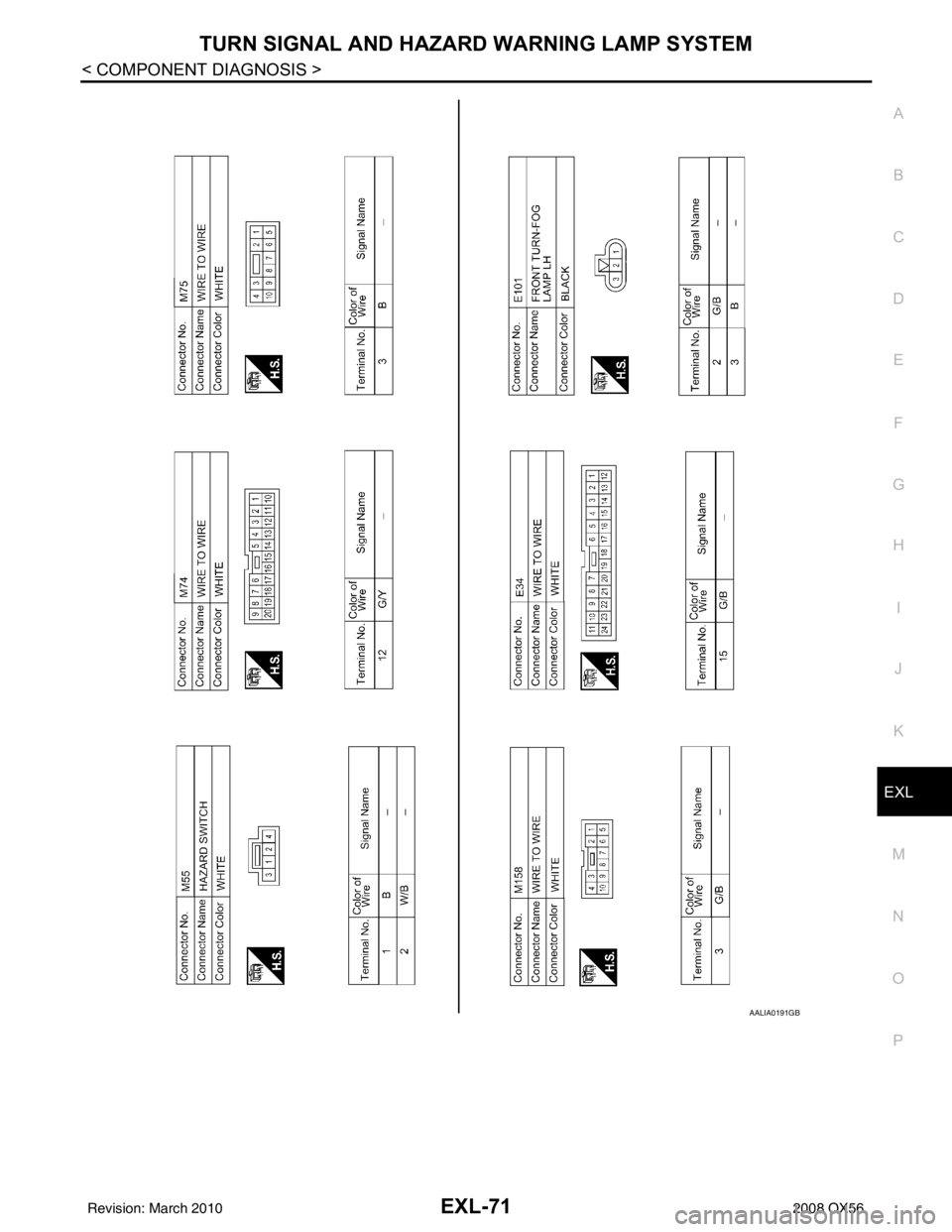
TURN SIGNAL AND HAZARD WARNING LAMP SYSTEM
TURN SIGNAL AND HAZARD WARNING LAMP SYSTEM
Wiring DiagramINFOID:0000000001547147
AALWA0088GB
Revision: March 2010 2008 QX56
Page 1997 of 4083
TURN SIGNAL AND HAZARD WARNING LAMP SYSTEMEXL-69
< COMPONENT DIAGNOSIS >
C
DE
F
G H
I
J
K
M A
B
EXL
N
O P
ALLIA0519GB
Revision: March 2010 2008 QX56
Page 1998 of 4083
EXL-70
< COMPONENT DIAGNOSIS >
TURN SIGNAL AND HAZARD WARNING LAMP SYSTEM
AALIA0190GB
Revision: March 20102008 QX56
Page 1999 of 4083
TURN SIGNAL AND HAZARD WARNING LAMP SYSTEMEXL-71
< COMPONENT DIAGNOSIS >
C
DE
F
G H
I
J
K
M A
B
EXL
N
O P
AALIA0191GB
Revision: March 2010 2008 QX56
Page 2000 of 4083
EXL-72
< COMPONENT DIAGNOSIS >
TURN SIGNAL AND HAZARD WARNING LAMP SYSTEM
AALIA0192GB
Revision: March 20102008 QX56
Page 2001 of 4083
TURN SIGNAL AND HAZARD WARNING LAMP SYSTEMEXL-73
< COMPONENT DIAGNOSIS >
C
DE
F
G H
I
J
K
M A
B
EXL
N
O P
AWLIA0163GB
Revision: March 2010 2008 QX56


