height INFINITI QX56 2008 Factory Workshop Manual
[x] Cancel search | Manufacturer: INFINITI, Model Year: 2008, Model line: QX56, Model: INFINITI QX56 2008Pages: 4083, PDF Size: 81.73 MB
Page 1688 of 4083
![INFINITI QX56 2008 Factory Workshop Manual P2A00, P2A03 A/F SENSOR 1EC-389
< COMPONENT DIAGNOSIS > [VK56DE]
C
D
E
F
G H
I
J
K L
M A
EC
NP
O
10.CHECK INTERMITTENT INCIDENT
Perform GI-35, "
How to Check Terminal" and GI-38, "Intermittent Incide INFINITI QX56 2008 Factory Workshop Manual P2A00, P2A03 A/F SENSOR 1EC-389
< COMPONENT DIAGNOSIS > [VK56DE]
C
D
E
F
G H
I
J
K L
M A
EC
NP
O
10.CHECK INTERMITTENT INCIDENT
Perform GI-35, "
How to Check Terminal" and GI-38, "Intermittent Incide](/img/42/57030/w960_57030-1687.png)
P2A00, P2A03 A/F SENSOR 1EC-389
< COMPONENT DIAGNOSIS > [VK56DE]
C
D
E
F
G H
I
J
K L
M A
EC
NP
O
10.CHECK INTERMITTENT INCIDENT
Perform GI-35, "
How to Check Terminal" and GI-38, "Intermittent Incident".
OK or NG
OK >> GO TO 11.
NG >> Repair or replace.
11 .REPLACE AIR FUEL RATIO (A/F) SENSOR 1
Replace malfunctioning air f uel ratio (A/F) sensor 1.
CAUTION:
• Discard any A/F sensor which has been dropped from a height of more than 0.5 m (19.7 in) onto a
hard surface such as a concrete floor; use a new one.
• Before installing new A/F senso r, clean exhaust system threads using Oxygen Sensor Thread
Cleaner tool J-43897-18 or J-43897-12 and approved anti-seize lubricant.
>> GO TO 12.
12.CONFIRM A/F ADJUSTMENT DATA
1. Turn ignition switch OFF and then ON.
2. Select “A/F ADJ-B1” and “” in “DATA MONITOR” mode with CONSULT-lll.
3. Make sure that “0.000” is displayed on CONSULT-lll screen.
OK or NG
OK >> INSPECTION END
NG >> GO TO 13.
13.CLEAR THE SELF-LEARNING DATA
With CONSULT-lll
1. Start engine and warm it up to normal operating temperature.
2. Select “SELF-LEARNING CONT” in “WORK SUPPORT” mode with CONSULT-lll.
3. Clear the self-learning control coefficient by touching “CLEAR”.
Without CONSULT-lll
1. Start engine and warm it up to normal operating temperature.
2. Turn ignition switch OFF.
3. Disconnect mass air flow sensor harness connector.
4. Restart engine and let it idle for at least 5 seconds.
5. Stop engine and reconnect mass air flow sensor harness con- nector.
6. Make sure DTC P0102 is displayed.
7. Erase the DTC memory. Refer to EC-55, "
Malfunction Indicator
Lamp (MIL)".
8. Make sure DTC P0000 is displayed.
>> GO TO 14.
14.CONFIRM A/F ADJUSTMENT DATA
1. Turn ignition switch OFF and then ON.
2. Select “A/F ADJ-B1” and “A/F ADJ-B2” in “DATA MONITOR” mode with CONSULT-IIl.
3. Make sure that “0.000” is displayed on CONSULT-IIl screen.
>>INSPECTION END
BBIA0368E
Revision: March 2010 2008 QX56
Page 1834 of 4083
EXHAUST MANIFOLD AND THREE WAY CATALYST
EM-31
< ON-VEHICLE REPAIR >
C
D E
F
G H
I
J
K L
M A
EM
NP
O
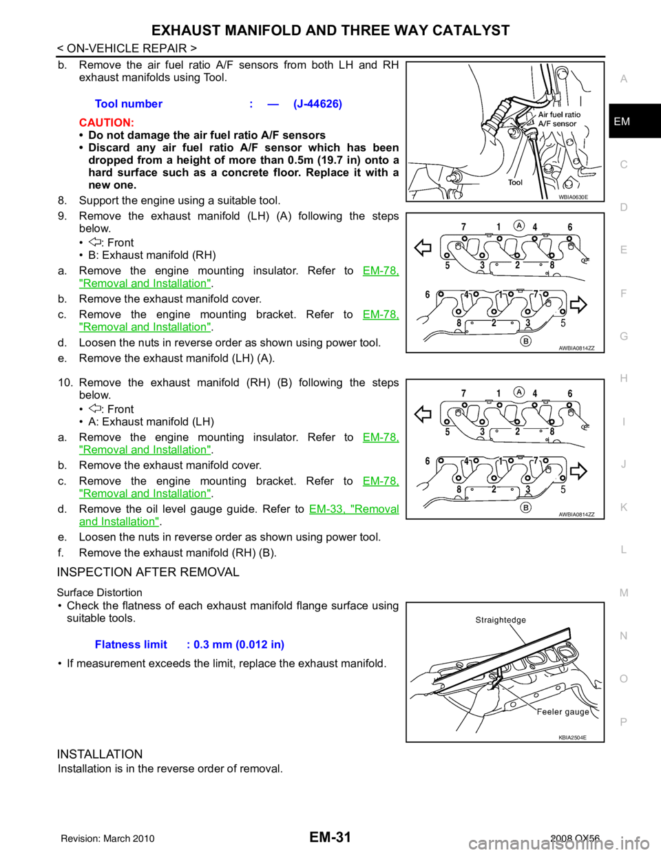
b. Remove the air fuel ratio A/F sensors from both LH and RH
exhaust manifolds using Tool.
CAUTION:
• Do not damage the air fuel ratio A/F sensors
• Discard any air fuel rati o A/F sensor which has been
dropped from a height of more than 0.5m (19.7 in) onto a
hard surface such as a concrete floor. Replace it with a
new one.
8. Support the engine using a suitable tool.
9. Remove the exhaust manifold (LH) (A) following the steps below.
• : Front
• B: Exhaust manifold (RH)
a. Remove the engine mounting insulator. Refer to EM-78,
"Removal and Installation".
b. Remove the exhaust manifold cover.
c. Remove the engine mounting bracket. Refer to EM-78,
"Removal and Installation".
d. Loosen the nuts in reverse order as shown using power tool.
e. Remove the exhaust manifold (LH) (A).
10. Remove the exhaust manifold (RH) (B) following the steps below.
• : Front
• A: Exhaust manifold (LH)
a. Remove the engine mounting insulator. Refer to EM-78,
"Removal and Installation".
b. Remove the exhaust manifold cover.
c. Remove the engine mounting bracket. Refer to EM-78,
"Removal and Installation".
d. Remove the oil level gauge guide. Refer to EM-33, "
Removal
and Installation".
e. Loosen the nuts in reverse order as shown using power tool.
f. Remove the exhaust manifold (RH) (B).
INSPECTION AFTER REMOVAL
Surface Distortion
• Check the flatness of each exhaust manifold flange surface using suitable tools.
• If measurement exceeds the limit, replace the exhaust manifold.
INSTALLATION
Installation is in the reverse order of removal. Tool number
: — (J-44626)
WBIA0630E
AWBIA0814ZZ
AWBIA0814ZZ
Flatness limit : 0.3 mm (0.012 in)
KBIA2504E
Revision: March 2010 2008 QX56
Page 1860 of 4083
CAMSHAFTEM-57
< ON-VEHICLE REPAIR >
C
DE
F
G H
I
J
K L
M A
EM
NP
O
11. Remove the camshaft.
12. Remove the valve lifters if necessary.
• Correctly identify location where each part is removed from. Keep parts organized to avoid mixing them
up.
INSPECTION AFTER REMOVAL
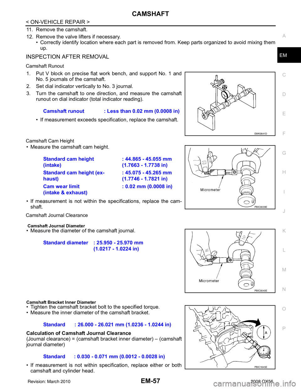
Camshaft Runout
1. Put V block on precise flat work bench, and support No. 1 and No. 5 journals of the camshaft.
2. Set dial indicator vertically to No. 3 journal.
3. Turn the camshaft to one direction, and measure the camshaft runout on dial indicator (total indicator reading).
• If measurement exceeds specif ication, replace the camshaft.
Camshaft Cam Height
• Measure the camshaft cam height.
• If measurement is not within the specifications, replace the cam-
shaft.
Camshaft Journal Clearance
Camshaft Journal Diameter
• Measure the diameter of the camshaft journal.
Camshaft Bracket Inner Diameter
• Tighten the camshaft bracket bolt to the specified torque.
• Measure the inner diameter of the camshaft bracket.
Calculation of Camshaft Journal Clearance
(Journal clearance) = (camshaft bracket inner diameter) – (camshaft
journal diameter)
• If measurement is not within specification, replace either or both
camshaft and cylinder head. Camshaft runout : Less than 0.02 mm (0.0008 in)
EMK0641D
Standard cam height
(intake)
: 44.865 - 45.055 mm
(1.7663 - 1.7738 in)
Standard cam height (ex-
haust) : 45.075 - 45.265 mm
(1.7746 - 1.7821 in)
Cam wear limit
(intake & exhaust) : 0.02 mm (0.0008 in)
PBIC0039E
Standard diameter : 25.950 - 25.970 mm
(1.0217 - 1.0224 in)
PBIC0040E
Standard : 26.000 - 26.021 mm (1.0236 - 1.0244 in)
Standard : 0.030 - 0.071 mm (0.0012 - 0.0028 in)
PBIC1645E
Revision: March 2010 2008 QX56
Page 1867 of 4083
EM-64
< ON-VEHICLE REPAIR >
OIL SEAL
OIL SEAL
Removal and Installation of Valve Oil SealINFOID:0000000001538825
REMOVAL
1. Remove the camshaft relating to the valve oil seal to be removed. Refer to EM-53, "Removal and Installa-
tion".
2. Remove the valve lifters. Refer to EM-53, "
Components".
• Correctly identify the location where each part is removed from. Keep parts organized to avoid mixing
them up.
3. Turn the crankshaft until the cylinder requiring new oil seals is at TDC. This will prevent the valve from
dropping into the cylinder.
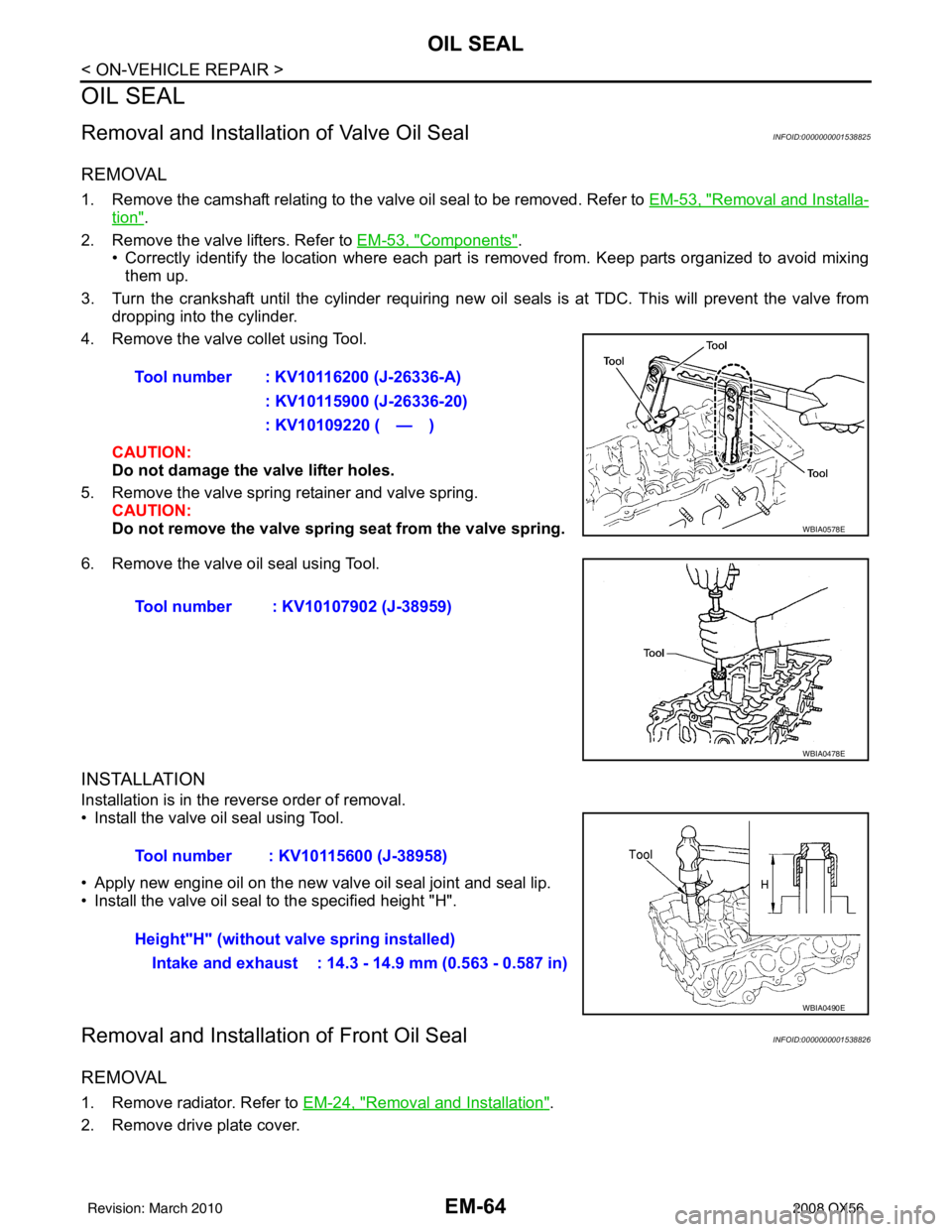
4. Remove the valve collet using Tool.
CAUTION:
Do not damage the valve lifter holes.
5. Remove the valve spring retainer and valve spring. CAUTION:
Do not remove the valve spring seat from the valve spring.
6. Remove the valve oil seal using Tool.
INSTALLATION
Installation is in the reverse order of removal.
• Install the valve oil seal using Tool.
• Apply new engine oil on the new valve oil seal joint and seal lip.
• Install the valve oil seal to the specified height "H".
Removal and Installation of Front Oil SealINFOID:0000000001538826
REMOVAL
1. Remove radiator. Refer to EM-24, "Removal and Installation".
2. Remove drive plate cover. Tool number : KV10116200 (J-26336-A)
: KV10115900 (J-26336-20)
: KV10109220 ( — )
WBIA0578E
Tool number : KV10107902 (J-38959)
WBIA0478E
Tool number : KV10115600 (J-38958)
Height"H" (without valve spring installed)Intake and exhaust : 14.3 - 14.9 mm (0.563 - 0.587 in)
WBIA0490E
Revision: March 2010 2008 QX56
Page 1869 of 4083
EM-66
< ON-VEHICLE REPAIR >
OIL SEAL
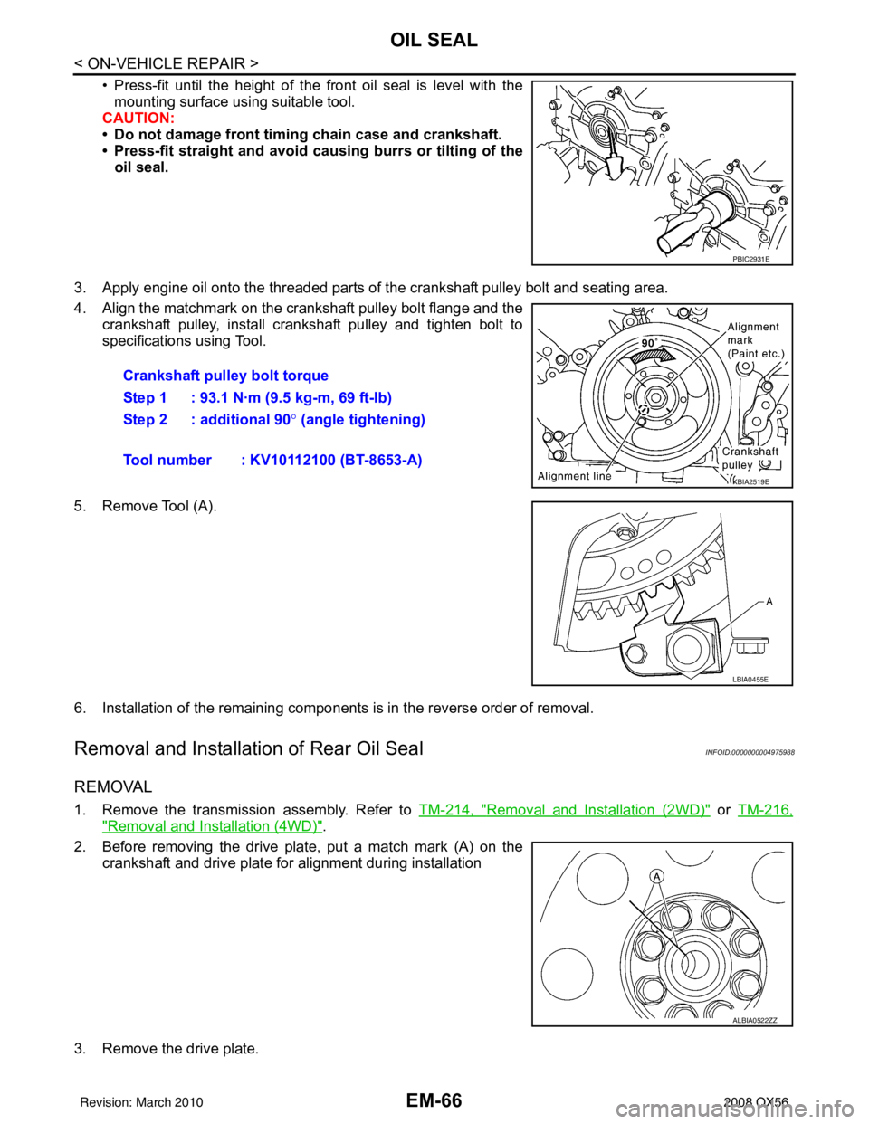
• Press-fit until the height of the front oil seal is level with themounting surface using suitable tool.
CAUTION:
• Do not damage front timing chain case and crankshaft.
• Press-fit straight and avoid cau sing burrs or tilting of the
oil seal.
3. Apply engine oil onto the threaded parts of the crankshaft pulley bolt and seating area.
4. Align the matchmark on the crankshaft pulley bolt flange and the crankshaft pulley, install crankshaft pulley and tighten bolt to
specifications using Tool.
5. Remove Tool (A).
6. Installation of the remaining components is in the reverse order of removal.
Removal and Installation of Rear Oil SealINFOID:0000000004975988
REMOVAL
1. Remove the transmission assembly. Refer to TM-214, "Removal and Installation (2WD)" or TM-216,
"Removal and Installation (4WD)".
2. Before removing the drive plate, put a match mark (A) on the crankshaft and drive plate for alignment during installation
3. Remove the drive plate.
PBIC2931E
Crankshaft pulley bolt torque
Step 1 : 93.1 N·m (9.5 kg-m, 69 ft-lb)
Step 2 : additional 90 ° (angle tightening)
Tool number : KV10112100 (BT-8653-A)
KBIA2519E
LBIA0455E
ALBIA0522ZZ
Revision: March 2010 2008 QX56
Page 1874 of 4083
CYLINDER HEADEM-71
< ON-VEHICLE REPAIR >
C
DE
F
G H
I
J
K L
M A
EM
NP
O
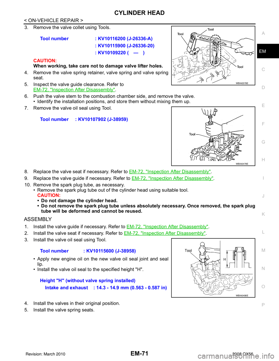
3. Remove the valve collet using Tools.
CAUTION:
When working, take care not to damage valve lifter holes.
4. Remove the valve spring retainer, valve spring and valve spring seat.
5. Inspect the valve guide clearance. Refer to EM-72, "
Inspection After Disassembly".
6. Push the valve stem to the combustion chamber side, and remove the valve. • Identify the installation positions, and store them without mixing them up.
7. Remove the valve oil seal using Tool.
8. Replace the valve seat if necessary. Refer to EM-72, "
Inspection After Disassembly".
9. Replace the valve guide if necessary. Refer to EM-72, "
Inspection After Disassembly".
10. Remove the spark plug tube, as necessary. • Remove the spark plug tube out of the cylinder head using suitable tool.
CAUTION:
• Do not damage the cylinder head.
• Do not remove the spark plug tube unless absolutely necessary. Once removed, the spark plug tube will be deformed and cannot be reused.
ASSEMBLY
1. Install the valve guide if necessary. Refer to EM-72, "Inspection After Disassembly".
2. Install the valve seat if necessary. Refer to EM-72, "
Inspection After Disassembly".
3. Install the valve oil seal using Tool.
• Apply new engine oil on the new valve oil seal joint and seallip.
• Install the valve oil seal to the specified height "H".
4. Install the valves in their original position.
5. Install the valve spring seats. Tool number
: KV10116200 (J-26336-A)
: KV10115900 (J-26336-20)
: KV10109220 ( — )
Tool number : KV10107902 (J-38959)
WBIA0578E
WBIA0478E
Tool number : KV10115600 (J-38958)
Height "H" (without valve spring installed) Intake and exhaust : 14.3 - 14.9 mm (0.563 - 0.587 in)
WBIA0490E
Revision: March 2010 2008 QX56
Page 1875 of 4083
EM-72
< ON-VEHICLE REPAIR >
CYLINDER HEAD
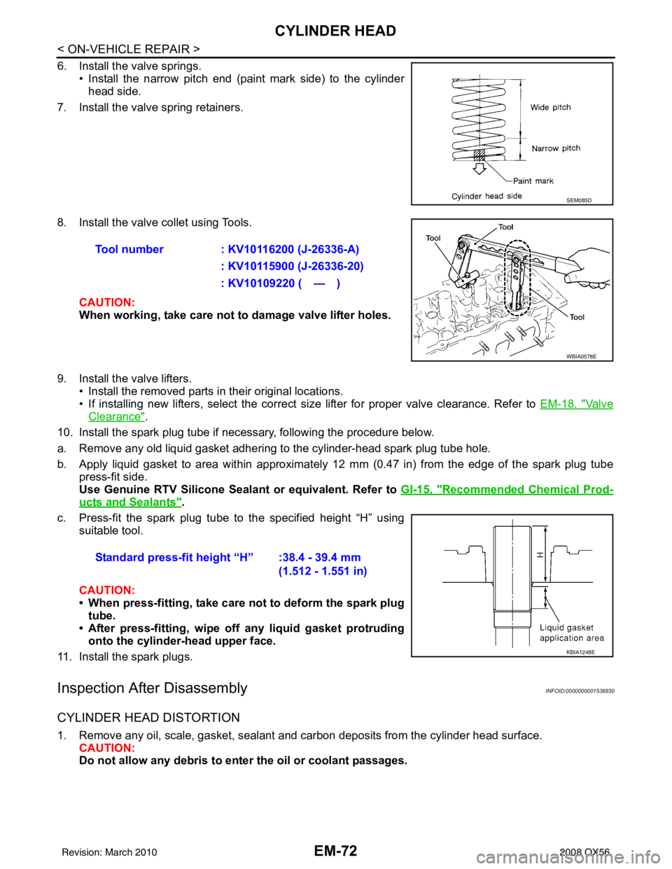
6. Install the valve springs.• Install the narrow pitch end (paint mark side) to the cylinderhead side.
7. Install the valve spring retainers.
8. Install the valve collet using Tools.
CAUTION:
When working, take care not to damage valve lifter holes.
9. Install the valve lifters. • Install the removed parts in their original locations.
• If installing new lifters, select the correct size lifter for proper valve clearance. Refer to EM-18, "
Va l v e
Clearance".
10. Install the spark plug tube if necessary, following the procedure below.
a. Remove any old liquid gasket adhering to the cylinder-head spark plug tube hole.
b. Apply liquid gasket to area within approximately 12 mm (0.47 in) from the edge of the spark plug tube
press-fit side.
Use Genuine RTV Silicone Seal ant or equivalent. Refer to GI-15, "
Recommended Chemical Prod-
ucts and Sealants".
c. Press-fit the spark plug tube to the specified height “H” using suitable tool.
CAUTION:
• When press-fitting, take care not to deform the spark plugtube.
• After press-fitting, wipe off any liquid gasket protruding
onto the cylinder-head upper face.
11. Install the spark plugs.
Inspection After DisassemblyINFOID:0000000001538830
CYLINDER HEAD DISTORTION
1. Remove any oil, scale, gasket, sealant and carbon deposits from the cylinder head surface. CAUTION:
Do not allow any debris to en ter the oil or coolant passages.
SEM085D
Tool number : KV10116200 (J-26336-A)
: KV10115900 (J-26336-20)
: KV10109220 ( — )
WBIA0578E
Standard press-fit height “H” :38.4 - 39.4 mm (1.512 - 1.551 in)
KBIA1248E
Revision: March 2010 2008 QX56
Page 1880 of 4083
CYLINDER HEADEM-77
< ON-VEHICLE REPAIR >
C
DE
F
G H
I
J
K L
M A
EM
NP
O
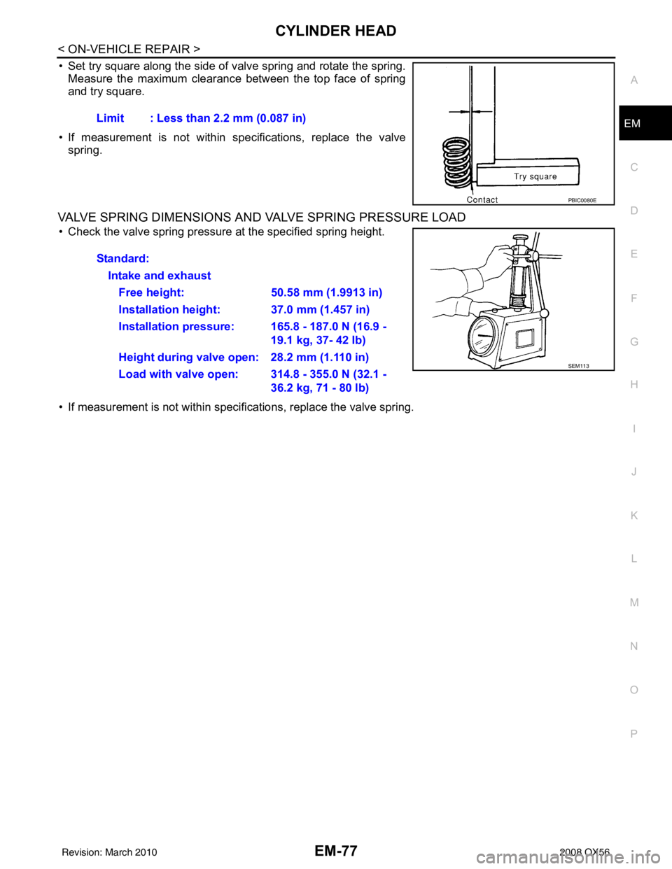
• Set try square along the side of valve spring and rotate the spring.
Measure the maximum clearance between the top face of spring
and try square.
• If measurement is not within specifications, replace the valve spring.
VALVE SPRING DIMENSIONS AND VALVE SPRING PRESSURE LOAD
• Check the valve spring pressure at the specified spring height.
• If measurement is not within specifications, replace the valve spring. Limit : Less than 2.2 mm (0.087 in)
PBIC0080E
Standard:
Intake and exhaustFree height: 50.58 mm (1.9913 in)
Installation height: 37.0 mm (1.457 in)
Installation pressure: 165.8 - 187.0 N (16.9 - 19.1 kg, 37- 42 lb)
Height during valve open: 28.2 mm (1.110 in)
Load with valve open: 314.8 - 355.0 N (32.1 - 36.2 kg, 71 - 80 lb)
SEM113
Revision: March 2010 2008 QX56
Page 1901 of 4083
EM-98
< DISASSEMBLY AND ASSEMBLY >
ENGINE UNIT
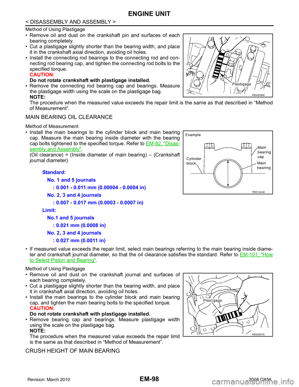
Method of Using Plastigage
• Remove oil and dust on the crankshaft pin and surfaces of eachbearing completely.
• Cut a plastigage slightly shorter than the bearing width, and place
it in the crankshaft axial direction, avoiding oil holes.
• Install the connecting rod beari ngs to the connecting rod and con-
necting rod bearing cap, and tighten the connecting rod bolts to the
specified torque.
CAUTION:
Do not rotate crankshaft with plastigage installed.
• Remove the connecting rod bear ing cap and bearings. Measure
the plastigage width using the scale on the plastigage bag.
NOTE:
The procedure when the measured value exceeds the repair limit is the same as that described in “Method
of Measurement”.
MAIN BEARING OIL CLEARANCE
Method of Measurement
• Install the main bearings to the cylinder block and main bearing cap. Measure the main bearing inside diameter with the bearing
cap bolts tightened to the specified torque. Refer to EM-82, "
Disas-
sembly and Assembly".
(Oil clearance) = (Inside diameter of main bearing) – (Crankshaft
journal diameter)
• If measured value exceeds the repair limit, select main bearings referring to the main bearing inside diame-
ter and crankshaft journal diameter, so that the oil clearance satisfies the standard. Refer to EM-101, "
How
to Select Piston and Bearing".
Method of Using Plastigage
• Remove oil and dust on the crankshaft journal and surfaces of
each bearing completely.
• Cut a plastigage slightly shorter than the bearing width, and place it in crankshaft axial direction, avoiding oil holes.
• Install the main bearings to the cylinder block and main bearing cap, and tighten the main bearing bolts to the specified torque.
CAUTION:
Do not rotate crankshaft with plastigage installed.
• Remove bearing cap and bearings. Measure plastigage width using the scale on the plastigage bag.
NOTE:
The procedure when the measured value exceeds the repair limit
is the same as that descri bed in “Method of Measurement”.
CRUSH HEIGHT OF MAIN BEARING
KBIA2550E
Standard:
No. 1 and 5 journals : 0.001 - 0.011 mm (0.00004 - 0.0004 in)
No. 2, 3 and 4 journals : 0.007 - 0.017 mm (0.0003 - 0.0007 in)
Limit: No.1 and 5 journals : 0.021 mm (0.0008 in)
No. 2, 3 and 4 journals : 0.027 mm (0.0011 in)
PBIC1644E
KBIA2551E
Revision: March 2010 2008 QX56
Page 1902 of 4083
ENGINE UNITEM-99
< DISASSEMBLY AND ASSEMBLY >
C
DE
F
G H
I
J
K L
M A
EM
NP
O
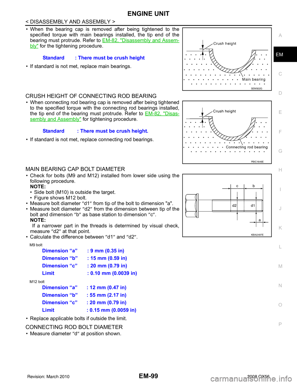
• When the bearing cap is removed after being tightened to the
specified torque with main bearings installed, the tip end of the
bearing must protrude. Refer to EM-82, "
Disassembly and Assem-
bly" for the tightening procedure.
• If standard is not met, replace main bearings.
CRUSH HEIGHT OF CONNECTING ROD BEARING
• When connecting rod bearing cap is removed after being tightened to the specified torque with the connecting rod bearings installed,
the tip end of the bearing must protrude. Refer to EM-82, "
Disas-
sembly and Assembly" for tightening procedure.
• If standard is not met, replace connecting rod bearings.
MAIN BEARING CAP BOLT DIAMETER
• Check for bolts (M9 and M12) installed from lower side using the following procedure.
NOTE:
• Side bolt (M10) is outside the target.
• Figure shows M12 bolt.
• Measure bolt diameter ″ d1″ from tip of the bolt to dimension "a".
• Measure bolt diameter ″d2″ from the dimension between tip of the
bolt and dimension ″b ″ as base station to dimension ″c″ .
NOTE:
If a narrower part in the threads is determined by visual check,
measure ″d2″ at that point.
• Calculate the difference between ″d1″ and ″d2″ .
M9 bolt
M12 bolt
• Replace applicable bolts if outside the limit.
CONNECTING ROD BOLT DIAMETER
• Measure diameter ″d ″ at position shown.
Standard : There must be crush height
SEM502G
Standard : There must be crush height.
PBIC1646E
KBIA2497E
Dimension “a” : 9 mm (0.35 in)
Dimension “b” : 15 mm (0.59 in)
Dimension “c” : 20 mm (0.79 in)
Limit : 0.10 mm (0.0039 in)
Dimension “a” : 12 mm (0.47 in)
Dimension “b” : 55 mm (2.17 in)
Dimension “c” : 20 mm (0.79 in)
Limit : 0.15 mm (0.0059 in)
Revision: March 2010
2008 QX56