battery INFINITI QX56 2008 Factory Service Manual
[x] Cancel search | Manufacturer: INFINITI, Model Year: 2008, Model line: QX56, Model: INFINITI QX56 2008Pages: 4083, PDF Size: 81.73 MB
Page 3759 of 4083
TM-212
< ON-VEHICLE REPAIR >
CONTROL VALVE WITH TCM
After completing installation, check A/T fluid leakage and fluid level. Refer to TM-178, "Checking the A/
T Fluid (ATF)".
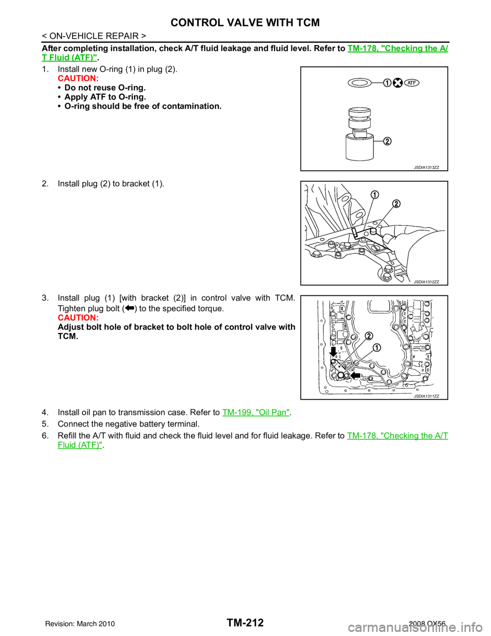
1. Install new O-ring (1) in plug (2). CAUTION:
• Do not reuse O-ring.
• Apply ATF to O-ring.
• O-ring should be free of contamination.
2. Install plug (2) to bracket (1).
3. Install plug (1) [with bracket (2)] in control valve with TCM. Tighten plug bolt ( ) to the specified torque.
CAUTION:
Adjust bolt hole of bracket to bolt hole of control valve with
TCM.
4. Install oil pan to transmission case. Refer to TM-199, "
Oil Pan".
5. Connect the negative battery terminal.
6. Refill the A/T with fluid and check the fluid level and for fluid leakage. Refer to TM-178, "
Checking the A/T
Fluid (ATF)".
JSDIA1313ZZ
JSDIA1312ZZ
JSDIA1311ZZ
Revision: March 2010 2008 QX56
Page 3761 of 4083
TM-214
< REMOVAL AND INSTALLATION >
TRANSMISSION ASSEMBLY
REMOVAL AND INSTALLATION
TRANSMISSION ASSEMBLY
Removal and Installation (2WD)INFOID:0000000004917498
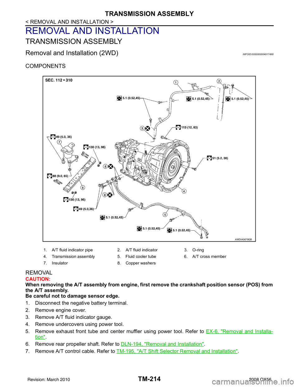
COMPONENTS
REMOVAL
CAUTION:
When removing the A/T assembly from engine, first remove the crankshaft position sensor (POS) from
the A/T assembly.
Be careful not to damage sensor edge.
1. Disconnect the negative battery terminal.
2. Remove engine cover.
3. Remove A/T fluid indicator gauge.
4. Remove undercovers using power tool.
5. Remove exhaust front tube and center muffler using power tool. Refer to EX-6, "
Removal and Installa-
tion".
6. Remove rear propeller shaft. Refer to DLN-194, "
Removal and Installation".
7. Remove A/T control cable. Refer to TM-195, "
A/T Shift Selector Removal and Installation".
1. A/T fluid indicator pipe 2. A/T fluid indicator 3. O-ring
4. Transmission assembly 5. Fluid cooler tube6. A/T cross member
7. Insulator 8. Copper washers
AWDIA0679GB
Revision: March 2010 2008 QX56
Page 3764 of 4083
TRANSMISSION ASSEMBLYTM-217
< REMOVAL AND INSTALLATION >
CEF
G H
I
J
K L
M A
B
TM
N
O P
REMOVAL
CAUTION:
When removing the A/T assembly from engine, firs t remove the crankshaft position sensor (POS) from
the A/T assembly.
Be careful not to damage sensor edge.
1. Disconnect the negative battery terminal.
2. Remove engine cover using power tool.
3. Remove A/T fluid indicator.
4. Remove undercovers using power tool.
5. Remove exhaust front tube and center muffler using power tool. Refer to EX-6, "
Removal and Installa-
tion".
6. Remove propeller shafts. Refer to DLN-194, "
Removal and Installation".
7. Remove A/T control cable. Refer to TM-195, "
A/T Shift Selector Removal and Installation".
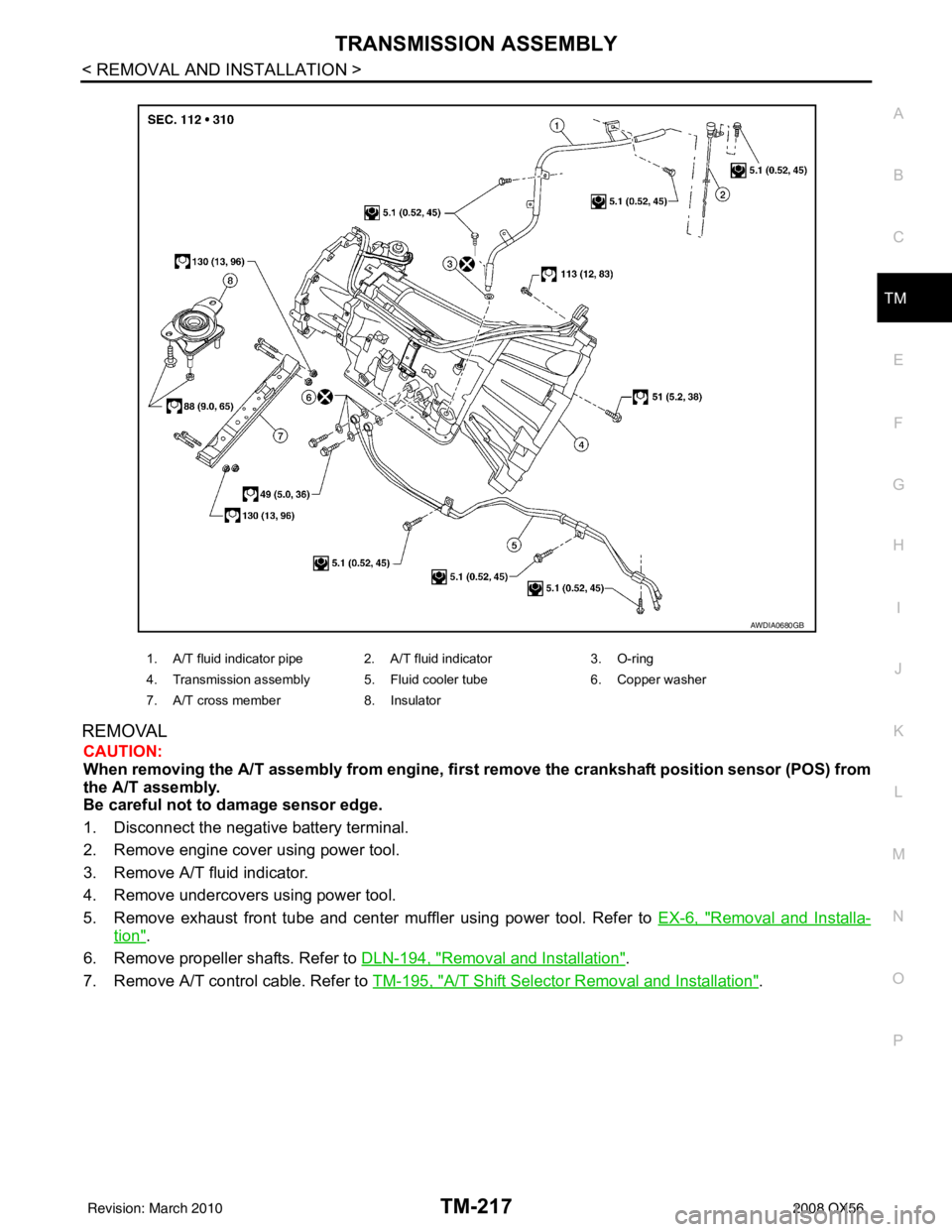
1. A/T fluid indicator pipe 2. A/T fluid indicator 3. O-ring
4. Transmission assembly 5. Fluid cooler tube 6. Copper washer
7. A/T cross member 8. Insulator
AWDIA0680GB
Revision: March 2010 2008 QX56
Page 3841 of 4083

VTL-1
VENTILATION, HEATER & AIR CONDITIONER
C
DE
F
G H
J
K L
M
SECTION VTL
A
B
VTL
N
O P
CONTENTS
VENTILATION SYSTEM
PRECAUTION ....... ........................................2
PRECAUTIONS .............................................. .....2
Precaution for Supplemental Restraint System
(SRS) "AIR BAG" and "SEAT BELT PRE-TEN-
SIONER" ............................................................. ......
2
Precaution Necessary for Steering Wheel Rota-
tion After Battery Disconnect ............................... ......
2
Precaution for Working with HFC-134a (R-134a) ......3
Precaution for Procedure without Cowl Top Cover ......3
PREPARATION ............................................4
PREPARATION .............................................. .....4
Commercial Service Tool .................................... ......4
FUNCTION DIAGNOSIS ...............................5
IN-CABIN MICROFILTER .............................. .....5
Description .......................................................... ......5
ON-VEHICLE MAINTENANCE .....................6
IN-CABIN MICROFILTER .............................. .....6
Removal and Installation ...........................................6
ON-VEHICLE REPAIR .... ..............................7
CONTROL UNIT ..................................................7
Removal and Installation ...........................................7
IN-VEHICLE SENSOR ................................... .....9
Removal and Installation ...........................................9
OPTICAL SENSOR ........................................ ....10
Removal and Installation .........................................10
INTAKE SENSOR ..............................................11
Removal and Installation .........................................11
BLOWER MOTOR .......................................... ....12
Component .......................................................... ....12
Removal and Installation ..................................... ....12
IN-CABIN MICROFILTER .................................14
Removal and Installation .........................................14
HEATER & COOLING UNIT ASSEMBLY ........15
Component ..............................................................15
Removal and Installation .........................................16
HEATER CORE .................................................18
Component ..............................................................18
Removal and Installation .........................................19
DEFROSTER DOOR MOTOR ..........................21
Removal and Installation .........................................21
INTAKE DOOR MOTOR ...................................22
Removal and Installation .........................................22
MODE DOOR MOTOR ......................................23
Components ............................................................23
Removal and Installation .........................................24
AIR MIX DOOR MOTOR ...................................25
Component ..............................................................25
Removal and Installation .........................................26
VARIABLE BLOWER CONTROL .....................28
Components ............................................................28
Removal and Installation .........................................29
DUCTS AND GRILLES .....................................30
Component ..............................................................30
Removal and Installation .........................................33
REFRIGERANT LINES .....................................35
Removal and Installation for Front Evaporator ........35
Removal and Installation for Rear Evaporator .........36
Removal and Installation for Rear Expansion
Valve ........................................................................
37
Revision: March 2010 2008 QX56
Page 3842 of 4083
VTL-2
< PRECAUTION >
PRECAUTIONS
PRECAUTION
PRECAUTIONS
Precaution for Supplemental Restraint System (SRS) "AIR BAG" and "SEAT BELT
PRE-TENSIONER"
INFOID:0000000004884177
The Supplemental Restraint System such as “A IR BAG” and “SEAT BELT PRE-TENSIONER”, used along
with a front seat belt, helps to reduce the risk or severity of injury to the driver and front passenger for certain
types of collision. This system includes seat belt switch inputs and dual stage front air bag modules. The SRS
system uses the seat belt switches to determine the front air bag deployment, and may only deploy one front
air bag, depending on the severity of a collision and w hether the front occupants are belted or unbelted.
Information necessary to service the system safely is included in the SR and SB section of this Service Man-
ual.
WARNING:
• To avoid rendering the SRS inopera tive, which could increase the risk of personal injury or death in
the event of a collision which would result in air bag inflation, all maintenance must be performed by
an authorized NISSAN/INFINITI dealer.
• Improper maintenance, including in correct removal and installation of the SRS, can lead to personal
injury caused by unintent ional activation of the system. For re moval of Spiral Cable and Air Bag
Module, see the SR section.
• Do not use electrical test equipmen t on any circuit related to the SRS unless instructed to in this
Service Manual. SRS wiring harn esses can be identified by yellow and/or orange harnesses or har-
ness connectors.
PRECAUTIONS WHEN USING POWER TOOLS (AIR OR ELECTRIC) AND HAMMERS
WARNING:
• When working near the Airbag Diagnosis Sensor Unit or other Airbag System sensors with the Igni-
tion ON or engine running, DO NOT use air or electri c power tools or strike near the sensor(s) with a
hammer. Heavy vibration could activate the sensor( s) and deploy the air bag(s), possibly causing
serious injury.
• When using air or electric power tools or hammers , always switch the Ignition OFF, disconnect the
battery, and wait at least 3 minu tes before performing any service.
Precaution Necessary for Steering W heel Rotation After Battery Disconnect
INFOID:0000000004884178
NOTE:
• This Procedure is applied only to models with Intelligent Key system and NATS (NISSAN ANTI-THEFT SYS-
TEM).
• Remove and install all control units after disconnecting both battery cables with the ignition knob in the
″LOCK ″ position.
• Always use CONSULT-III to perform self-diagnosis as a part of each function inspection after finishing work.
If DTC is detected, perform trouble diagnosis according to self-diagnostic results.
For models equipped with the Intelligent Key system and NATS, an electrically controlled steering lock mech-
anism is adopted on the key cylinder.
For this reason, if the battery is disconnected or if the battery is discharged, the steering wheel will lock and
steering wheel rotation will become impossible.
If steering wheel rotation is required when battery pow er is interrupted, follow the procedure below before
starting the repair operation.
OPERATION PROCEDURE
1. Connect both battery cables. NOTE:
Supply power using jumper cables if battery is discharged.
2. Use the Intelligent Key or mechanical key to turn the ignition switch to the ″ACC ″ position. At this time, the
steering lock will be released.
3. Disconnect both battery cables. The steering lock will remain released and the steering wheel can be rotated.
4. Perform the necessary repair operation.
Revision: March 2010 2008 QX56
Page 3843 of 4083
PRECAUTIONSVTL-3
< PRECAUTION >
C
DE
F
G H
J
K L
M A
B
VTL
N
O P
5. When the repair work is completed, return the ignition switch to the ″LOCK ″ position before connecting
the battery cables. (At this time, the steering lock mechanism will engage.)
6. Perform a self-diagnosis check of al l control units using CONSULT-III.
Precaution for Working with HFC-134a (R-134a)INFOID:0000000001516598
WARNING:
• CFC-12 (R-12) refrigerant and HFC-134a (R-134a) refr igerant are not compatible. If the refrigerants
are mixed compressor failure is likely to occur. Refer to HA-4, "
Contaminated Refrigerant". To deter-
mine the purity of HFC-134a (R-134a) in the vehicle and recovery tank, use recovery/recycling equip-
ment and refrigerant identifier.
• Use only specified oil for the HFC-134a (R-134a) A/C system and HFC-134a (R-134a) components. If
oil other than that specified is used, compressor fa ilure is likely to occur.
• The specified HFC-134a (R-134a) oil rapidly absorb s moisture from the atmosphere. The following
handling precautions must be observed:
- When removing refrigerant components from a vehicle, immediately cap (seal) the component to
minimize the entry of mois ture from the atmosphere.
- When installing refrigerant components to a vehicle, do not remove the caps (unseal) until just
before connecting the co mponents. Connect all refrigerant lo op components as quickly as possible
to minimize the entry of moisture into system.
- Only use the specified oil from a sealed container. Immediately r eseal containers of oil. Without
proper sealing, oil will become moisture saturat ed and should not be used.
- Avoid breathing A/C refrigerant and oil vapor or mist. Exposure may irritate eyes, nose and throat.
Remove HFC-134a (R-134a) from the A/C system usi ng certified service equipment meeting require-
ments of SAE J2210 [HFC-134a (R-134a) recycling eq uipment], or J2209 [HFC-134a (R-134a) recovery
equipment]. If accidental system discharge occurs , ventilate work area before resuming service.
Additional health and safety information may be ob tained from refrigerant and oil manufacturers.
- Do not allow A/C oil to come in contact with styrofoam parts. Damage may result.
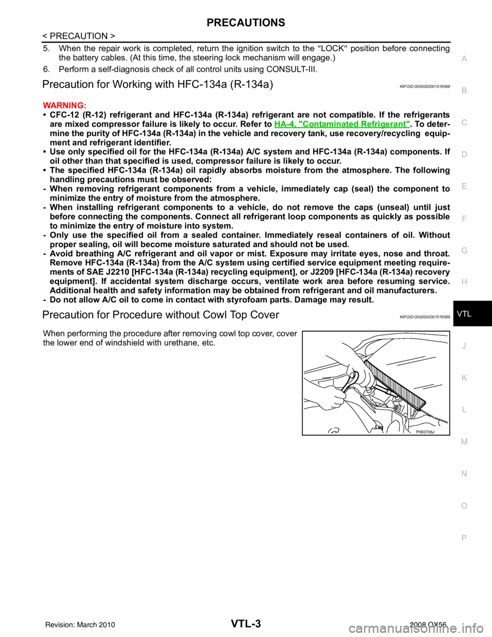
Precaution for Procedur e without Cowl Top CoverINFOID:0000000001516599
When performing the procedure after removing cowl top cover, cover
the lower end of windshield with urethane, etc.
PIIB3706J
Revision: March 2010 2008 QX56
Page 3857 of 4083
HEATER & COOLING UNIT ASSEMBLYVTL-17
< ON-VEHICLE REPAIR >
C
DE
F
G H
J
K L
M A
B
VTL
N
O P
1. Move the two front seats to the rear most position on the seat track.
2. Disconnect the battery negative terminal and battery positive terminal.
3. Discharge the refrigerant from the A/C system. Refer to HA-20, "
HFC-134a (R-134a) Service Procedure".
4. Drain the coolant from the engine cooling system. Refer to CO-11, "
Changing Engine Coolant".
5. Disconnect the front heater hoses from the front heater core.
6. Disconnect the high/low pressure pipes from the front expansion valve.
7. Remove the instrument panel and console panel. Refer to IP-12, "
Removal and Installation".
8. Remove the steering column. Refer to ST-20, "
Removal and Installation".
9. Disconnect the instrument panel wire harness at t he RH and LH in-line connector brackets, and the fuse
block (J/B) electrical connectors. Refer to PG-9, "
Wiring Diagram — Battery Power Supply —".
10. Disconnect the steering member from each side of the vehicle body.
11. Remove the front heater and cooling unit assembly with it attached to the steering member, from the vehi- cle.
CAUTION:
Use care not to damage the seats and interior trim panels when removing the front heater and
cooling unit assembly with it at tached to the steering member.
12. Remove the front heater and cooling uni t assembly from the steering member.
Installation
Installation is in the reverse order of removal.
CAUTION:
• Replace the O-ring of the low-pressure pipe and high-pressure pipe with a new one, and apply com-
pressor oil to it when installing it.
• After charging the refrigerant, check for leaks.
NOTE:
• Fill the engine cooling system with the specified coolant mixture. Refer to CO-11, "
Changing Engine Cool-
ant".
• Recharge the A/C system. Refer to HA-20, "
HFC-134a (R-134a) Service Procedure".
REAR HEATER AND COOLING UNIT ASSEMBLY
Removal
1. Discharge the refrigerant from the A/C system. Refer to HA-20, "HFC-134a (R-134a) Service Procedure".
2. Drain the coolant from the engine cooling system. Refer to CO-11, "
Changing Engine Coolant".
3. Remove the luggage side finisher lower RH. Refer to INT-19, "
Removal and Installation".
4. Disconnect the rear heater core hoses from the rear heater core.
5. Disconnect the rear A/C pipes from the rear expansion valve.
6. Disconnect the following electrical connectors: • Rear blower motor
• Rear variable blower control
• Rear air mix door motor
7. Disconnect the ducts from the rear heater and cooling unit assembly.
8. Remove the rear heater and cooling unit assembly.
Installation
Installation is in the reverse order of removal.
CAUTION:
• Replace the O-ring of the low-pressure pipe and high-pressure pipe with a new one, and apply com- pressor oil to it when installing it.
• After charging the refrigerant, check for leaks.
NOTE:
• Fill the engine cooling system with the specified coolant mixture. Refer to CO-11, "
Changing Engine Cool-
ant".
• Recharge the A/C system. Refer to HA-20, "
HFC-134a (R-134a) Service Procedure".
Revision: March 2010 2008 QX56
Page 3879 of 4083

WCS-2
WARNING CHIME SYSTEM .............................24
Wiring Diagram .................................................... ...24
ECU DIAGNOSIS ..................................... ...29
COMBINATION METER ................................. ...29
Reference Value .................................................. ...29
Wiring Diagram .......................................................31
Fail Safe .................................................................48
DTC Index ..............................................................49
BCM (BODY CONTROL MODULE) ..................51
Reference Value .................................................. ...51
Terminal Layout ......................................................53
Physical Values ......................................................53
Wiring Diagram .......................................................59
Fail Safe .................................................................62
DTC Inspection Priority Chart ..............................63
DTC Index ........................................................... ...63
SYMPTOM DIAGNOSIS .............................65
THE LIGHT REMINDER WARNING DOES
NOT SOUND ................................................... ...
65
Description ........................................................... ...65
Diagnosis Procedure ...............................................65
THE SEAT BELT WARNING CONTINUES
SOUNDING, OR DOES NOT SOUND ...............
66
Description ........................................................... ...66
Diagnosis Procedure ...............................................66
THE KEY WARNING DOES NOT SOUND .......67
Description ........................................................... ...67
Diagnosis Procedure ...............................................67
PRECAUTION ............................................68
PRECAUTIONS .............................................. ...68
Precaution for Supplemental Restraint System
(SRS) "AIR BAG" and "SEAT BELT PRE-TEN-
SIONER" .............................................................. ...
68
Precaution Necessary for Steering Wheel Rota-
tion After Battery Disconnect ..................................
68
Revision: March 2010 2008 QX56
Page 3889 of 4083
WCS-12
< FUNCTION DIAGNOSIS >
DIAGNOSIS SYSTEM (METER)
DIAGNOSIS SYSTEM (METER)
Diagnosis DescriptionINFOID:0000000004872660
SELF-DIAGNOSIS MODE
The following items can be checked during Combination Meter Self-Diagnosis Mode.
• Gauge sweep and present gauge values.
• Illuminates all odometer/trip meters and A/T indicator segments.
• Illuminates all micro controlled lamps/LEDs regardless of switch position.
• Displays estimated present battery voltage.
• Displays seat belt buckle switch LH status.
OPERATION PROCEDURE
NOTE:
• Once entered, combination meter self-diagnosis mode will function with the ignition switch in ON or START.
Combination meter self-diagnosis mode will exit upon turning the ignition switch to OFF or ACC.
• If the diagnosis function is activated with trip A displa yed, the mileage on trip A is reset to 0000.0. (Trip B
operates the same way.)
To initiate combination meter self-diagnosis mode, refer to the following procedure.
1. Turn the ignition switch ON, while pressing the odometer/trip meter switch for 5 - 8 \
seconds. When the diagnosis function is activated, the odometer/trip meter will display tESt.
NOTE:
Check combination meter power supply and ground circuit when self-diagnosis mode of combination meter
does not start. Refer to MWI-30, "
COMBINATION METER : Diagnosis Procedure". Replace combination
meter if normal. Refer to MWI-76, "
Removal and Installation".
COMBINATION METER SELF-DIAGNOSIS MODE FUNCTIONS
To interpret combination meter self-diagnosis mode functions, refer to the following table.
EventOdometer Display Description of Test/Data Notes:
Odometer/trip meter A/B
switch held from 5 to 8
seconds (or until re-
leased) tESt
Initiating self-diagnosis mode
Switch released GAGE Performs sweep of all
gauges, then displays
present gauge values.Gauges sweep within 10 seconds
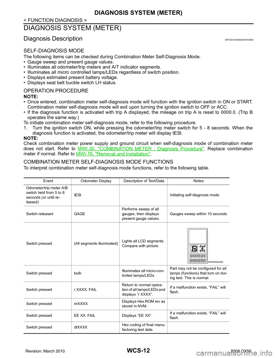
Switch pressed (All segments illuminated) Lights all LCD segments.
Compare with picture.
Switch pressed bulbIlluminates all micro-con-
trolled lamps/LEDs. Part may not be configured for all
lamps (functions) th
at turn on dur-
ing test. This is normal.
Switch pressed r XXXX, FAIL Return to normal opera-
tion of all lamps/LEDs and
displays “r XXXX”.If a malfunction exists, “FAIL” will
flash.
Switch pressed nrXXXX Displays Hex ROM rev as
stored in NVM.
Switch pressed EE XX, FAIL Displays “EE XX”.If a malfunction exists, “FAIL” will
flash.
Switch pressed dtXXXX Hex coding of final manu-
facturing test date.
AWNIA0203ZZ
Revision: March 2010
2008 QX56
Page 3890 of 4083
WCS
DIAGNOSIS SYSTEM (METER)WCS-13
< FUNCTION DIAGNOSIS >
C
DE
F
G H
I
J
K L
M B A
O P
CONSULT-III Function (METER/M&A)INFOID:0000000004872661
CONSULT-III can display each diagnostic item us ing the diagnostic test modes shown following.
SELF-DIAG RESULTS
Display Item List
Refer to MWI-62, "DTC Index".
DATA MONITOR
Display Item List
Switch pressed
(3 times) Sc1 XX through Epr XXDisplays 8 bit software
configuration value in Hex
format
Switch pressed 1nF XXDisplays 8-bit market info
value in Hex format. $31 = USA
$2A = Canada
Switch pressed
(3 times) cYL XX through tF N/A
Switch pressed XXXXX “Corrected” speed value
in hundredths of MPH.
Gauge indication may be
slightly higher. This is nor-
mal.Will display “-----” if message is not
received. Will display “99999” if
data received is invalid.
Switch pressed XXXXX “Corrected” speed value
in hundredths of KPH.
Gauge indication may be
slightly different. This is
normal.Will display “-----” if message is not
received. Will display “99999” if
data received is invalid.
Switch pressed t XXXX Tachometer value in
RPM. Gauge indication
may be higher at higher
RPM. This is normal.Will display “-----” if message is not
received.
Switch pressed F1XXXX Present fuel level A/D in-
put. This input represents
fuel sender input.000-009 = Short circuit
010-254 = Normal range
255 = Open circuit
Switch pressed F2XXX Present FLPS.010-254 = Normal range
Switch pressed XXXC Last temperature gauge
input value in degrees C.
Temperature gauge indi-
cates present tempera-
ture per indication
standard.Will display “---”C if
message is not
received.
Will display “999” if data received
is invalid.
High = 130 deg C
Normal = 70 - 105 deg C
Low = less than 50 deg C
Switch pressed BAtXX.X Estimated present battery
voltage.
Switch pressed rES -X Seat belt buckle switch LH
status.1= Buckled
0 = Unbuckled
Switch pressed
(32 times) PA -XX through PA1-XX N/A
Switch pressed GAGE Return to beginning of self-diagno-
sis cycle.
Event
Odometer Display Description of Test/Data Notes:
METER/M&A diagnosis mode Description
SELF-DIAG RESULTS Displays combination meter self-diagnosis results. DATA MONITOR Displays combination meter input/output data in real time.
CAN DIAG SUPPORT MNTR The result of transmit/receive diagnosis of CAN communication can be read.
Revision: March 2010 2008 QX56